EP0820068A1 - Ensemble d'un couvercle et de ses équipements associés - Google Patents
Ensemble d'un couvercle et de ses équipements associés Download PDFInfo
- Publication number
- EP0820068A1 EP0820068A1 EP97304999A EP97304999A EP0820068A1 EP 0820068 A1 EP0820068 A1 EP 0820068A1 EP 97304999 A EP97304999 A EP 97304999A EP 97304999 A EP97304999 A EP 97304999A EP 0820068 A1 EP0820068 A1 EP 0820068A1
- Authority
- EP
- European Patent Office
- Prior art keywords
- shroud
- air
- air flow
- seismic support
- crdm
- Prior art date
- Legal status (The legal status is an assumption and is not a legal conclusion. Google has not performed a legal analysis and makes no representation as to the accuracy of the status listed.)
- Granted
Links
Images

Classifications
-
- G—PHYSICS
- G21—NUCLEAR PHYSICS; NUCLEAR ENGINEERING
- G21C—NUCLEAR REACTORS
- G21C13/00—Pressure vessels; Containment vessels; Containment in general
- G21C13/02—Details
- G21C13/06—Sealing-plugs
- G21C13/073—Closures for reactor-vessels, e.g. rotatable
-
- G—PHYSICS
- G21—NUCLEAR PHYSICS; NUCLEAR ENGINEERING
- G21C—NUCLEAR REACTORS
- G21C7/00—Control of nuclear reaction
- G21C7/06—Control of nuclear reaction by application of neutron-absorbing material, i.e. material with absorption cross-section very much in excess of reflection cross-section
- G21C7/08—Control of nuclear reaction by application of neutron-absorbing material, i.e. material with absorption cross-section very much in excess of reflection cross-section by displacement of solid control elements, e.g. control rods
- G21C7/12—Means for moving control elements to desired position
-
- Y—GENERAL TAGGING OF NEW TECHNOLOGICAL DEVELOPMENTS; GENERAL TAGGING OF CROSS-SECTIONAL TECHNOLOGIES SPANNING OVER SEVERAL SECTIONS OF THE IPC; TECHNICAL SUBJECTS COVERED BY FORMER USPC CROSS-REFERENCE ART COLLECTIONS [XRACs] AND DIGESTS
- Y02—TECHNOLOGIES OR APPLICATIONS FOR MITIGATION OR ADAPTATION AGAINST CLIMATE CHANGE
- Y02E—REDUCTION OF GREENHOUSE GAS [GHG] EMISSIONS, RELATED TO ENERGY GENERATION, TRANSMISSION OR DISTRIBUTION
- Y02E30/00—Energy generation of nuclear origin
- Y02E30/30—Nuclear fission reactors
Definitions
- the invention relates to a head assembly for a nuclear reactor pressure vessel and more particularly to a simplified integrated head assembly.
- CRDMs control rod drive mechanism assemblies
- the CRDMs are mechanically supported on a removable closure head bolted to the pressure vessel and laterally supported by a seismic support platform and vertically restrained by a missile shield.
- the closure head must also mechanically support a complex ventilation system located above the closure head for providing a substantial, continuous flow of ambient containment air through the CRDM coil region. See, in this regard, Figure 1 of US Patent No. 4,678,623 which shows a head arrangement found in many commercial facilities.
- Figure 1 shows a design wherein the surrounding ambient air below the seismic support platform 28 is drawn across the unbaffled upper portion of the CRDMs, downwardly along the baffled electromagnetic coils of the CRDMs, into a lower plenum 20, upwardly through ducts 22 into an upper plenum 24 and then exhausted by fans 26 into the surrounding atmosphere above the fans.
- the hot exhaust air from the CRDMs can be blown into the general containment atmosphere so that the walls of the refueling canal near the head of the reactor vessel are not be substantially heated. Concrete walls should not be exposed to temperatures of about 150°F and are preferably not exposed to temperatures of more than 120°F.
- a closure head may also support a shield surrounding the CRDM assemblies for protecting maintenance workers from radioactive CRDM assemblies.
- the closure head, CRDM assemblies and their supporting subsystems and other devices located over the closure head must be disassembled, lifted and removed so that the closure head can be removed and the spent fuel assemblies in the core of the pressure vessel below can be rearranged or replaced with fresh fuel assemblies.
- an integrated head assembly was developed in the 1980s as a backfit for the design discussed above. As is shown in Figure 2 of US Patent No. 4,678,623, the integrated head assembly replaced the ducts 22 extending from the lower plenum to the upper plenum with a duct arrangement 136, 138 and 140 which partially encircled the CRDMs.
- This natural circulation design included a redesigned, taller cooling shroud to increase the natural draft and other features for reducing the air flow resistance through the head region.
- a finite element analysis of the natural circulation design indicated that natural convection could achieve only about one-fourth of the 48,000 cubic feet per minute (CFM) air flow required by the design. Calculations showed that such an arrangement could result in a peak coil surface temperatures of up to about 380°F based upon a continuous stepping heat load estimate of 12 kw/CRDM. Although such conditions may be considered acceptable based on the peak specified allowable temperature of 392°F at the coils, this design provides an assured temperature margin of only 32°F, which might require more frequent replacement of the coils after many years of operation at the increased temperatures.
- the present invention resides in an integrated head assembly which includes a pressure vessel closure head.
- a CRDM seismic support having air flow holes is disposed above the closure head with CRDMs extending upwardly from the closure head through the CRDM seismic support and between the air flow holes of the CRDM seismic support.
- a shroud enclosing the CRDMs extends upwardly from the closure head to the seismic support and is in air flow communication with the seismic support air flow holes.
- the shroud also has an air port, and preferrably more than one air port, in direct air flow communication with the surrounding atmosphere.
- At least one ventilation fan (and preferably three or four fans) is disposed above the closure head and in air flow communication with the air flow passageway defined by the closure head, shroud and seismic support for circulating the air between the ambient atmosphere and the air flow passageway in order to cool the CRDMs in the head assembly.
- large quantities of cooling air ventilate the head assembly to cool the CRDMs without unnecessarily wasting most of the fan power in air ducts during power operation.
- the entire head assembly can be lifted as a unit and transferred during refueling operations. Also, it has been estimated that this head assembly with its CRDM-encircling shroud can be installed in about one third the time required to install the head assembly shown in Figure 2 of US Patent No.
- the integrated head assembly can be employed in new construction or readily backfitted in existing commercial facilities, including those facilities having integrated head assemblies from the 1980s, and may be used with existing lift devices.
- the integrated head assembly includes a downdraft ventilating fan supported on a missile shield superadjacent the CRDM seismic support for blowing atmospheric air downwardly over the CRDMs and then out through one or more air ports into the ambient atmosphere around the head assembly in a refueling canal.
- a downdraft ventilating fan supported on a missile shield superadjacent the CRDM seismic support for blowing atmospheric air downwardly over the CRDMs and then out through one or more air ports into the ambient atmosphere around the head assembly in a refueling canal.
- natural air circulation in the refueling canals of commercial facilities will circulate the air from the head assembly (at a temperature which could be up to about 160°F) upwardly out of the refueling canals.
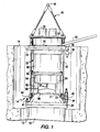
- Figure 1 shows a pressure vessel 10 in a reactor cavity 12 with an integrated head assembly 14 embodying the present invention extending upwardly in one end of a refueling canal 16.
- the head assembly 14 embodying the present invention may be employed in new construction or backfitted to replace any of the various head assemblies shown in the above identified patents.
- the previously mentioned US Patent No. 4,678,623 is hereby incorporated by this reference for its disclosure of the structure of reactor vessels and integrated head assemblies and their component parts.
- Figure 1 generally shows a head assembly 14 as it would appear during power operation.
- the preferred integrated head assembly 14 of Figure 1 generally includes a reactor vessel closure head 20, a plurality of CRDMs 22 (illustrated by one CRDM), a seismic support 24 to laterally support the CRDMs, a missile shield 26 for vertically restraining the CRDMs, one or more fan plena 28 and two or more ventilation fans 30 (either with one large plenum 28 distributing air from each fan 30 as is shown in Figure 1 or with a smaller plenum 28 associated with each fan 30) and a shroud 32 surrounding the CRDMs.
- the shroud 32 extends from the closure head 20 to the seismic support 24.
- the shroud 32 may be supported by the closure head 20 via a support ring 33 or other suitable means.
- the fans 30 may include a spare in a commercial facility, in which case the fans 30 will have backdraft dampers.
- a missile shield may not be employed or may not be integrated into the design of the head assembly.
- a block type missile shield supported by a beam as shown in the above-mentioned US Patent 4,678,623 may be employed in place of an integral missile shield 26.
- the closure head 20 is attached to the reactor vessel 10, covered with head insulation 21.
- the seismic support 24 may have a circumferential track 36 supporting a movable hoist 38 for supporting a stud tensioner 40.
- the stud tensioner tensions and detensions the bolts 41 which seal the closure head 20 against the pressure vessel 10 during power operations at pressures of up to 2250 psi or more and temperatures of up to 650°F or more.
- the seismic support 24 and the missile shield 26 are supported by lift rods 42 bolted to mounting brackets 44 on the closure head 20.
- the lift rods 42 are an integral part of a lift rig 46.
- the lift rig 46 also has a lift eye 48 which may be engaged by an overhead crane (not shown) for removing and replacing the integrated head assembly 14 as a unit.
- a cable tray or bridge 50 may be attached to the missile shield 26 as shown in Figure 1 for supporting CRDM cables, control rod position indicator cables, thermocouple lines and electrical lines. These cables and lines may be connected to the plant systems at a panel on the containment wall above the operating deck or at the pressure vessel. In situations where the available clearances may be too small, the cable tray 50 may be pivotally attached to the missile shield 26 or elsewhere to facilitate the transfer of the closure head 14 during refueling operations.
- FIG 2 is a schematic cross-section of the head assembly 14 which shows a representative CRDM 22 as including a drive rod 52 and electromagnetic coils 54, a RPI coil 56 and an air flow baffle 58 which surrounds the electromagnetic coils 54 of all of the CRDMs 22.
- the CRDMs are raised to a position adjacent the underside of the missile shield 26 as shown in Figure 2.
- the missile shield 26 has a plurality of holes 60 and relatively larger holes 62.
- the smaller holes 60 provide a passageway for the CRDM cables 61 from the below CRDMs 22 and cables 63 from the below RPI coils 56 to the cable tray 50 via the plenum 28 above.
- holes 60 there may be up to 150 to 160 or more holes 60.
- These holes 60 also provide a passageway for ventilating air to pass.
- the larger holes 62 provide additional passage-ways for the flow of ventilating air.
- the total area of the small and large holes is sufficient to provide an air flow velocity of less than about 30 feet/second, and more preferably less than about 20 feet/second, in order to reduce the pressure drop of the flowing air through the head assembly 14.
- a repeating hole pattern like that shown in Figures 2 and 3 or similar patterns would be employed in a commercial facility for providing sufficient cable and air flow passageways.
- the missile shield 26 is preferably superjacent to the seismic support 24 as shown in Figures 1 and 2 in order to reduce the momentum which a failed CRDM 22 might achieve.
- the seismic support 24 includes interlocking aperatured RPI spacer plates 70 peripherally supported by a circumferential support ring 72 via several extendable nut assemblies 74.
- the interlocking spacer plates 70 are arranged so as to define passageways through which the CRDMs 22 and their cables 61 and the RPI coils 56 and their cables 63 extend.
- the RPRs 56 may have flanges 76 which may be laterally supported by the interlocking spacer plates 70.
- the aperatured interlocking plates 70 have large air flow passageways 84.
- the plate as shown in Figure 4 may be fabricated of welded frame members 86 of up to about one foot along each side or more which is supported by cross members 88.
- the total area of the passageways 84 is sufficient to provide an air flow velocity through the support 24 of less than about 30 feet/second, and more preferably of less than about 20 feet/second, for reducing the pressure drop of the air as it flows through the seismic support 24.
- the shroud 32 shown in Figures 1 and 2 generally includes an upper portion 90 flanged to a lower portion 92 which may be fastened together by bolts 93.
- each portion 90 or 92 may be fabricated of from one up to three or more sections.
- each portion 90 or 92 could be fabricated of three 120° arcuate sections which are welded or otherwise suitably jointed together.
- the upper portion 90 is preferably about 0.75 inches thick.
- the lower portion 92 is preferably from about 0.75 inches to about 1.5 inches thick to provide integral gamma personnel shielding.
- the shroud 32 may have access doors 94 for inspecting thermocouple columns (not shown).
- the shroud 32 shown in Figures 1 and 2 has one or more air ports 96 which may be covered with doors 98 which are normally open during power operations for exhausting the flowing air and may be closed during maintenance operations to protect maintenance personnel from radiation due to crud on the CRDMs.
- the air ports 96 are preferably located below the CRDM electromagnetic coils 54 and the baffles 58 which enclose them within the shroud.
- the air ports 96 may have a rectangular or other regular or irregular cross-section. Also, the air ports 96 may have different sizes.
- air ports 96 facing the closely adjacent walls of the refueling canal may have six inches or wider openings and other air ports facing toward the more distant walls of the refueling canal may have twenty four inches or wider openings to control the relative flow of air
- the total cross-section of the air ports 96 is sufficient to maintain the flow of cooling air at a velocity of less than about 30 feet/second, and sore preferably, less than about 10 feet/second in order to reduce the pressure drop and to prevent the exhausted air from flowing across the refueling canal 16 and heating the walls of the canal.
- ambient air from the atmosphere of the containment above the fans 30 is blown downwardly long the entire length of the RPI coils 78 (of about twelve feet) shown in Figure 2 and the baffled CRDM electromagnetic coils 54 and then out through the air ports 96 into the refueling canal 16.
- this air cools electrical cables and connectors as well.
- the air flows out of the shroud 32 at a temperature of less than about 160°F, and more preferably less than about 150°F, in order to cool the head assembly 14 without excessively heating the walls of the refueling canal 16.
- Baffling (not shown) may be mounted to the reactor stud insulation to direct air flow into the refueling canal.
- the doors 98 of the shroud 32 and the baffling mounted on the reactor stud insulation may be adjusted to allow as-installed flow tuning to assure that the correct flow profile is achieved.
- these adjustments also eliminate the need for costly pre-installation flow testing.
- thermal-hydraulic finite element code was used to model the closure head 20, refueling canal 16 and containment.
- the code employed an axisymmetric modeling approximation with correct fan inlet air velocities and an equivalent inlet area for the axisymmetric model.
- finite element code was run on a design having very tight baffling which essentially pushed the heated air from the air ports 96 straight up.
- the thermal plume appeared to be compact enough that the wall temperature would remain about 120°F.
- the air ports 96 will be baffled to direct the exhaust air away from the close sidewalls and into the wide sides of the canal over two arcs of about 80°.
- the head assembly 14 of Figure 1 may be readily backfit to replace an arrangement such as that shown in Figure 1 of US Patent No. 4,678,623.
- the large missile shield and cooling fans shown in this patent at Figure 1 can be eliminated and replace with more efficient devices.
- Existing lifting rigs may be retained without needing in-plant testing if the total weight be lifted does not increase. No electrical cabling need be changed and routine disconnecting over the head may be eliminated if desired. Also, access for inspection of the head insulation and the head penetration area is improved.
- the fans 30 may be employed to draw air into the shroud 32 via the air ports 96 and then discharge the air above the head package 14. Like the first described embodiment, this design will require significantly less power than do the previously described designs.
- An additional advantage of this embodiment is that the relatively hot air is exhausted away from the refueling canal 16 and will not recirculate from the refueling canal. It is noted that auxiliary baffles may be installed on the shroud 32, seismic support 24 or missile shield 26 of the first described embodiment if recirculation is a concern.
- the fans 30 may be located in the air ports 96 and the air circulated between the holes 60 and 62 of the missile shield 26 and the ambient atmosphere.
- the clearances are very tight and specially designed fans may be needed.
Landscapes
- Physics & Mathematics (AREA)
- Engineering & Computer Science (AREA)
- Plasma & Fusion (AREA)
- General Engineering & Computer Science (AREA)
- High Energy & Nuclear Physics (AREA)
- Chemical & Material Sciences (AREA)
- Chemical Kinetics & Catalysis (AREA)
- Monitoring And Testing Of Nuclear Reactors (AREA)
- Fluid-Damping Devices (AREA)
- Vibration Prevention Devices (AREA)
Applications Claiming Priority (2)
| Application Number | Priority Date | Filing Date | Title |
|---|---|---|---|
| US687012 | 1976-05-17 | ||
| US08/687,012 US5742652A (en) | 1996-07-16 | 1996-07-16 | Head assembly |
Publications (2)
| Publication Number | Publication Date |
|---|---|
| EP0820068A1 true EP0820068A1 (fr) | 1998-01-21 |
| EP0820068B1 EP0820068B1 (fr) | 2001-12-19 |
Family
ID=24758657
Family Applications (1)
| Application Number | Title | Priority Date | Filing Date |
|---|---|---|---|
| EP97304999A Expired - Lifetime EP0820068B1 (fr) | 1996-07-16 | 1997-07-08 | Ensemble d'un couvercle et de ses équipements associés |
Country Status (6)
| Country | Link |
|---|---|
| US (1) | US5742652A (fr) |
| EP (1) | EP0820068B1 (fr) |
| JP (1) | JP2904410B2 (fr) |
| KR (1) | KR100500812B1 (fr) |
| ES (1) | ES2169323T3 (fr) |
| TW (1) | TW342503B (fr) |
Cited By (5)
| Publication number | Priority date | Publication date | Assignee | Title |
|---|---|---|---|---|
| WO1999053502A3 (fr) * | 1998-04-07 | 1999-12-16 | Westinghouse Electric Corp | Ensemble tete |
| CN103871499A (zh) * | 2012-12-13 | 2014-06-18 | 中国核动力研究设计院 | 一种适用于一体化堆顶的crdm冷却围板及风管组件 |
| CN103871496A (zh) * | 2012-12-13 | 2014-06-18 | 中国核动力研究设计院 | 一种适用于压水堆的一体化堆顶结构 |
| CN108039211A (zh) * | 2017-12-08 | 2018-05-15 | 中国核动力研究设计院 | 压水堆一体化堆顶及该堆顶中的屏蔽板 |
| GB2599752A (en) * | 2021-04-19 | 2022-04-13 | Rolls Royce Plc | Refuelling a nuclear reactor |
Families Citing this family (16)
| Publication number | Priority date | Publication date | Assignee | Title |
|---|---|---|---|---|
| US6240154B1 (en) * | 1999-04-06 | 2001-05-29 | Ce Nuclear Power Llc | Self-actuated louvers for venting a CEDM cooling system of a nuclear reactor and method of using the same |
| US6639960B2 (en) | 2000-10-06 | 2003-10-28 | Westinghouse Electric Company Llc | Method of retrofitting a reactor pressure vessel head assembly |
| US20040101084A1 (en) * | 2001-08-02 | 2004-05-27 | Advent Engineering Services, Inc. | Integrated head assembly for a nuclear reactor |
| US6546066B2 (en) | 2001-08-02 | 2003-04-08 | Advent Engineering Services, Inc. | Integrated head assembly for a nuclear reactor |
| GB2380341B (en) * | 2001-09-29 | 2003-11-12 | Motorola Inc | Automatic gain control circuit and an RF receiver and method using such a circuit |
| US7158605B2 (en) * | 2003-09-24 | 2007-01-02 | Westinghouse Electric Co Llc | Head assembly |
| US7567645B2 (en) * | 2005-07-19 | 2009-07-28 | Advent Engineering Services, Inc. | Modular integrated head assembly |
| KR100844439B1 (ko) * | 2007-01-02 | 2008-07-07 | 한국전력기술 주식회사 | 모듈형 원자로 상부집합체 |
| JP2009198400A (ja) | 2008-02-22 | 2009-09-03 | Mitsubishi Heavy Ind Ltd | 制御棒駆動装置の冷却構造及び方法並びに原子炉 |
| US20090245451A1 (en) * | 2008-03-28 | 2009-10-01 | Westinghouse Electric Company, Llc | Mobile rigging structure |
| KR101086056B1 (ko) * | 2010-02-01 | 2011-11-22 | 한국전력기술 주식회사 | 경수로용 제어봉 구동장치의 냉각 유니트 |
| US9324462B2 (en) | 2010-07-13 | 2016-04-26 | Westinghouse Electric Company Llc | Reactor head seismic support tie rod system |
| JP5881450B2 (ja) * | 2012-02-09 | 2016-03-09 | 三菱重工業株式会社 | 輸送容器及びその解体方法 |
| JP6087660B2 (ja) * | 2013-02-22 | 2017-03-01 | 三菱重工業株式会社 | 原子炉容器蓋構造物 |
| KR101551852B1 (ko) | 2014-08-08 | 2015-09-08 | 한국전력기술 주식회사 | 제어봉 구동장치용 내진장치 |
| CN105679383B (zh) * | 2016-03-25 | 2020-08-11 | 上海核工程研究设计院 | 一种核电一体化顶盖模块 |
Citations (6)
| Publication number | Priority date | Publication date | Assignee | Title |
|---|---|---|---|---|
| DE1951418A1 (de) * | 1969-10-11 | 1971-04-22 | Siemens Ag | Antriebseinrichtung fuer Regelstaebe |
| EP0034094A2 (fr) * | 1980-02-08 | 1981-08-19 | Framatome | Ensemble de commande d'un réacteur nucléaire |
| GB2100496A (en) * | 1981-06-03 | 1982-12-22 | Westinghouse Electric Corp | Standard integrated head package |
| US4678623A (en) * | 1984-02-03 | 1987-07-07 | Westinghouse Electric Corp. | Modular head assembly and method of retrofitting existing nuclear reactor facilities |
| US4828789A (en) * | 1984-02-03 | 1989-05-09 | Westinghouse Electric Corp. | Reactor vessel head permanent shield |
| GB2251974A (en) * | 1991-01-17 | 1992-07-22 | Westinghouse Electric Corp | Passive cooling of control rod drive mechanisms |
Family Cites Families (3)
| Publication number | Priority date | Publication date | Assignee | Title |
|---|---|---|---|---|
| US4302290A (en) * | 1979-12-31 | 1981-11-24 | Combustion Engineering, Inc. | Nuclear reactor vessel head equipment support structure |
| US4830814A (en) * | 1987-06-29 | 1989-05-16 | Westinghouse Electric Corp. | Integrated head package for a nuclear reactor |
| US5225150A (en) * | 1992-06-23 | 1993-07-06 | Westinghouse Electric Corp. | Integrated head package for top mounted nuclear instrumentation |
-
1996
- 1996-07-16 US US08/687,012 patent/US5742652A/en not_active Expired - Lifetime
-
1997
- 1997-06-04 TW TW086107692A patent/TW342503B/zh not_active IP Right Cessation
- 1997-07-08 ES ES97304999T patent/ES2169323T3/es not_active Expired - Lifetime
- 1997-07-08 EP EP97304999A patent/EP0820068B1/fr not_active Expired - Lifetime
- 1997-07-15 JP JP9190240A patent/JP2904410B2/ja not_active Expired - Fee Related
- 1997-07-15 KR KR1019970032771A patent/KR100500812B1/ko not_active Expired - Lifetime
Patent Citations (6)
| Publication number | Priority date | Publication date | Assignee | Title |
|---|---|---|---|---|
| DE1951418A1 (de) * | 1969-10-11 | 1971-04-22 | Siemens Ag | Antriebseinrichtung fuer Regelstaebe |
| EP0034094A2 (fr) * | 1980-02-08 | 1981-08-19 | Framatome | Ensemble de commande d'un réacteur nucléaire |
| GB2100496A (en) * | 1981-06-03 | 1982-12-22 | Westinghouse Electric Corp | Standard integrated head package |
| US4678623A (en) * | 1984-02-03 | 1987-07-07 | Westinghouse Electric Corp. | Modular head assembly and method of retrofitting existing nuclear reactor facilities |
| US4828789A (en) * | 1984-02-03 | 1989-05-09 | Westinghouse Electric Corp. | Reactor vessel head permanent shield |
| GB2251974A (en) * | 1991-01-17 | 1992-07-22 | Westinghouse Electric Corp | Passive cooling of control rod drive mechanisms |
Cited By (6)
| Publication number | Priority date | Publication date | Assignee | Title |
|---|---|---|---|---|
| WO1999053502A3 (fr) * | 1998-04-07 | 1999-12-16 | Westinghouse Electric Corp | Ensemble tete |
| CN103871499A (zh) * | 2012-12-13 | 2014-06-18 | 中国核动力研究设计院 | 一种适用于一体化堆顶的crdm冷却围板及风管组件 |
| CN103871496A (zh) * | 2012-12-13 | 2014-06-18 | 中国核动力研究设计院 | 一种适用于压水堆的一体化堆顶结构 |
| CN103871499B (zh) * | 2012-12-13 | 2016-08-10 | 中国核动力研究设计院 | 一种适用于一体化堆顶的crdm冷却围板及风管组件 |
| CN108039211A (zh) * | 2017-12-08 | 2018-05-15 | 中国核动力研究设计院 | 压水堆一体化堆顶及该堆顶中的屏蔽板 |
| GB2599752A (en) * | 2021-04-19 | 2022-04-13 | Rolls Royce Plc | Refuelling a nuclear reactor |
Also Published As
| Publication number | Publication date |
|---|---|
| TW342503B (en) | 1998-10-11 |
| JP2904410B2 (ja) | 1999-06-14 |
| KR100500812B1 (ko) | 2005-09-26 |
| JPH1073689A (ja) | 1998-03-17 |
| ES2169323T3 (es) | 2002-07-01 |
| EP0820068B1 (fr) | 2001-12-19 |
| KR980011523A (ko) | 1998-04-30 |
| US5742652A (en) | 1998-04-21 |
Similar Documents
| Publication | Publication Date | Title |
|---|---|---|
| US5742652A (en) | Head assembly | |
| US5930321A (en) | Head assembly | |
| KR100970913B1 (ko) | 모듈식 일체형 헤드 어셈블리 | |
| US5699394A (en) | Thermal insulating barrier and neutron shield providing integrated protection for a nuclear reactor vessel | |
| US6618460B2 (en) | Integrated head assembly for a nuclear reactor | |
| EP0154113A2 (fr) | Assemblage de tête modulaire pour une cuve sous pression de réacteur nucléaire | |
| JPH08160179A (ja) | 液体金属冷却式原子炉 | |
| EP0397509B1 (fr) | Système indirect passif de refroidissement pour les réacteurs nucléaires à refroidissement par les métaux liquides | |
| US5037604A (en) | Coffer dam for temporary shielding of reactor vessel internals | |
| US7139359B2 (en) | Integrated head assembly for a nuclear reactor | |
| US5154877A (en) | Passive off-site radiation reduction apparatus | |
| US4828789A (en) | Reactor vessel head permanent shield | |
| EP0151035B1 (fr) | Dispositifs de stockage de combustible nucléaire | |
| EP0533351B1 (fr) | Système de refroidissement passif pour réacteurs nucléaires refroidis par métal liquide, ayant des boucles de caloporteur passant par le couvercle | |
| US7158605B2 (en) | Head assembly | |
| US4057464A (en) | Nuclear reactor installation | |
| JPH04310894A (ja) | 制御棒駆動機構コイル冷却装置及び方法 | |
| JP3343447B2 (ja) | 原子炉圧力容器の搬出方法 | |
| KR20000074957A (ko) | 일체형 원자로 상부구조물 | |
| US5087410A (en) | Method of avoiding localized hydrogen build-ups in safety tanks of reactors | |
| GB2096937A (en) | Storage arrangements for nuclear fuel | |
| Althaus et al. | Refueling system fabrication and testing | |
| JPH03249597A (ja) | 原子炉制御棒駆動装置群の冷却装置 | |
| GB2153286A (en) | Storage arrangements for nuclear fuel |
Legal Events
| Date | Code | Title | Description |
|---|---|---|---|
| PUAI | Public reference made under article 153(3) epc to a published international application that has entered the european phase |
Free format text: ORIGINAL CODE: 0009012 |
|
| AK | Designated contracting states |
Kind code of ref document: A1 Designated state(s): BE CH ES FR GB LI SE |
|
| 17P | Request for examination filed |
Effective date: 19980501 |
|
| AKX | Designation fees paid |
Free format text: BE CH ES FR GB LI SE |
|
| RBV | Designated contracting states (corrected) |
Designated state(s): BE CH ES FR GB LI SE |
|
| REG | Reference to a national code |
Ref country code: DE Ref legal event code: 8566 |
|
| 17Q | First examination report despatched |
Effective date: 19991102 |
|
| RAP1 | Party data changed (applicant data changed or rights of an application transferred) |
Owner name: WESTINGHOUSE ELECTRIC COMPANY LLC |
|
| GRAG | Despatch of communication of intention to grant |
Free format text: ORIGINAL CODE: EPIDOS AGRA |
|
| GRAG | Despatch of communication of intention to grant |
Free format text: ORIGINAL CODE: EPIDOS AGRA |
|
| GRAH | Despatch of communication of intention to grant a patent |
Free format text: ORIGINAL CODE: EPIDOS IGRA |
|
| GRAH | Despatch of communication of intention to grant a patent |
Free format text: ORIGINAL CODE: EPIDOS IGRA |
|
| GRAA | (expected) grant |
Free format text: ORIGINAL CODE: 0009210 |
|
| AK | Designated contracting states |
Kind code of ref document: B1 Designated state(s): BE CH ES FR GB LI SE |
|
| REG | Reference to a national code |
Ref country code: CH Ref legal event code: EP |
|
| REG | Reference to a national code |
Ref country code: GB Ref legal event code: IF02 |
|
| REG | Reference to a national code |
Ref country code: CH Ref legal event code: NV Representative=s name: A. BRAUN, BRAUN, HERITIER, ESCHMANN AG PATENTANWAE |
|
| ET | Fr: translation filed | ||
| REG | Reference to a national code |
Ref country code: ES Ref legal event code: FG2A Ref document number: 2169323 Country of ref document: ES Kind code of ref document: T3 |
|
| PLBE | No opposition filed within time limit |
Free format text: ORIGINAL CODE: 0009261 |
|
| STAA | Information on the status of an ep patent application or granted ep patent |
Free format text: STATUS: NO OPPOSITION FILED WITHIN TIME LIMIT |
|
| 26N | No opposition filed | ||
| REG | Reference to a national code |
Ref country code: CH Ref legal event code: PFA Owner name: WESTINGHOUSE ELECTRIC COMPANY LLC Free format text: WESTINGHOUSE ELECTRIC COMPANY LLC#4350 NORTHERN PIKE#MONROEVILLE, PA 15146-2866 (US) -TRANSFER TO- WESTINGHOUSE ELECTRIC COMPANY LLC#4350 NORTHERN PIKE#MONROEVILLE, PA 15146-2866 (US) |
|
| REG | Reference to a national code |
Ref country code: CH Ref legal event code: PCAR Free format text: NEW ADDRESS: HOLBEINSTRASSE 36-38, 4051 BASEL (CH) |
|
| REG | Reference to a national code |
Ref country code: FR Ref legal event code: PLFP Year of fee payment: 20 |
|
| PGFP | Annual fee paid to national office [announced via postgrant information from national office to epo] |
Ref country code: GB Payment date: 20160624 Year of fee payment: 20 |
|
| PGFP | Annual fee paid to national office [announced via postgrant information from national office to epo] |
Ref country code: FR Payment date: 20160621 Year of fee payment: 20 |
|
| PGFP | Annual fee paid to national office [announced via postgrant information from national office to epo] |
Ref country code: CH Payment date: 20160725 Year of fee payment: 20 |
|
| PGFP | Annual fee paid to national office [announced via postgrant information from national office to epo] |
Ref country code: SE Payment date: 20160708 Year of fee payment: 20 |
|
| PGFP | Annual fee paid to national office [announced via postgrant information from national office to epo] |
Ref country code: BE Payment date: 20160714 Year of fee payment: 20 Ref country code: ES Payment date: 20160708 Year of fee payment: 20 |
|
| REG | Reference to a national code |
Ref country code: CH Ref legal event code: PL |
|
| REG | Reference to a national code |
Ref country code: GB Ref legal event code: PE20 Expiry date: 20170707 |
|
| PG25 | Lapsed in a contracting state [announced via postgrant information from national office to epo] |
Ref country code: GB Free format text: LAPSE BECAUSE OF EXPIRATION OF PROTECTION Effective date: 20170707 |
|
| REG | Reference to a national code |
Ref country code: ES Ref legal event code: FD2A Effective date: 20180508 |
|
| PG25 | Lapsed in a contracting state [announced via postgrant information from national office to epo] |
Ref country code: ES Free format text: LAPSE BECAUSE OF EXPIRATION OF PROTECTION Effective date: 20170709 |