EP0820126B1 - Laserdiodengepumpter Festkörperlasermodul - Google Patents
Laserdiodengepumpter Festkörperlasermodul Download PDFInfo
- Publication number
- EP0820126B1 EP0820126B1 EP97112035A EP97112035A EP0820126B1 EP 0820126 B1 EP0820126 B1 EP 0820126B1 EP 97112035 A EP97112035 A EP 97112035A EP 97112035 A EP97112035 A EP 97112035A EP 0820126 B1 EP0820126 B1 EP 0820126B1
- Authority
- EP
- European Patent Office
- Prior art keywords
- laser gain
- laser
- gain medium
- coolant
- gain module
- Prior art date
- Legal status (The legal status is an assumption and is not a legal conclusion. Google has not performed a legal analysis and makes no representation as to the accuracy of the status listed.)
- Expired - Lifetime
Links
- 239000007787 solid Substances 0.000 title claims description 21
- 239000002826 coolant Substances 0.000 claims description 72
- 238000005086 pumping Methods 0.000 claims description 27
- 238000003491 array Methods 0.000 claims description 26
- 239000000463 material Substances 0.000 claims description 24
- 238000001816 cooling Methods 0.000 claims description 20
- PNEYBMLMFCGWSK-UHFFFAOYSA-N aluminium oxide Inorganic materials [O-2].[O-2].[O-2].[Al+3].[Al+3] PNEYBMLMFCGWSK-UHFFFAOYSA-N 0.000 claims description 19
- 238000009826 distribution Methods 0.000 claims description 19
- 230000005855 radiation Effects 0.000 claims description 15
- 238000010276 construction Methods 0.000 claims description 11
- 229910052594 sapphire Inorganic materials 0.000 claims description 11
- 239000010980 sapphire Substances 0.000 claims description 11
- 238000010438 heat treatment Methods 0.000 claims description 10
- 239000004033 plastic Substances 0.000 claims description 10
- 229920003023 plastic Polymers 0.000 claims description 10
- 238000010521 absorption reaction Methods 0.000 claims description 9
- 229920002379 silicone rubber Polymers 0.000 claims description 8
- 239000004945 silicone rubber Substances 0.000 claims description 8
- 239000000919 ceramic Substances 0.000 claims description 7
- 239000011521 glass Substances 0.000 claims description 7
- QVQLCTNNEUAWMS-UHFFFAOYSA-N barium oxide Chemical group [Ba]=O QVQLCTNNEUAWMS-UHFFFAOYSA-N 0.000 claims description 6
- 239000012530 fluid Substances 0.000 claims description 6
- 239000000853 adhesive Substances 0.000 claims description 5
- 230000001070 adhesive effect Effects 0.000 claims description 5
- 239000006117 anti-reflective coating Substances 0.000 claims description 3
- 239000002904 solvent Substances 0.000 claims description 2
- 238000007789 sealing Methods 0.000 claims 3
- 229910044991 metal oxide Inorganic materials 0.000 claims 2
- 150000004706 metal oxides Chemical class 0.000 claims 2
- 238000009503 electrostatic coating Methods 0.000 claims 1
- 238000000034 method Methods 0.000 claims 1
- 230000003287 optical effect Effects 0.000 description 15
- 229910052751 metal Inorganic materials 0.000 description 7
- 239000002184 metal Substances 0.000 description 7
- 229910019655 synthetic inorganic crystalline material Inorganic materials 0.000 description 7
- 238000011109 contamination Methods 0.000 description 5
- 230000003071 parasitic effect Effects 0.000 description 5
- 238000002679 ablation Methods 0.000 description 3
- 230000000694 effects Effects 0.000 description 3
- PCHJSUWPFVWCPO-UHFFFAOYSA-N gold Chemical compound [Au] PCHJSUWPFVWCPO-UHFFFAOYSA-N 0.000 description 3
- 239000010931 gold Substances 0.000 description 3
- 229910052737 gold Inorganic materials 0.000 description 3
- 230000010355 oscillation Effects 0.000 description 3
- 239000011248 coating agent Substances 0.000 description 2
- 238000000576 coating method Methods 0.000 description 2
- 238000005260 corrosion Methods 0.000 description 2
- 230000007797 corrosion Effects 0.000 description 2
- 230000001627 detrimental effect Effects 0.000 description 2
- -1 neodymium yttrium aluminum Chemical compound 0.000 description 2
- 229910019901 yttrium aluminum garnet Inorganic materials 0.000 description 2
- RYGMFSIKBFXOCR-UHFFFAOYSA-N Copper Chemical compound [Cu] RYGMFSIKBFXOCR-UHFFFAOYSA-N 0.000 description 1
- 229920002430 Fibre-reinforced plastic Polymers 0.000 description 1
- 239000006091 Macor Substances 0.000 description 1
- 229910052779 Neodymium Inorganic materials 0.000 description 1
- YKTSYUJCYHOUJP-UHFFFAOYSA-N [O--].[Al+3].[Al+3].[O-][Si]([O-])([O-])[O-] Chemical compound [O--].[Al+3].[Al+3].[O-][Si]([O-])([O-])[O-] YKTSYUJCYHOUJP-UHFFFAOYSA-N 0.000 description 1
- 230000002411 adverse Effects 0.000 description 1
- 229910052782 aluminium Inorganic materials 0.000 description 1
- XAGFODPZIPBFFR-UHFFFAOYSA-N aluminium Chemical compound [Al] XAGFODPZIPBFFR-UHFFFAOYSA-N 0.000 description 1
- 230000000712 assembly Effects 0.000 description 1
- 238000000429 assembly Methods 0.000 description 1
- 238000005219 brazing Methods 0.000 description 1
- 229910010293 ceramic material Inorganic materials 0.000 description 1
- 230000001427 coherent effect Effects 0.000 description 1
- 239000000356 contaminant Substances 0.000 description 1
- 239000000498 cooling water Substances 0.000 description 1
- 229910052802 copper Inorganic materials 0.000 description 1
- 239000010949 copper Substances 0.000 description 1
- SBYXRAKIOMOBFF-UHFFFAOYSA-N copper tungsten Chemical compound [Cu].[W] SBYXRAKIOMOBFF-UHFFFAOYSA-N 0.000 description 1
- 239000013078 crystal Substances 0.000 description 1
- 230000006378 damage Effects 0.000 description 1
- 230000008021 deposition Effects 0.000 description 1
- 230000005670 electromagnetic radiation Effects 0.000 description 1
- 230000005284 excitation Effects 0.000 description 1
- 239000011151 fibre-reinforced plastic Substances 0.000 description 1
- 239000000945 filler Substances 0.000 description 1
- 239000002241 glass-ceramic Substances 0.000 description 1
- 239000011810 insulating material Substances 0.000 description 1
- 230000003993 interaction Effects 0.000 description 1
- 238000002955 isolation Methods 0.000 description 1
- 238000012423 maintenance Methods 0.000 description 1
- 238000004519 manufacturing process Methods 0.000 description 1
- 150000002739 metals Chemical class 0.000 description 1
- QEFYFXOXNSNQGX-UHFFFAOYSA-N neodymium atom Chemical compound [Nd] QEFYFXOXNSNQGX-UHFFFAOYSA-N 0.000 description 1
- TWNQGVIAIRXVLR-UHFFFAOYSA-N oxo(oxoalumanyloxy)alumane Chemical compound O=[Al]O[Al]=O TWNQGVIAIRXVLR-UHFFFAOYSA-N 0.000 description 1
- 238000004901 spalling Methods 0.000 description 1
- 229910001220 stainless steel Inorganic materials 0.000 description 1
- 239000010935 stainless steel Substances 0.000 description 1
- 230000003068 static effect Effects 0.000 description 1
- 239000000758 substrate Substances 0.000 description 1
- 230000003685 thermal hair damage Effects 0.000 description 1
- 230000007704 transition Effects 0.000 description 1
- 230000035899 viability Effects 0.000 description 1
- XLYOFNOQVPJJNP-UHFFFAOYSA-N water Substances O XLYOFNOQVPJJNP-UHFFFAOYSA-N 0.000 description 1
Images


Classifications
-
- H—ELECTRICITY
- H01—ELECTRIC ELEMENTS
- H01S—DEVICES USING THE PROCESS OF LIGHT AMPLIFICATION BY STIMULATED EMISSION OF RADIATION [LASER] TO AMPLIFY OR GENERATE LIGHT; DEVICES USING STIMULATED EMISSION OF ELECTROMAGNETIC RADIATION IN WAVE RANGES OTHER THAN OPTICAL
- H01S3/00—Lasers, i.e. devices using stimulated emission of electromagnetic radiation in the infrared, visible or ultraviolet wave range
- H01S3/02—Constructional details
- H01S3/025—Constructional details of solid state lasers, e.g. housings or mountings
-
- H—ELECTRICITY
- H01—ELECTRIC ELEMENTS
- H01S—DEVICES USING THE PROCESS OF LIGHT AMPLIFICATION BY STIMULATED EMISSION OF RADIATION [LASER] TO AMPLIFY OR GENERATE LIGHT; DEVICES USING STIMULATED EMISSION OF ELECTROMAGNETIC RADIATION IN WAVE RANGES OTHER THAN OPTICAL
- H01S3/00—Lasers, i.e. devices using stimulated emission of electromagnetic radiation in the infrared, visible or ultraviolet wave range
- H01S3/09—Processes or apparatus for excitation, e.g. pumping
- H01S3/091—Processes or apparatus for excitation, e.g. pumping using optical pumping
- H01S3/094—Processes or apparatus for excitation, e.g. pumping using optical pumping by coherent light
- H01S3/0941—Processes or apparatus for excitation, e.g. pumping using optical pumping by coherent light of a laser diode
-
- H—ELECTRICITY
- H01—ELECTRIC ELEMENTS
- H01S—DEVICES USING THE PROCESS OF LIGHT AMPLIFICATION BY STIMULATED EMISSION OF RADIATION [LASER] TO AMPLIFY OR GENERATE LIGHT; DEVICES USING STIMULATED EMISSION OF ELECTROMAGNETIC RADIATION IN WAVE RANGES OTHER THAN OPTICAL
- H01S3/00—Lasers, i.e. devices using stimulated emission of electromagnetic radiation in the infrared, visible or ultraviolet wave range
- H01S3/02—Constructional details
- H01S3/04—Arrangements for thermal management
- H01S3/0404—Air- or gas cooling, e.g. by dry nitrogen
-
- H—ELECTRICITY
- H01—ELECTRIC ELEMENTS
- H01S—DEVICES USING THE PROCESS OF LIGHT AMPLIFICATION BY STIMULATED EMISSION OF RADIATION [LASER] TO AMPLIFY OR GENERATE LIGHT; DEVICES USING STIMULATED EMISSION OF ELECTROMAGNETIC RADIATION IN WAVE RANGES OTHER THAN OPTICAL
- H01S3/00—Lasers, i.e. devices using stimulated emission of electromagnetic radiation in the infrared, visible or ultraviolet wave range
- H01S3/02—Constructional details
- H01S3/04—Arrangements for thermal management
- H01S3/0407—Liquid cooling, e.g. by water
-
- H—ELECTRICITY
- H01—ELECTRIC ELEMENTS
- H01S—DEVICES USING THE PROCESS OF LIGHT AMPLIFICATION BY STIMULATED EMISSION OF RADIATION [LASER] TO AMPLIFY OR GENERATE LIGHT; DEVICES USING STIMULATED EMISSION OF ELECTROMAGNETIC RADIATION IN WAVE RANGES OTHER THAN OPTICAL
- H01S3/00—Lasers, i.e. devices using stimulated emission of electromagnetic radiation in the infrared, visible or ultraviolet wave range
- H01S3/02—Constructional details
- H01S3/04—Arrangements for thermal management
- H01S3/042—Arrangements for thermal management for solid state lasers
-
- H—ELECTRICITY
- H01—ELECTRIC ELEMENTS
- H01S—DEVICES USING THE PROCESS OF LIGHT AMPLIFICATION BY STIMULATED EMISSION OF RADIATION [LASER] TO AMPLIFY OR GENERATE LIGHT; DEVICES USING STIMULATED EMISSION OF ELECTROMAGNETIC RADIATION IN WAVE RANGES OTHER THAN OPTICAL
- H01S3/00—Lasers, i.e. devices using stimulated emission of electromagnetic radiation in the infrared, visible or ultraviolet wave range
- H01S3/05—Construction or shape of optical resonators; Accommodation of active medium therein; Shape of active medium
- H01S3/06—Construction or shape of active medium
-
- H—ELECTRICITY
- H01—ELECTRIC ELEMENTS
- H01S—DEVICES USING THE PROCESS OF LIGHT AMPLIFICATION BY STIMULATED EMISSION OF RADIATION [LASER] TO AMPLIFY OR GENERATE LIGHT; DEVICES USING STIMULATED EMISSION OF ELECTROMAGNETIC RADIATION IN WAVE RANGES OTHER THAN OPTICAL
- H01S3/00—Lasers, i.e. devices using stimulated emission of electromagnetic radiation in the infrared, visible or ultraviolet wave range
- H01S3/05—Construction or shape of optical resonators; Accommodation of active medium therein; Shape of active medium
- H01S3/06—Construction or shape of active medium
- H01S3/0602—Crystal lasers or glass lasers
- H01S3/0606—Crystal lasers or glass lasers with polygonal cross-section, e.g. slab, prism
Definitions
- the present invention relates to solid state lasers and, more particularly, to a diode laser pumped solid state laser gain module.
- Solid state slab laser gain modules comprise a housing enclosing a solid state laser gain material such as neodymium yttrium aluminum garnet (Nd:YAG) or neodymium glass, and an optical pumping source for pumping species in the laser gain material to produce a population inversion.
- the laser gain medium typically has a slab configuration with a rectangular cross-section, and includes optically polished major side and end faces, and lateral faces perpendicular to the major side faces.
- the optical pumping source is typically flashlamps which emit over a broad spectrum of wavelengths.
- Diode lasers have been used to pump solid state lasers in place of lamps.
- the diode lasers provide much closer matching of the absorption peak of the laser gain medium than it is possible with broadband lamps. This improved wavelength matching increases the efficiency of solid state laser gain modules and reduces detrimental thermal effects.
- electromagnetic radiation emitted by the pumping source impinges upon the major side faces of the laser gain medium to excite the active species to create a population inversion.
- the interaction of the light wave with the excited atoms amplifies the light wave.
- a beam of coherent radiation is passed generally along the longitudinal axis of the laser medium by multiple internal zig-zag reflections from the major side faces. These internal reflections average out thermal fluctuations in the laser gain medium.
- the beam is amplified each time it passes through the laser medium to increase gain.
- Optical pumping generates a large amount of heat within the laser gain medium and increases the medium temperature.
- Siderails equipped to channel cooling water or provide heat through the system have been used to control the temperature in the environment of the lateral faces of the laser gain medium.
- the major side faces of the laser medium are conventionally cooled by flowing a coolant over the major side faces.
- Solid state laser gain media generally have a low thermal conductivity, therefore, a thermal gradient is created between the cooled outer surfaces and the hot interior. This thermal gradient creates a thermal strain in the material, causing thermally induced optical distortions. Transverse (width-wise) optical distortions caused by transverse temperature gradients may become excessive and consequently diminish the power output of laser beam and the beam quality. Accordingly, it is important that the temperature distribution (gradient) be controlled between the top and bottom faces of the gain medium.
- the known laser gain modules comprise metallic housings having a high thermal conductivity, but also a high coefficient of thermal expansion. These properties cause thermal and structural instability of the housings at high temperatures.
- the known laser gain modules are affected by thermal gradients and thermal distortion due to high thermal expansion and high absorption of radiation by the housings at high temperatures. Thermal distortion produces drift in the optical path and causes the output beam to lose alignment and go off target. This thermal distortion prevents the establishment and maintenance of a stable beam.
- Another problem associated with metallic housings in high-gain laser gain modules is the generation of parasitic laser oscillations caused by the specular reflection of radiation in the laser cavity. Parasitics tend to cause lasing and ablation of the metal housing. The ablated metal can deposit on, and consequently destroy, the laser gain medium.
- the known laser gain modules having metallic housings comprise elaborate cooling systems to effect proper temperature control and are typically formed of stainless steel or aluminum. This increases the size and complexity of the laser gain modules, and greatly increases their weight.
- the cooling systems can also be a source of contamination and hence the flow passages are often gold lined. During normal operation, the gold lining tends to come off the substrate material. The uncoated portions of the flow passages are then exposed to corrosive conditions. The gold and the corrosion products become entrained in the coolant flow stream as contaminants.
- the construction and operation of solid state laser gain modules need to be improved to enhance the commercial viability of lasers for industrial applications.
- the known solid state laser gain modules have large, complex and heavy metallic structures. Such metallic supporting assemblies that specularly reflect radiation are unable to provide thermal and structural stability at high temperatures to maintain beam alignment.
- the known laser gain modules also require complex cooling methods that further increase the size and weight of the gain modules and are a source of contamination.
- the known laser gain modules fail to provide adequate support and thermal control of the laser medium, accurate support of the diode laser arrays, and simultaneous distribution of coolant to the laser medium and to diode laser coolant flow passages, wherein the coolant is isolated from the diode laser arrays.
- EP 0 652 616 A2 discloses a solid state laser architecture comprising a slab of a laser gain medium and arrays of diodes disposed on opposite sides of the slab for pumping the laser gain medium. Cooling of the laser gain medium is effected by means of water channels immediately adjacent to the sidewalls of the slab, and formed between the sidewalls and wedge-shaped windows of sapphire or similar material.
- EP 0 610 935 A1 relates to a pumped solid state laser, wherein a pumping source, a Nd:YAG laser rod, a cooling system and two mirrors forming the laser resonator are disposed within a monolithic housing block made of preferably fibre reinforced plastic, glass, ceramic, glass ceramic or coated metal.
- GB 2 157 483 A is directed to a laser device comprising a laser flashlamp and a YAG laser rod contained within a body member of electrical insulating material having a low coefficient of thermal expansion.
- Possible materials for the body member include aluminum silicate ("Martite"), "Macor” and alumina tubing.
- US 5,107,091 discloses a mounting module for a laser diode array comprising laser emitting bars affixed to a first surface of a microchannel heat sink by the use of submounts, wherein the submounts are constructed from a three layer sandwich of materials consisting of a first layer of copper, a second layer of aluminum oxide and a third layer of tungsten copper.
- the mounting module further comprises a box shaped manifold portion joined to the microchannel heat sink, wherein the manifold portion is formed from a solid block of plastic, ceramic or other suitable material.
- US 5,291,504 relates to a housing for use in a laser pump module including a laser rod housed within a sleeve and laser diodes providing the rod excitation, wherein the main housing structure is constructed from a single piece of material and formed with internal interconnected passageways to provide for efficient cooling of the pump sources.
- the present invention is directed to a diode laser pumped solid state slab laser gain module that satisfies the above needs.
- the present invention provides a compact, simplified construction; thermal and structural stability; support and thermal control of the laser gain medium to maintain beam alignment; accurate support of diode laser arrays for optically pumping the laser medium; a simplified cooling system that provides simultaneous distribution of coolant to the laser gain medium and to diode laser coolant flow passages, wherein the coolant is isolated from the diode laser arrays; and does not specularly reflect the light wavelengths emitted by the pumping source and the laser gain medium.
- the diode laser pumped solid state slab laser gain module comprises a ceramic housing.
- a laser gain medium is disposed in the housing.
- the laser gain medium comprises a pair of end faces and a pair of opposed side faces.
- At least one diode laser array is provided to irradiate the laser gain medium.
- the laser gain module further comprises means for cooling the laser gain medium to produce a substantially uniform temperature distribution between the bottom face and the top face, and means for cooling each of the diode laser arrays.
- the housing is composed of alumina having a low absorption at the wavelengths emitted by the pumping source and the laser gain medium and providing advantageous mechanical, thermal, contamination and optical properties.
- Alumina has a high thermal conductivity and a very low coefficient of thermal expansion to ensure thermal and structural stability at high temperatures.
- Alumina reduces the complexity of the cooling method of the laser gain module and maintains beam alignment.
- Alumina is also a diffuse reflector of light and has a relatively low absorption at the wavelengths of concern. These properties minimize parasitic laser oscillations and minimize heat input to the housing.
- a diode laser array is preferably positioned proximate to each of the side faces to uniformly radiate the laser gain medium, which is preferably a slab of crystalline Nd:YAG.
- the diode laser arrays are mounted to diode laser manifolds preferably formed of a plastic material having an electrostatic discharge coating.
- the means for cooling the laser gain medium comprises means for flowing a coolant over each of the side faces.
- a window is disposed adjacent and parallel to each side face so as to define flow channels for flowing a coolant over the side faces.
- the windows are preferably composed of sapphire having an anti-reflective coating thereon.
- the windows are preferably glass brazed to the housing.
- Seals are provided between the windows and the laser gain medium to seal the laser gain medium.
- the seals are composed of a material, preferably silicone rubber, that is transmissive to the radiation emitted by the diode laser arrays and to the laser output.
- Thermal control means are provided to selectively apply heating and cooling to the top face and the bottom face.
- the thermal control means preferably comprises a top edge control but disposed proximate to the top face, and a bottom edge control bar disposed proximate to the bottom face.
- the top and bottom edge control bars each define a coolant flow passage for flowing the coolant, and each comprise heating means to selectively apply heat to the top face and the bottom face, respectively.
- the top edge control bar and the bottom edge control bar are preferably bonded to the top face and the bottom face, respectively, with barium oxide loaded silicone rubber RTV.
- the coolant is supplied to the various loads from a coolant distribution source having a compact, simplified construction.
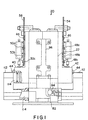
- the present invention is a diode laser pumped solid state laser gain module 20 as illustrated in Fig. 1.
- the laser gain module 20 comprises a housing 22 formed of a ceramic material.
- the housing material is preferably alumina which provides highly advantageous thermal, contanimation, mechanical and optical properties.
- Alumina has a high thermal conductivity which minimizes thermal gradients and associated mechanical distortion caused by the absorption of radiation during pumping.
- alumina has a very low coefficient of thermal expansion to ensure dimensional stability at high temperatures.
- Alumina also minimizes heat input to the housing 22.
- Alumina also has a high stiffness to enable the laser gain module 20 to maintain close tolerances under highly stressful operating conditions.
- Reference surfaces are preferably provided in the housing 22 to enable the accurate positioning of the individual components of the laser gain module 20 during assembly.
- alumina is a diffuse reflector of light and has a relatively low absorption of the light at the wavelengths of interest. This minimizes the possibility of parasitic laser oscillations, which are stray light waves that can interfere with the operation of the laser gain module 20.
- Alumina overcomes the problem of ablation by parasitics as in the known metallic housings, and prevents the destruction of the laser gain medium by the deposition of such ablated metal.
- a slab of a laser gain medium 24 is positioned within the laser cavity defined within the housing 22.
- the laser gain medium 24 has a rectangular cross-section and is vertically oriented in the laser gain module 20.
- the laser gain medium comprises a top face 26, a bottom face 28, opposed major side faces 30, 32, and opposed end faces (not shown).
- the side faces 30, 32 and the end faces are preferably optically polished.
- the end faces are preferably formed at a non-perpendicular angle to the side faces 30, 32, so that light travels longitudinally in a zig-zag pattern through the laser gain medium 24.
- the laser gain medium 24 absorbs radiation from an optical pumping source to create a population inversion of excited species, from which the excited species make a laser transition to produce a laser output.
- the laser gain medium 24 is preferably a crystal of neodymium yttrium aluminum garnet (Nd:YAG) which emits at a major wavelength of 1064 nm.
- Nd:YAG neodymium yttrium aluminum garnet
- Other suitable laser gain materials such as Yb:YAG, Nd:Glass and Ti:Sapphire may optionally be used.
- the radiation source for pumping the laser gain medium 24 preferably comprises a plurality of diode lasers arranged in arrays.
- the light output of the diode laser arrays can be accurately tuned to the absorption line of the active species in the laser gain medium 24 to achieve a high pumping efficiency, and to minimize detrimental heating effects.
- the diode laser arrays preferably emit radiation at the wavelength range of 804 nm to 808 nm to pump the laser gain medium 24.
- the Nd:YAG laser gain medium 24 reemits a laser output at a wavelength of 1064 nm.
- a pair of diode laser manifolds 40, 42 are disposed on opposite sides of the laser gain module 20.
- the diode laser manifolds 40, 42 are mounted to the housing 22 by fasteners such as the elongated threaded fastening elements 44, 46.
- a plurality of individual diode lasers 48a, 48b, 48c are mounted to the diode laser manifold 40.
- a plurality of diode lasers 50a, 50b and 50c (Fig. 2) (collectively referred to herein as the diode laser array 50) are mounted to the opposite diode laser manifold 42.
- the individual diode lasers of the diode laser arrays 48, 50 are preferably substantially uniformly spaced from each other as shown. As illustrated in Fig. 2, the diode lasers extend into the laser cavity, proximate to the laser gain medium 24.
- the diode lasers 48a, 48c, and 50a, 50c extend into the laser cavity at an angle with the horizontal. This arrangement and orientation of the individual diode lasers provides uniform pumping of the major side faces 30, 32 of the laser gain medium 24. Other arrangements and orientations of the diode laser arrays 48, 50 may be used. Furthermore, in some instances only a single diode laser array such as the diode laser array 48 or 50 may be provided to optically pump only one major side face of the laser gain medium 24.
- electrical power is distributed to power connections 52 associated with the diode laser arrays 48, 50 by a plurality of diode laser power busbars 54 (Fig. 4), 56 (Fig 1).
- laser pumping sources such as flashlamps may optionally be used to radiate the laser gain medium 24.
- the diode laser manifolds 40, 42 are formed of a plastic material.
- the diode laser manifolds 40, 42 preferably comprise a three-layer construction of solvent bonded plastic having an electrostatic discharge coating. This multi-layer construction is simple and inexpensive to manufacture. Unlike the known metallic cooling systems, the plastic material is contamination free. The plastic material also is lightweight, yet it provides a high mechanical stiffness. Furthermore, the plastic material is not affected by the 804 nm to 808 nm radiation emitted by the diode laser arrays 48, 50, or the 1064 nm wavelength laser output. The coated plastic material also eliminates static build-up, when properly grounded, that is damaging to diode lasers.
- a pair of generally rectangular shaped windows 58, 60 are disposed on opposite sides of the laser gain medium 24, between the laser gain medium 24 and the diode laser arrays 48, 50.
- the windows 58, 60 are adjacent and parallel to the laser gain medium 24 so as to doline coolant flow channels 62, 64, through which a coolant is flowed longitudinally over the major side faces 30, 32 of the laser gain medium 24.
- the windows 58, 60 are preferably composed of sapphire.
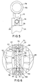
- Sapphire has a coefficient of thermal expansion which closely matches that of the alumina housing 22 to enable the windows 58, 60 to be glass brazed ("fritted") to the housing 22 as indicated at 59 in Fig. 6.
- Other suitable materials having thermal expansion properties close to those of sapphire may optionally be used.
- An anti-reflective coating is applied to the windows 58, 60 to transmit the 804 nm to 808 nm wavelength radiation emitted by the diode laser arrays 48, 50, to enable optical pumping of the laser gain medium 24 through a housing opening 23 adjacent to each of the windows 58, 60 (only one housing opening 23 is shown in Fig. 3).
- Fritting of the sapphire windows 58, 60 to the alumina housing 22 eliminates the need for extra fluid seals or bonded joints in the flow channels 62, 64. Such seals and joints are a potential source of fluid leaks. Fritting also eliminates complex fluid passage configurations and the use of seal mounts in the fragile sapphire windows 58, 60. Fritting further simplifies the final assembly of the laser gain module 20 as the windows 58, 60 are pre-mounted to the housing 22.
- seals 66, 68 are positioned at the upper and lower faces of the windows 58, 60, respectively, to seal the laser gain medium 24 as coolant is passed through the flow channels 62, 64.
- the seals 66, 68 are preferably composed of a pure silicone rubber material that transmits the 804 nm to 808 nm radiation produced by the diode laser arrays 48, 50, and the 1064 nm laser output of the laser gain module 20.
- the seals 66, 68 may optionally be formed of other suitable light transmitting materials. By transmitting these light wavelengths, damaging heating of the seals 66, 68 is avoided.
- the seals 66, 68 are carefully positioned with respect to the laser gain medium 24 to minimize thermal gradients in the laser gain medium 24 that degrade optical performance.
- An upper edge control bar 70 and a lower edge control but 72 are provided to control the edge temperature and, accordingly, the temperature uniformity of the laser gain modium 24.
- the upper edge control bar 70 is positioned adjacent to the top face 26 of the laser gain medium 24 and the lower edge control bar 72 is positioned adjacent to the bottom face 28.
- the edge control bars 70, 72 each provide both heating and cooling capabilities to enable thermal control of the laser gain medium 24 by the addition and removal of heat to compliment the heating produced by the diode laser arrays 48, 50.
- the edge control bars 70, 72 each include a flow channel 74 for flowing a coolant over the top face 26 and the bottom face 28 of the laser gain medium 24, and a heating element 76.
- Fig. 5 illustrates the upper edge control bar 70 in greater detail.
- the lower edge control bar 72 has the same construction and is not illustrated for simplicity.
- the flow channel 74 is spaced from the heating element 76 by a thermal resistor 77 which provides a specific thermal resistance.
- the edge control bar 70 is bonded to the top face 26 and bottom face 28, respectively, of the laser gain medium 24 by an adhesive 79.
- the preferred adhesive is barium oxide-loaded silicone rubber RTV which provides diffuse reflection and minimal absorption at the light wavelengths of 804 nm to 808 nm and 1064 nm; resistance to thermal damage; and good thermal conductivity between the edge control bars 70, 72 and the laser gain medium 24 to prevent local heating.
- Other adhesives may provide similar properties.
- other oxides of metals used as fillers provide similar optical and thermal properties.
- upper heat shields 78 and lower heat shields 80 are provided to contain stray light within the laser cavity of the laser gain module 20.
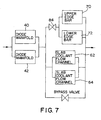
- the laser gain module 20 comprises a coolant distribution system to distribute coolant to the coolant flow channels 62, 64 between the respective windows 58, 60 and the laser gain medium 24; to the edge control bars 70, 72; and to diode laser manifold coolant passages for cooling the diode laser arrays 48, 50 as described below.
- the distribution of coolant to these loads is depicted in Fig. 7.
- the coolant is preferably water and other suitable coolant fluids may optionally be used.
- the coolant distribution system comprises a metallic coolant distribution base 82 and a coolant control valve 84 for adjusting the supply of coolant to the edge control bars 70, 72.
- a flow control valve 120 is provided at the front of the laser gain module 20 to control flow into the coolant flow channels 62, 64.
- the coolant distributing system has a compact construction and comprises a single input and a single output port.
- An edge control bar coolant supply manifold 86 is mounted to the edge control bars 70, 72 above the coolant distribution base 82. As shown in Fig. 3, the edge control bar coolant supply manifold 86 defines a coolant supply passage 88 through which coolant is flowed to the lower edge control bar 72 and to the upper edge control bar 70.
- the edge control bars 70, 72 are each seated at their opposite ends in a pair of flanges which also act as self-fixturing guides 90, 92.
- Spring clamps 94 are provided for exerting a spring force on the self-fixturing guides 90, 92 during assembly.
- the guides 90 are fastened to the edge control bar coolant supply manifold 86 using conventional fasteners such as screws 96.
- the guides 92 are fastened to an edge control bar return manifold 98 by screws 96. Coolant is passed through the edge control bars 70, 72 to cool the upper face 26 and the lower face 28 of the laser gain medium 24, and then returned to the coolant distribution base 82 through a fluid return passage 100 formed in the edge control bar return manifold 98, as represented by arrows.
- the coolant is also flowed through a laser gain medium coolant supply 102 and returned through a laser gain medium coolant return 104.
- An end cap 106 engages an elongated fastener 108 and closes the upper end of the laser gain medium coolant supply 102.
- An end cap 110 closes the upper end of the laser gain medium coolant return 104.
- the coolant is flowed longitudinally through the coolant flow channels 62, 64 between the respective windows 58, 60 and the laser gain medium 24 to cool the major side faces 30, 32 of the laser gain medium 24, and the coolant is then returned to the coolant supply source through the laser gain medium return 104.
- Coolant is also distributed to cool the laser diode arrays 48, 50.
- the coolant distribution system comprises a diode laser manifold coolant supply feed 112 which defines a supply feed passage 114 (see Fig. 1) through which the coolant is flowed to the diode laser manifolds 40, 42, and a diode laser manifold coolant return feed 116 defining a return feed passage (not shown) through which the coolant is returned to the coolant distribution base 82.
- the manifold coolant supply feed 112 and the manifold coolant return feed 116 are typically formed of metal.
- the coolant is distributed within the diode laser manifolds 40, 42 to cool each of the laser diodes of the diode laser arrays 48, 50.
- the laser gain module 20 has a compact, simple construction which provides a high level of support and thermal control of the laser gain medium 24 to maintain beam alignment in the laser cavity.
- Alumina overcomes the problem of metal ablation and associated laser gain medium failure, and allows the use of glass brazing to the sapphire windows 58, 60.
- the housing 22 also provides accurate support of the diode laser arrays 48, 50 to ensure consistent optical pumping of the laser gain medium 24.
- the alumina housing 22 reduces cooling demands and allows the use of a simplified coolant distribution system to distribute coolant to the laser gain medium 24 and to the diode laser manifolds 40, 42, with the isolation of coolant from the diode pump arrays 48, 50.
- the coolant distribution system also eliminates the problem of contamination due to metallic spalling and corrosion.
- the laser gain module 20 maintains a substantially uniform temperature distribution in the laser gain medium along the vertical direction to increase beam quality.
- the materials used to construct the laser gain module 20 are not adversely affected by, and do not specularly reflect, the light wavelengths of 804 nm to 808 nm, and 1064 nm.
Landscapes
- Physics & Mathematics (AREA)
- Electromagnetism (AREA)
- Engineering & Computer Science (AREA)
- Plasma & Fusion (AREA)
- Optics & Photonics (AREA)
- Lasers (AREA)
Claims (14)
- Laserdiodengepumptes Festkörper-Plattenlaserverstärkermodul (20) zum Erzeugen eines Ausgangsstrahls, aufweisend:ein Laserverstärkermedium (24) mit einer oberen Fläche (26), einer unteren Fläche (28) und einem Paar einander gegenüberliegenden Seitenflächen (30, 32);Pumpmittel, die nahe mindestens einer der Seitenflächen (30, 32) angeordnet sind, um das Laserverstärkermedium (24) zu bestrahlen und einen Ausgangsstrahl zu erzeugen;Mittel zum Kühlen des Laserverstärkermediums (24), um eine im Wesentlichen gleichmäßige Temperaturverteilung zwischen der unteren Fläche (28) und der oberen Fläche (26) zu erzeugen; undMittel (40, 42) zum Kühlen jedes der Pumpmittel, dadurch gekennzeichnet, dass es ferner ein Keramikgehäuse (22) aufweist, in dem das Laserverstärkermedium (24) angeordnet und vom Keramikgehäuse (22) getragen wird, und das Keramikgehäuse (22) aus Aluminiumoxid besteht, das ein diffuser Lichtreflektor ist und eine geringe Absorption bei den vom Laserverstärkermedium (24) und den Pumpmitteln emittierten Wellenlängen hat.
- Laserverstärkermodul nach Anspruch 1, dadurch gekennzeichnet, dass die Pumpmittel eine Laserdiodenmatrix (48a, 48b, 48c, 50a, 50b, 50c) aufweisen, die nahe jeder der Seitenflächen (30, 32) angeordnet ist, um das Laserverstärkermedium (24) zu bestrahlen.
- Laserverstärkermodul nach Anspruch 2, dadurch gekennzeichnet, dass jede der Laserdiodenmatrizen (48a, 48b, 48c, 50a, 50b, 50c) an einem am Gehäuse (22) angebauten Laserdiodenverteiler (40, 42) angebracht sind, und jeder der Laserdiodenverteiler (40, 42) aus einem Kunststoffmaterial mit einer elektrostatischen Beschichtung darauf besteht.
- Laserverstärkermodul nach Anspruch 3, dadurch gekennzeichnet, dass es ferner Mittel (112, 114) zur Lieferung von Kühlmittel an jeden der Laserdiodenverteiler (40, 42) aufweist, um die Laserdiodenmatrizen (48a, 48b, 48c, 50a, 50b, 50c) zu kühlen.
- Laserverstärkermodul nach Anspruch 3 oder 4, dadurch gekennzeichnet, dass jeder der Laserdiodenverteiler (40, 42) eine Mehrzahl Lagen eines Kunststoffmaterials aufweist, die einen Aufbau mit Lösungsmittelbindung oder einem anderen Klebeverfahren haben.
- Laserverstärkermodul nach einem der Ansprüche 1 bis 5, dadurch gekennzeichnet, dass die Mittel zur Kühlung des Laserverstärkermediums (24) Mittel (58, 60, 62, 64) aufweisen, die ein Kühlmittel über jede der Seitenflächen (30, 32) fließen lassen.
- Laserverstärkermodul nach Anspruch 6, bei dem die Mittel (58, 60, 62, 64), die das Kühlmittel über jede der Seitenflächen (30, 32) fließen lassen, ein Paar Fenster (58, 60) aufweisen, wobei jedes der Fenster (58, 60) nahe und parallel zu einer der Seitenflächen (30, 32) angeordnet ist, so dass es einen Kühlmittelkanal (62, 64) definiert, durch den das Kühlmittel fließt, sowie Dichtmittel zum Abdichten des Laserverstärkermediums (24); oder bei dem die Fenster (58, 60) aus Saphir mit einer antireflektiven Beschichtung darauf für die Übertragung der von den Pumpmitteln emittierten Strahlung bestehen; oder bei dem die Fenster (58, 60) am Gehäuse (22) gefrittet sind.
- Laserverstärkermodul nach Anspruch 7, dadurch gekennzeichnet, dass die Dichtmittel ein Paar Dichtungen (66, 68) aus Silikonkautschuk aufweisen, der bei den vom Laserverstärkermediums (24) und den Pumpmitteln emittierten Strahlung optisch durchsichtig ist, und jede der Dichtungen (66, 68) zwischen einem der Fenster (58, 60) und dem Laserverstärkermedium (24) angeordnet ist.
- Laserverstärkermodul nach einem der Ansprüche 1 bis 8, dadurch gekennzeichnet, dass das Laserverstärkermedium (24) aus kristallinem Nd:YAG besteht.
- Laserverstärkermodul nach einem der Ansprüche 1 bis 9, dadurch gekennzeichnet, dass die Pumpmittel eine Strahlung mit einer Wellenlänge von 804 nm bis 808 nm emittieren.
- Laserverstärkermodul nach einem der Ansprüche 1 bis 10, dadurch gekennzeichnet, dass es ferner Mittel zur Wärmeregelung aufweist, die nahe der oberen Fläche (26) und der unteren Fläche (28) angeordnet sind, um die obere Fläche (26) und die untere Fläche (28) wahlweise zu erwärmen oder zu kühlen.
- Laserverstärkermodul nach Anspruch 11, dadurch gekennzeichnet, dass die Mittel zur Wärmeregelung ein Begrenzungsprofil (70) an der Oberkante nahe der oberen Fläche (26) und eine Begrenzungsprofil (72) an der Unterkante nahe der unteren Fläche (28) aufweisen, wobei das Begrenzungsprofil (70) an der Oberkante und das Begrenzungsprofil (72) an der Unterkante jeweils einen Kühlmittelkanal (74) begrenzen, durch den Kühlmittel fließt, und wobei das Begrenzungsprofil (70) an der Oberkante und das Begrenzungsprofil (72) an der Unterkante jeweils ein Heizmittel (76) aufweisen, um die obere Fläche (26) bzw. die untere Fläche (28) wahlweise zu erwärmen.
- Laserverstärkermodul nach Anspruch 12, dadurch gekennzeichnet, dass das Begrenzungsprofil (70) an der Oberkante und das Begrenzungsprofil (72) an der Unterkante mit der oberen Fläche (26) bzw. mit der unteren Fläche (28) mittels eines mit Metalloxid befrachteten Silikonkautschuks oder eines anderen wärmeleitfähigen Klebers verbunden sind.
- Laserverstärkermodul nach Anspruch 13, dadurch gekennzeichnet, dass der mit Metalloxid befrachtete Silikonkautschuk ein mit Silikonkautschuk mit Bariumoxid befrachteter Silikonkautschuk ist.
Applications Claiming Priority (2)
| Application Number | Priority Date | Filing Date | Title |
|---|---|---|---|
| US683585 | 1996-07-15 | ||
| US08/683,585 US5790575A (en) | 1996-07-15 | 1996-07-15 | Diode laser pumped solid state laser gain module |
Publications (3)
| Publication Number | Publication Date |
|---|---|
| EP0820126A2 EP0820126A2 (de) | 1998-01-21 |
| EP0820126A3 EP0820126A3 (de) | 1999-11-17 |
| EP0820126B1 true EP0820126B1 (de) | 2004-09-22 |
Family
ID=24744662
Family Applications (1)
| Application Number | Title | Priority Date | Filing Date |
|---|---|---|---|
| EP97112035A Expired - Lifetime EP0820126B1 (de) | 1996-07-15 | 1997-07-15 | Laserdiodengepumpter Festkörperlasermodul |
Country Status (5)
| Country | Link |
|---|---|
| US (1) | US5790575A (de) |
| EP (1) | EP0820126B1 (de) |
| JP (1) | JP3059952B2 (de) |
| CN (1) | CN1084065C (de) |
| DE (1) | DE69730784T2 (de) |
Families Citing this family (28)
| Publication number | Priority date | Publication date | Assignee | Title |
|---|---|---|---|---|
| JP3067686B2 (ja) * | 1997-04-21 | 2000-07-17 | 日本電気株式会社 | 固体レーザ装置 |
| US6034977A (en) * | 1998-02-17 | 2000-03-07 | Trw Inc. | Optical path difference control system and method for solid state lasers |
| US6052396A (en) * | 1998-02-19 | 2000-04-18 | Trw Inc. | Thermal radiation shield for laser gain module |
| DE19840926B4 (de) * | 1998-09-08 | 2013-07-11 | Hell Gravure Systems Gmbh & Co. Kg | Anordnung zur Materialbearbeitung mittels Laserstrahlen und deren Verwendung |
| US6301277B1 (en) * | 1998-11-20 | 2001-10-09 | Trw Inc. | Solid state laser master oscillator gain module |
| US20060249491A1 (en) * | 1999-09-01 | 2006-11-09 | Hell Gravure Systems Gmbh | Laser radiation source |
| JP4450524B2 (ja) * | 2001-02-27 | 2010-04-14 | 株式会社Ihi | 固体レーザ装置 |
| US6690696B2 (en) * | 2002-06-14 | 2004-02-10 | Raytheon Company | Laser cooling apparatus and method |
| JP3897045B2 (ja) * | 2003-03-17 | 2007-03-22 | 三菱電機株式会社 | レーザ発振器 |
| US7170919B2 (en) * | 2003-06-23 | 2007-01-30 | Northrop Grumman Corporation | Diode-pumped solid-state laser gain module |
| US20050078714A1 (en) * | 2003-10-08 | 2005-04-14 | Hiroshi Komine | High power fiber laser with eye safe wavelengths |
| US20060279793A1 (en) * | 2004-07-30 | 2006-12-14 | Hell Gravure Systems Gmbh | Printing form processing with a plurality of engraving tool tracks forming lines |
| CN101719618B (zh) * | 2009-12-23 | 2011-03-30 | 清华大学 | 一种改善非对称散热板条型激光器热焦距不对称的装置 |
| EP2534672B1 (de) | 2010-02-09 | 2016-06-01 | Energetiq Technology Inc. | Laserbetriebene lichtquelle |
| KR20150064114A (ko) * | 2010-09-15 | 2015-06-10 | 바이오레이즈, 인크. | 전자기 방사선을 이용한 고전력원 |
| US9225148B2 (en) | 2010-09-23 | 2015-12-29 | Daylight Solutions, Inc. | Laser source assembly with thermal control and mechanically stable mounting |
| CN102136672B (zh) * | 2011-03-15 | 2012-12-26 | 上海交通大学 | 基于碳化硅包层板条的激光器冷却装置 |
| CN103794971B (zh) * | 2014-02-26 | 2016-04-20 | 哈尔滨工业大学 | 一种晶体口径可调节的高精度温度控制装置 |
| CN104953446A (zh) * | 2014-03-28 | 2015-09-30 | 中国科学院大连化学物理研究所 | 一种新型二极管泵浦浸入式液冷固体激光器增益池 |
| CN104218436A (zh) * | 2014-09-26 | 2014-12-17 | 中国科学院上海光学精密机械研究所 | 基于蓝宝石包层的片状钕玻璃激光放大器的冷却装置 |
| JP6736127B2 (ja) * | 2016-08-23 | 2020-08-05 | 株式会社ブイ・テクノロジー | レーザポンプチャンバ装置 |
| JP7279600B2 (ja) * | 2019-09-26 | 2023-05-23 | ブラザー工業株式会社 | レーザ加工装置 |
| US11587781B2 (en) | 2021-05-24 | 2023-02-21 | Hamamatsu Photonics K.K. | Laser-driven light source with electrodeless ignition |
| US12165856B2 (en) | 2022-02-21 | 2024-12-10 | Hamamatsu Photonics K.K. | Inductively coupled plasma light source |
| US12144072B2 (en) | 2022-03-29 | 2024-11-12 | Hamamatsu Photonics K.K. | All-optical laser-driven light source with electrodeless ignition |
| US12156322B2 (en) | 2022-12-08 | 2024-11-26 | Hamamatsu Photonics K.K. | Inductively coupled plasma light source with switched power supply |
| US12578076B2 (en) | 2023-06-05 | 2026-03-17 | Hamamatsu Photonics K.K. | Dual-output laser-driven light source |
| CN120638018A (zh) * | 2025-06-19 | 2025-09-12 | 中国科学院合肥物质科学研究院 | 一种用于OHx探测的大能量板条激光器散热系统 |
Family Cites Families (11)
| Publication number | Priority date | Publication date | Assignee | Title |
|---|---|---|---|---|
| US4378601A (en) * | 1980-12-22 | 1983-03-29 | The Board Of Trustees Of The Leland Stanford Junior University | Slab and holder for face pumped slab laser |
| US4525842A (en) * | 1984-02-24 | 1985-06-25 | Myers John D | Laser device and method |
| US4852109A (en) * | 1988-12-02 | 1989-07-25 | General Electric Company | Temperature control of a solid state face pumped laser slab by an active siderail |
| DE3843015A1 (de) * | 1988-12-21 | 1990-06-28 | Hoechst Ceram Tec Ag | Laserresonator |
| US5107091A (en) * | 1990-09-14 | 1992-04-21 | Applied Solar Energy Corporation | Laser diode array mounting module |
| US5311528A (en) * | 1991-08-30 | 1994-05-10 | Hoya Corporation | Solid-state laser device capable of stably producing an output laser beam at high power |
| US5291504A (en) * | 1992-02-18 | 1994-03-01 | Fibertek, Inc. | Laser pump module |
| DE4303956C2 (de) * | 1993-02-10 | 1995-06-01 | Langner Walter | Laser |
| US5555254A (en) * | 1993-11-05 | 1996-09-10 | Trw Inc. | High brightness solid-state laser with zig-zag amplifier |
| US5394427A (en) * | 1994-04-29 | 1995-02-28 | Cutting Edge Optronics, Inc. | Housing for a slab laser pumped by a close-coupled light source |
| US5475702A (en) * | 1994-05-31 | 1995-12-12 | General Electric Company | Diode pumped slab module |
-
1996
- 1996-07-15 US US08/683,585 patent/US5790575A/en not_active Expired - Lifetime
-
1997
- 1997-07-10 JP JP9185466A patent/JP3059952B2/ja not_active Expired - Fee Related
- 1997-07-14 CN CN97114614.4A patent/CN1084065C/zh not_active Expired - Fee Related
- 1997-07-15 DE DE69730784T patent/DE69730784T2/de not_active Expired - Fee Related
- 1997-07-15 EP EP97112035A patent/EP0820126B1/de not_active Expired - Lifetime
Also Published As
| Publication number | Publication date |
|---|---|
| JP3059952B2 (ja) | 2000-07-04 |
| DE69730784T2 (de) | 2005-02-10 |
| JPH1093169A (ja) | 1998-04-10 |
| DE69730784D1 (de) | 2004-10-28 |
| US5790575A (en) | 1998-08-04 |
| CN1181649A (zh) | 1998-05-13 |
| CN1084065C (zh) | 2002-05-01 |
| EP0820126A2 (de) | 1998-01-21 |
| EP0820126A3 (de) | 1999-11-17 |
Similar Documents
| Publication | Publication Date | Title |
|---|---|---|
| US5790575A (en) | Diode laser pumped solid state laser gain module | |
| US5394427A (en) | Housing for a slab laser pumped by a close-coupled light source | |
| US5084886A (en) | Side-pumped laser system with independent heat controls | |
| EP1514332B1 (de) | Laserkühlungsvorrichtung und verfahren | |
| US6339605B1 (en) | Active mirror amplifier system and method for a high-average power laser system | |
| US5105429A (en) | Modular package for cooling a laser diode array | |
| JP4959925B2 (ja) | ダイオードポンプ固体ディスクレーザおよび均一なレーザ利得を生成する方法 | |
| US4852109A (en) | Temperature control of a solid state face pumped laser slab by an active siderail | |
| EP0903819B1 (de) | Optisch gepumpter Laser | |
| US20170316963A1 (en) | Direct optical heating of substrates | |
| EP1196969A1 (de) | Laserkristallvorrichtung | |
| US6118804A (en) | Laser amplification system | |
| EP1003252A2 (de) | Festkörperlasermodul für Hauptoszillator | |
| US5900967A (en) | Laser diode mounting technique to evenly deposit energy | |
| JPH1117252A (ja) | 半導体励起固体レーザ装置 | |
| EP2534738B1 (de) | Scheibenlaser | |
| US7949022B2 (en) | Diode pumping of a laser gain medium | |
| JP3237525B2 (ja) | 固体レーザ励起モジュール | |
| TW200415612A (en) | Multiple-disk laser system | |
| US20170373457A1 (en) | Waveguide for diode-pumped alkali lasers | |
| US5781580A (en) | Diode pumping module | |
| EP1670104B1 (de) | Mit einem festkörperlaser gepumptes modul und laseroszillator | |
| US20230411921A1 (en) | Coefficient of thermal expansion matched mounting technique for high power laser | |
| JPH10223945A (ja) | 面冷却式高出力レーザ光学セル | |
| US7508855B2 (en) | Compact high output power mid-infrared emitter system and method |
Legal Events
| Date | Code | Title | Description |
|---|---|---|---|
| PUAI | Public reference made under article 153(3) epc to a published international application that has entered the european phase |
Free format text: ORIGINAL CODE: 0009012 |
|
| AK | Designated contracting states |
Kind code of ref document: A2 Designated state(s): DE FR GB |
|
| PUAL | Search report despatched |
Free format text: ORIGINAL CODE: 0009013 |
|
| AK | Designated contracting states |
Kind code of ref document: A3 Designated state(s): AT BE CH DE DK ES FI FR GB GR IE IT LI LU MC NL PT SE |
|
| 17P | Request for examination filed |
Effective date: 19991210 |
|
| AKX | Designation fees paid |
Free format text: DE FR GB |
|
| 17Q | First examination report despatched |
Effective date: 20020422 |
|
| RAP1 | Party data changed (applicant data changed or rights of an application transferred) |
Owner name: NORTHROP GRUMMAN CORPORATION |
|
| RAP1 | Party data changed (applicant data changed or rights of an application transferred) |
Owner name: NORTHROP GRUMMAN CORPORATION |
|
| GRAP | Despatch of communication of intention to grant a patent |
Free format text: ORIGINAL CODE: EPIDOSNIGR1 |
|
| GRAS | Grant fee paid |
Free format text: ORIGINAL CODE: EPIDOSNIGR3 |
|
| GRAA | (expected) grant |
Free format text: ORIGINAL CODE: 0009210 |
|
| AK | Designated contracting states |
Kind code of ref document: B1 Designated state(s): DE FR GB |
|
| REG | Reference to a national code |
Ref country code: GB Ref legal event code: FG4D |
|
| REF | Corresponds to: |
Ref document number: 69730784 Country of ref document: DE Date of ref document: 20041028 Kind code of ref document: P |
|
| PGFP | Annual fee paid to national office [announced via postgrant information from national office to epo] |
Ref country code: FR Payment date: 20050718 Year of fee payment: 9 |
|
| PLBE | No opposition filed within time limit |
Free format text: ORIGINAL CODE: 0009261 |
|
| STAA | Information on the status of an ep patent application or granted ep patent |
Free format text: STATUS: NO OPPOSITION FILED WITHIN TIME LIMIT |
|
| ET | Fr: translation filed | ||
| 26N | No opposition filed |
Effective date: 20050623 |
|
| PGFP | Annual fee paid to national office [announced via postgrant information from national office to epo] |
Ref country code: GB Payment date: 20060726 Year of fee payment: 10 |
|
| REG | Reference to a national code |
Ref country code: FR Ref legal event code: ST Effective date: 20070330 |
|
| GBPC | Gb: european patent ceased through non-payment of renewal fee |
Effective date: 20070715 |
|
| PG25 | Lapsed in a contracting state [announced via postgrant information from national office to epo] |
Ref country code: FR Free format text: LAPSE BECAUSE OF NON-PAYMENT OF DUE FEES Effective date: 20060731 |
|
| PG25 | Lapsed in a contracting state [announced via postgrant information from national office to epo] |
Ref country code: GB Free format text: LAPSE BECAUSE OF NON-PAYMENT OF DUE FEES Effective date: 20070715 |
|
| PGFP | Annual fee paid to national office [announced via postgrant information from national office to epo] |
Ref country code: DE Payment date: 20080722 Year of fee payment: 12 |
|
| PG25 | Lapsed in a contracting state [announced via postgrant information from national office to epo] |
Ref country code: DE Free format text: LAPSE BECAUSE OF NON-PAYMENT OF DUE FEES Effective date: 20100202 |