EP1514332B1 - Laserkühlungsvorrichtung und verfahren - Google Patents
Laserkühlungsvorrichtung und verfahren Download PDFInfo
- Publication number
- EP1514332B1 EP1514332B1 EP03737033A EP03737033A EP1514332B1 EP 1514332 B1 EP1514332 B1 EP 1514332B1 EP 03737033 A EP03737033 A EP 03737033A EP 03737033 A EP03737033 A EP 03737033A EP 1514332 B1 EP1514332 B1 EP 1514332B1
- Authority
- EP
- European Patent Office
- Prior art keywords
- manifold
- laser
- slab
- cooling
- fluorescent energy
- Prior art date
- Legal status (The legal status is an assumption and is not a legal conclusion. Google has not performed a legal analysis and makes no representation as to the accuracy of the status listed.)
- Expired - Lifetime
Links
Images


Classifications
-
- H—ELECTRICITY
- H01—ELECTRIC ELEMENTS
- H01S—DEVICES USING THE PROCESS OF LIGHT AMPLIFICATION BY STIMULATED EMISSION OF RADIATION [LASER] TO AMPLIFY OR GENERATE LIGHT; DEVICES USING STIMULATED EMISSION OF ELECTROMAGNETIC RADIATION IN WAVE RANGES OTHER THAN OPTICAL
- H01S3/00—Lasers, i.e. devices using stimulated emission of electromagnetic radiation in the infrared, visible or ultraviolet wave range
- H01S3/02—Constructional details
- H01S3/04—Arrangements for thermal management
-
- H—ELECTRICITY
- H01—ELECTRIC ELEMENTS
- H01S—DEVICES USING THE PROCESS OF LIGHT AMPLIFICATION BY STIMULATED EMISSION OF RADIATION [LASER] TO AMPLIFY OR GENERATE LIGHT; DEVICES USING STIMULATED EMISSION OF ELECTROMAGNETIC RADIATION IN WAVE RANGES OTHER THAN OPTICAL
- H01S3/00—Lasers, i.e. devices using stimulated emission of electromagnetic radiation in the infrared, visible or ultraviolet wave range
- H01S3/02—Constructional details
- H01S3/04—Arrangements for thermal management
- H01S3/042—Arrangements for thermal management for solid state lasers
-
- H—ELECTRICITY
- H01—ELECTRIC ELEMENTS
- H01S—DEVICES USING THE PROCESS OF LIGHT AMPLIFICATION BY STIMULATED EMISSION OF RADIATION [LASER] TO AMPLIFY OR GENERATE LIGHT; DEVICES USING STIMULATED EMISSION OF ELECTROMAGNETIC RADIATION IN WAVE RANGES OTHER THAN OPTICAL
- H01S3/00—Lasers, i.e. devices using stimulated emission of electromagnetic radiation in the infrared, visible or ultraviolet wave range
- H01S3/09—Processes or apparatus for excitation, e.g. pumping
- H01S3/091—Processes or apparatus for excitation, e.g. pumping using optical pumping
- H01S3/094—Processes or apparatus for excitation, e.g. pumping using optical pumping by coherent light
- H01S3/0941—Processes or apparatus for excitation, e.g. pumping using optical pumping by coherent light of a laser diode
Definitions
- the present invention relates to lasers. More specifically, the present invention relates to systems and methods for cooling solid-state laser media.
- Sensible heat is energy that is conducted through the surface while fluorescence is waste light that is created within the medium.
- Sensible heat is produced by non-radiative processes in the laser medium that enable relaxation of the excited species, which may be rare-earth ions in a crystal, from a higher energy level to a lower energy level.
- An unavoidable portion of the sensible heat is due to the "quantum defect" which is the difference in photon energy between the pump light and the laser light.
- Other processes may contribute to the sensible heat, uncluding phonon-assisted quenching of the upper state population by intermediate energy levels, upconversion and subsequent non-radiative relaxation, and ground-state absorbtion.
- Fluorescent light is an omni-directional spontaneous emission resulting from incomplete extraction by the laser beam of the energy stored in a population inversion. Fluorescent light does not create heat until it impinges upon a surface and is absorbed.
- Waste energy is particularly problematic with respect to solid-state lasers. That is, chemical lasers, gas lasers, and liquid medium lasers, such as dyes, have a lasing medium which may be caused to flow out of the active region of the laser cavity for cooling.
- Solid-state lasers typically have a stationary lasing medium, which does not allow heat removal by forced convection of the lasing medium. That is, once the medium is heated with pump energy, it cannot simply be removed from the pump cavity for cooling. Unfortunately, failure to successfully remove heat from solid-state lasers will cause the temperature of the medium to substantially increase, and may degrade the operation of the laser and reduce its reliability.
- the sensible heat may be transported through the thin dimension to the slab's surfaces by conduction without incurring excessive temperature drops.
- the radiant energy of spontaneous emission must also be rejected.
- the energy of the fluorescent radiation component may exceed that of the sensible heat component by a factor of four.
- WO 03/043145 by A. Betin and W. Griffin and entitled SYSTEMS AND METHOD FOR A MULTI-JET IMPINGEMENT COOLED LASER PUMPHEAD (Attorney Docket No. PD-01W090), which comprises part of the state of the art under A.54(3) EPC, discloses and claims an invention which uses liquid-phase multi-jet impingement directly on the broad face of a slab to remove the sensible heat component and either uses an absorbing species in the cooling liquid or an absorbing structure immersed within the cooling manifold to absorb the fluorescent component in a distributed volume at some distance away from the slab face, such that the fluorescent heating does not add to the sensible heat at the slab face.
- This approach provides excellent thermal transfer at the surface, avoids problems associated with nucleate boiling in a 2-phase cooling system and is compatible with a continuously operating high power laser system.
- U.S. 3,518,569 discloses a fixture for supporting a laser rod in a high energy laser system.
- the laser rod is mounted concentrically in a transparent tube and a sheath of liquid is interposed between the rod and the tube.
- the inventive apparatus includes a mechanism for transporting thermal energy from a laser and for communicating fluorescent radiation therefrom as well.
- the apparatus includes an optically transparent cooling structure or manifold with an inlet port, an exhaust port and a plurality of spray nozzles therebetween adapted to direct a cooling fluid on the active medium of a solid-state laser.
- the manifold is constructed of sapphire, notwithstanding the fact that diamond and other optically transparent materials may be used, such that the fluorescent component of waste energy is transmitted as light out of and away from the laser pump cavity (or pumphead).
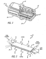
- FIG 1 is a cut-away 3-D solid model view of a multi-jet impingement-cooled slab laser pumphead designed in accordance with the teachings of the above-referenced Betin et al. application.
- the pumphead 10' includes a diffusion-bonded rectangular slab laser medium 20' onto which a cooling fluid is sprayed by two symmetrically disposed multi-jet sprayheads 12'.
- the laser pumphead apparatus consists of an array of jets impinging on the surface of the laser slab with an interspersed array of exhaust holes.
- the diffusion-bonded laser slab is shown more clearly in Figure 2.
- Figure 2 is a simplified representation of a slab laser medium, showing conventional lasing, pumping, and cooling directions thereof.
- Diode pump light is input along one or both ends 24' of the slab 20'.
- the slab is symmetrically pumped from both ends as illustrated in Fig. 2.
- a laser beam is emitted from the ends 24' of the slab 20'.
- the slab 20' is cooled by a removal of thermal energy from the top and bottom surfaces 26' and 28' thereof through the spray of the coolant from a plurality of jets in the multi-jet sprayhead 12' of Figure 1.
- the multi-jet sprayheads 12' may be disposed within an interface or metering plate 14'. Coolant is supplied through an intake manifold 16' and removed through an exhaust manifold 18'. Side exhaust of the coolant may be employed.
- the fluorescence component of waste power from the slab is absorbed within a species dissolved or suspended within the coolant media allowing the conversion from light to heat to occur in a distributed region within the coolant manifold and away from the surface of the slab.
- the fluorescence is absorbed at the surface of a porous structure such as a screen mesh or stack of perforated plates disposed within the coolant manifold, such that the exhaust coolant flows through the mesh, thereby removing the waste power as sensible heat.
- this approach relies on the slab pumphead cooling loop to remove both the sensible and fluorescence components. This places an additional thermal load on the coolant and the associated heat transfer equipment which rejects heat from the coolant, requiring high flow rates and large diameter cooling lines in an already congested volume. This may increase the requirements on the external heat dissipator by a factor of five. For a spaceborne application which rejects heat by radiation to ambient at about 300°K, this increase may become critical.
- the need in the art is addressed by the laser cooling apparatus and method of the present invention.
- the present invention uses essentially the same approach for removing the sensible heat from the surface of the slab via all-liquid phase multi-jet impingement cooling.
- the inventive apparatus further includes a mechanism - an optically transparent manifold - for communicating fluorescent radiation from the slab as well.
- FIG 3 is a simplified diagram showing an illustrative application of the teachings of the present invention.
- the optically transparent manifold 10 is applied around a slab pumphead 20 to remove sensible heat and transmit fluorescent energy therefrom.
- the optically transparent manifold 10 includes an inlet port, an exhaust port and a plurality of spray nozzles therebetween (none of which are shown in Figure 3) adapted to direct a cooling fluid on the active medium of a laser.
- the manifold 10 is coupled to a conventional cooling loop (not shown) to remove sensible heat from the slab pumphead 20 using a multi-jet impingement approach, such as that shown in disclosed in the above-referenced Betin et al. application.
- the transparency of the manifold 10 allows for the fluorescent energy to be more efficiently removed from the system than heretofore possible using conventional teachings.
- the manifold 10 is made from a material that is transparent at the fluorescence wavelength of the laser (e.g., 1.03 ⁇ m for Yb:YAG) thereby allowing the fluorescence component of waste power to pass through a coolant and manifold structure in the form of optical radiation, where it can be removed without adding to the heat load of the laser cooling system. (In a preferred mode, the manifold is constructed of sapphire notwithstanding the fact that diamond and other optically transparent materials may be used.)
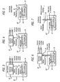
- Figures 3 - 7 depict various arrangements for removing fluorescent energy communicated through the transparent manifold of the present invention.
- Figure 3 depicts a first embodiment by which the fluorescent energy is absorbed by a separate heat sink 40 within a laser system 30.
- a separate heat sink 40 allows for the thermal load associated with the fluorescent energy to be handled more easily, where the heat sink temperature is not constrained by the performance of the laser medium.
- Figure 4 shows an alternative arrangement by which the florescent radiation may be transmitted through an optically transparent window 32' out of the laser system 30' to an external absorptive heat sink structure 40' such as the inside of the aircraft skin or a jet fuel heat exchanger.
- Figure 5 shows yet another alternative arrangement in which the florescent radiation is relayed and transmitted out of the host platform 30" to the external environment.
- This approach is attractive for space based laser systems since it avoids the processes of first converting the fluorescence power to sensible heat, transporting the heat via heat pipes or other means to a thermal radiator panel, and finally converting the waste power back into light as infrared blackbody radiation at the radiator panel.
- Figures 6 and 7 depict additional alternative arrangements by which the fluorescent energy is transported to either an external absorbing heat sink ( Figure 6) or to an external environment ( Figure 7) by a relay optic or light guide (optical fibers or light pipes) 34.
- the adjacent fibers may be sintered to each other, their previously round cross-section assuming a hexagonal or other polygonal form.
- the space left between the fibers should be minimized to limit the fluorescent energy from escaping and landing in an undesired location.
- the remaining lengths of the fibers can be bundled together and routed, in a manner similar to electrical cabling, to a convenient point at which the fluorescent light in the fibers can escape and be dissipated in an external absorber or environment.
- One or more mirrors or refractive elements may also be positioned outside the top and bottom surfaces of the manifold so that the fluorescent light emanating from the manifold may be directed to a desired location.
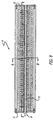
- Figure 8 is a sectional side view of a transparent manifold implemented in accordance with the teachings of the present invention.
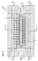
- Figure 9 is a sectional end view of the manifold of Figure 8 taken along the lines B-B' thereof.
- Figure 10 is a magnified sectional side view of a portion of the transparent manifold of Figure 9 taken along the lines A-A' thereof.
- the design requirements of the transparent manifold are different from those described for the manifold of the above-referenced application Betin et al. due to the fact that high intensity light will be passing through the flow manifold. Flow areas and nozzle sizes remain the same however inasmuch as, as described earlier, these design elements depend primarily on the sensible heat dissipated at the external surfaces of the slab.
- the flow manifold may be fabricated as a monolithic structure with no o-ring seals or gaskets to absorb or scatter the fluorescence radiation.
- the manifold 10 is constructed with sections of sapphire which are machined to provide inlets, outlets and channels therein.
- Joining of the various layers may be accomplished by optical bonding techniques, such as chemical bonding, optical contacting, or preferably diffusion bonding. Diffusion bonding of large areas of glass and/or sapphire is now well-established and produces strong and optically-clear interfaces.
- optical bonding techniques such as chemical bonding, optical contacting, or preferably diffusion bonding.
- Diffusion bonding of large areas of glass and/or sapphire is now well-established and produces strong and optically-clear interfaces.
- One practitioner of this art is Onyx Optics, Dublin, CA who holds several fundamental patents in the field.
- the design should avoid sharp edges, sites from which cracks could propagate, and high aspect ratio nozzle configurations, which could break off in handling and under normal vibration/shock loads.
- Nozzle sizes, center-to-center spacing, and placement as well as approximate cross-sections of flow manifolds will be selected in accordance with the teachings of the above referenced Betin et al. application. This is due to the fact that removal of sensible heat from the slab's surface dominates the multi-jet cooling flow, and is only weakly dependent on heat dissipated by the fluorescent energy in the cooling fluid.
- the active core of the slab 20 is shown at 22.
- a cladding 24 surrounds the core 22.
- the cladding 24 allows guiding of the pump and laser light within the core, protects the core 22 from breakage and conducts heat therefrom.
- the flow of coolant around the slab 20 is illustrated in Figure 9. Any conventional coolant may be used such as water, alcohol, ammonia, cryogens (for space applications), mixtures thereof or any other coolant fluid known in the art with suitable thermal capacity and operative at the temperature extremes of the system. Further, those skilled in art will appreciate that a gas may be used as the cooling fluid without departing from the scope of the present teachings.
- coolant flows into one of four inlets 12 through channels 14 to nozzles 16 where it is sprayed on the slab 20.
- the exhaust fluid is received by exhaust channels 18 and exits via exhaust ports 19.
- Reflective metal end plates 21, within which O-ring seals 23 are seated, ensure sealing of the coolant within the manifold 10 and slab 20.
- Figure 11a shows a top view of a monolithic manifold with no exhaust holes.
- Figure 11b is a sectional side view of the manifold of Figure 11a taken along the line A-A thereof.
- the coolant liquid after impinging on the laser slab, is exhausted transversely, preferentially through a series of interconnecting, recessed flow channels machined in the surface of the sapphire.
- the channels form a two-dimensional network with hexagonal symmetry and the jet nozzles are drilled in the mesas left after cutting the channels. All inside and outside corners are rounded to avoid crack initiation and propagation under load.
- the entire plate structure is clamped and sealed around the edges with a face-seal o-ring to the high-pressure inlet manifold cover.
- Figure 12 shows an alternative embodiment for the diffusion-bonded manifold in which the bonded surfaces form a series of parallel exhaust ports.
- the exhaust ports are accessed through exhaust holes drilled through the multi-jet layer. This configuration is more complex than that shown in Figure 11, but provides better control of the exhaust flow with better temperature uniformity across the laser slab's surface.
Landscapes
- Physics & Mathematics (AREA)
- Electromagnetism (AREA)
- Engineering & Computer Science (AREA)
- Plasma & Fusion (AREA)
- Optics & Photonics (AREA)
- Lasers (AREA)
Claims (8)
- Einrichtung zur Kühlung einer Laserplatte (20), wobei die Einrichtung folgendes umfasst:erste Mittel zur Lieferung eines Kühl-Strömungsmittels; undeinen Sammelanschluss (10) zum Anbringen in unmittelbarer Nähe zu der Laserplatte (20), wobei der Sammelanschluss (10) einen Einlass (12) in Strömungsverbindung mit den ersten Mitteln, eine Mehrzahl von Düsen (16) in Verbindung mit dem Einlass (12) zum Aufsprühen des Kühl-Strömungsmittels auf die Laserplatte (20) und eine Auslassöffnung (19) aufweist, um nach dem Aufsprühen des Kühl-Strömungsmittels auf die Laserplatte (20) das Kühl-Strömungsmittel wieder einzusammeln; dadurch gekennzeichnet, dass der Sammelanschluss (10) optisch transparent gegenüber fluoreszenter Energie ist, die durch die Laserplatte (20) abgestrahlt wird.
- Einrichtung nach Anspruch 1, bei welcher die fluoreszente Energie eine Wellenlänge hat, die dem Betrieb eines Lasersystems entspricht, bei welchem die Einrichtung verwendet wird.
- Einrichtung nach Anspruch 1 oder Anspruch 2, bei welcher der Sammelanschluß (10) aus Saphir oder Diamant hergestellt ist.
- Einrichtung nach irgendeinem vorausgehenden Anspruch, welche weiter eine Wärmesenke zum Absorbieren der fluoreszenten Energie aufweist.
- Einrichtung nach irgendeinem vorausgehenden Anspruch, welche weiter eine Relaisoptik oder eine Lichtleitung zum Abtransport der fluoreszenten Energie von der Laserplatte (20) aufweist.
- Einrichtung nach irgendeinem vorausgehenden Anspruch, bei welcher der Sammelanschluß (10) als eine monolitische Struktur ohne O-Dichtungsringe oder Dichtungen zur Absorption oder Streuung der fluoreszenten Energie hergestellt ist.
- Einrichtung nach Anspruch 6, bei welcher die Auslassöffnung (19) eine Reihe von miteinander verbundenen, vertieften Strömungskanälen aufweist, welche in eine Oberfläche des Sammelanschlusses (10) eingearbeitet sind.
- Einrichtung nach irgendeinem vorausgehenden Anspruch, bei welchem der Sammelanschluss (10) einen durch Diffusionsverbindung gebildeten Sammelanschluss umfasst, in welchem die verbundenen Oberflächen eine Reihe von paralleln Auslassöffnungen (19) bilden, welche durch Auslassbohrungen zugänglich sind, die durch eine Vielfachdüsenschicht des Sammelanschlussses (10) gebohrt sind.
Applications Claiming Priority (3)
| Application Number | Priority Date | Filing Date | Title |
|---|---|---|---|
| US171955 | 1993-12-21 | ||
| US10/171,955 US6690696B2 (en) | 2002-06-14 | 2002-06-14 | Laser cooling apparatus and method |
| PCT/US2003/018545 WO2003107495A2 (en) | 2002-06-14 | 2003-06-13 | Laser cooling apparatus and method |
Publications (2)
| Publication Number | Publication Date |
|---|---|
| EP1514332A2 EP1514332A2 (de) | 2005-03-16 |
| EP1514332B1 true EP1514332B1 (de) | 2006-10-11 |
Family
ID=29732899
Family Applications (1)
| Application Number | Title | Priority Date | Filing Date |
|---|---|---|---|
| EP03737033A Expired - Lifetime EP1514332B1 (de) | 2002-06-14 | 2003-06-13 | Laserkühlungsvorrichtung und verfahren |
Country Status (5)
| Country | Link |
|---|---|
| US (1) | US6690696B2 (de) |
| EP (1) | EP1514332B1 (de) |
| DE (1) | DE60309035T2 (de) |
| IL (1) | IL162782A0 (de) |
| WO (1) | WO2003107495A2 (de) |
Families Citing this family (34)
| Publication number | Priority date | Publication date | Assignee | Title |
|---|---|---|---|---|
| US6917637B2 (en) * | 2001-10-12 | 2005-07-12 | Fuji Photo Film Co., Ltd. | Cooling device for laser diodes |
| WO2003047052A2 (en) * | 2001-11-21 | 2003-06-05 | General Atomics | Laser containing a distributed gain medium |
| US6973106B1 (en) * | 2002-10-11 | 2005-12-06 | Corvis Corporation | Optical package and optical systems apparatuses, and methods of use therein |
| US7075959B1 (en) * | 2003-11-14 | 2006-07-11 | Hamilton Sundstrand Corporation | Cooling device for diode pumped laser |
| US7212558B2 (en) * | 2004-04-30 | 2007-05-01 | The Regents Of The University Of California | Liquid heat capacity lasers |
| US7349453B2 (en) * | 2005-02-02 | 2008-03-25 | Quintessence Photonics Corporation | Direct impingement cooling of a laser diode array |
| US7472741B2 (en) * | 2005-02-09 | 2009-01-06 | Raytheon Company | Foil slot impingement cooler with effective light-trap cavities |
| US7433376B1 (en) * | 2006-08-07 | 2008-10-07 | Textron Systems Corporation | Zig-zag laser with improved liquid cooling |
| US7469081B2 (en) * | 2006-09-01 | 2008-12-23 | Mobius Photonics, Inc. | Reducing thermal load on optical head |
| US7796255B2 (en) * | 2007-03-23 | 2010-09-14 | Particle Measuring Systems, Inc. | Optical particle sensor with exhaust-cooled optical source |
| ITFI20070142A1 (it) * | 2007-06-26 | 2008-12-27 | El En Spa | "sorgente laser a gas eccitata in radiofrequenza" |
| US7822091B2 (en) * | 2008-07-14 | 2010-10-26 | Lockheed Martin Corporation | Inverted composite slab sandwich laser gain medium |
| US8217557B2 (en) * | 2010-08-31 | 2012-07-10 | Micron Technology, Inc. | Solid state lights with thermosiphon liquid cooling structures and methods |
| US9209598B1 (en) * | 2011-12-14 | 2015-12-08 | Colorado State University Research Foundation | Cooling system for high average power laser |
| CN103219636B (zh) * | 2013-03-29 | 2016-01-27 | 中国科学院半导体研究所 | 灯泵侧泵激光器的冷却方法和冷却装置 |
| CN103219637B (zh) * | 2013-03-29 | 2015-07-29 | 中国科学院半导体研究所 | 半导体侧泵激光器的冷却方法和冷却装置 |
| CN104953446A (zh) * | 2014-03-28 | 2015-09-30 | 中国科学院大连化学物理研究所 | 一种新型二极管泵浦浸入式液冷固体激光器增益池 |
| US9762018B2 (en) * | 2014-12-09 | 2017-09-12 | Raytheon Company | System and method for cooling a laser gain medium using an ultra-thin liquid thermal optical interface |
| US10389078B2 (en) | 2015-01-21 | 2019-08-20 | Sikorsky Aircraft Corporation | Cooling system for rotorcraft laser system |
| US9865988B2 (en) | 2015-11-25 | 2018-01-09 | Raytheon Company | High-power planar waveguide (PWG) pumphead with modular components for high-power laser system |
| US10211590B2 (en) | 2015-11-25 | 2019-02-19 | Raytheon Company | Dual-function optical bench and cooling manifold for high-power laser system |
| US11114813B2 (en) | 2015-11-25 | 2021-09-07 | Raytheon Company | Integrated pumplight homogenizer and signal injector for high-power laser system |
| US10056731B2 (en) | 2015-11-25 | 2018-08-21 | Raytheon Company | Planar waveguide (PWG) amplifier-based laser system with adaptive optic wavefront correction in low-power beam path |
| US10297968B2 (en) | 2015-11-25 | 2019-05-21 | Raytheon Company | High-gain single planar waveguide (PWG) amplifier laser system |
| US9601904B1 (en) | 2015-12-07 | 2017-03-21 | Raytheon Company | Laser diode driver with variable input voltage and variable diode string voltage |
| US10069270B2 (en) | 2016-02-11 | 2018-09-04 | Raytheon Company | Planar waveguides with enhanced support and/or cooling features for high-power laser systems |
| US10411435B2 (en) | 2016-06-06 | 2019-09-10 | Raytheon Company | Dual-axis adaptive optic (AO) system for high-power lasers |
| US10401099B2 (en) | 2016-10-05 | 2019-09-03 | Raytheon Company | Transparent heat exchanger |
| US10511135B2 (en) | 2017-12-19 | 2019-12-17 | Raytheon Company | Laser system with mechanically-robust monolithic fused planar waveguide (PWG) structure |
| US11133639B2 (en) | 2018-07-24 | 2021-09-28 | Raytheon Company | Fast axis thermal lens compensation for a planar amplifier structure |
| US11252811B2 (en) | 2020-01-15 | 2022-02-15 | Cisco Technology, Inc. | Power distribution from point-of-load with cooling |
| US11307368B2 (en) | 2020-04-07 | 2022-04-19 | Cisco Technology, Inc. | Integration of power and optics through cold plates for delivery to electronic and photonic integrated circuits |
| US11320610B2 (en) * | 2020-04-07 | 2022-05-03 | Cisco Technology, Inc. | Integration of power and optics through cold plate for delivery to electronic and photonic integrated circuits |
| US20220230938A1 (en) * | 2021-01-19 | 2022-07-21 | GM Global Technology Operations LLC | Power module with vascular jet impingement cooling system |
Family Cites Families (25)
| Publication number | Priority date | Publication date | Assignee | Title |
|---|---|---|---|---|
| US3518569A (en) * | 1968-08-09 | 1970-06-30 | Us Army | Circulating liquid cladding system for laser rods |
| US3992684A (en) * | 1974-01-25 | 1976-11-16 | Jersey Nuclear-Avco Isotopes, Inc. | Flashlamp pumped laser device employing fluid material for producing laser beam |
| US4528671A (en) * | 1981-11-02 | 1985-07-09 | General Electric Company | Multiple host face-pumped laser |
| US5327444A (en) * | 1989-04-20 | 1994-07-05 | Massachusetts Institute Of Technology | Solid state waveguide lasers |
| US5073831A (en) * | 1989-05-03 | 1991-12-17 | Martin Marietta Corporation | Cooled transmissive mirrors, beam splitters, windows, and refractive elements for high-power applications |
| US5299213A (en) * | 1989-10-12 | 1994-03-29 | Mitsubishi Denki Kabushiki Kaisha | Solid state laser apparatus |
| US5105430A (en) * | 1991-04-09 | 1992-04-14 | The United States Of America As Represented By The United States Department Of Energy | Thin planar package for cooling an array of edge-emitting laser diodes |
| US5659567A (en) * | 1992-02-19 | 1997-08-19 | Roberts; Rosemary Szewjkowski | Microwave-driven UV light source and solid-state laser |
| US5239551A (en) * | 1992-02-19 | 1993-08-24 | Roberts Rosemary S | Microwave-driven UV solid-state laser |
| US5278860A (en) * | 1992-09-28 | 1994-01-11 | General Electric Company | Modular construction of face-pumped laser head components |
| US5351251A (en) * | 1993-03-30 | 1994-09-27 | Carl Zeiss, Inc. | Laser apparatus |
| US5471491A (en) * | 1994-11-15 | 1995-11-28 | Hughes Aircraft Company | Method and structure for impingement cooling a laser rod |
| US5636239A (en) * | 1995-05-15 | 1997-06-03 | Hughes Electronics | Solid state optically pumped laser head |
| US5696783A (en) * | 1995-09-07 | 1997-12-09 | Lumonics Inc. | Laser cooling |
| US5778020A (en) * | 1996-06-04 | 1998-07-07 | Cj Laser, Inc. | ND: YAG laser pump head |
| US5790576A (en) * | 1996-06-26 | 1998-08-04 | Sdl, Inc. | High brightness laser diode source |
| US5790575A (en) * | 1996-07-15 | 1998-08-04 | Trw Inc. | Diode laser pumped solid state laser gain module |
| US6055260A (en) | 1997-12-19 | 2000-04-25 | Raytheon Company | Laser pump cavity apparatus with integral concentrator and method |
| US5974061A (en) | 1997-12-19 | 1999-10-26 | Raytheon Company | Laser pump cavity apparatus with improved thermal lensing control, cooling, and fracture strength and method |
| US6014391A (en) | 1997-12-19 | 2000-01-11 | Raytheon Company | Thermally improved slab laser pump cavity apparatus with integral concentrator and method of making same |
| US6026109A (en) * | 1998-01-22 | 2000-02-15 | Cutting Edge Optronics, Inc. | High-power, solid-state laser in a cylindrical package |
| US6052396A (en) * | 1998-02-19 | 2000-04-18 | Trw Inc. | Thermal radiation shield for laser gain module |
| JPH11344272A (ja) * | 1998-06-01 | 1999-12-14 | Matsushita Refrig Co Ltd | 熱電モジュールを内蔵する熱交換ユニット |
| US6301277B1 (en) * | 1998-11-20 | 2001-10-09 | Trw Inc. | Solid state laser master oscillator gain module |
| US6339605B1 (en) * | 2000-02-16 | 2002-01-15 | The Boeing Company | Active mirror amplifier system and method for a high-average power laser system |
-
2002
- 2002-06-14 US US10/171,955 patent/US6690696B2/en not_active Expired - Lifetime
-
2003
- 2003-06-13 DE DE60309035T patent/DE60309035T2/de not_active Expired - Lifetime
- 2003-06-13 WO PCT/US2003/018545 patent/WO2003107495A2/en not_active Ceased
- 2003-06-13 IL IL16278203A patent/IL162782A0/xx active IP Right Grant
- 2003-06-13 EP EP03737033A patent/EP1514332B1/de not_active Expired - Lifetime
Also Published As
| Publication number | Publication date |
|---|---|
| DE60309035T2 (de) | 2007-05-16 |
| US6690696B2 (en) | 2004-02-10 |
| IL162782A0 (en) | 2005-11-20 |
| WO2003107495A2 (en) | 2003-12-24 |
| WO2003107495A3 (en) | 2004-07-08 |
| DE60309035D1 (de) | 2006-11-23 |
| EP1514332A2 (de) | 2005-03-16 |
| US20030231667A1 (en) | 2003-12-18 |
Similar Documents
| Publication | Publication Date | Title |
|---|---|---|
| EP1514332B1 (de) | Laserkühlungsvorrichtung und verfahren | |
| EP1371116B1 (de) | Mehrstrahlig prallgekühlter pumpenkopf für bandleiterlaser | |
| JP4959925B2 (ja) | ダイオードポンプ固体ディスクレーザおよび均一なレーザ利得を生成する方法 | |
| JP4332350B2 (ja) | 高出力用側面励起アクティブミラー固体レーザ | |
| EP0973236B1 (de) | Endgepumpter Laser mit Zick-Zack-Anordnung im Verstärkungsmedium | |
| US6268956B1 (en) | End pumped zig-zag slab laser gain medium | |
| EP0820126B1 (de) | Laserdiodengepumpter Festkörperlasermodul | |
| JP5135207B2 (ja) | チューブ固体レーザ | |
| EP0422418B1 (de) | Laserdiodengepumpte, integrierende Laservorrichtung | |
| KR20140030210A (ko) | 극저온 냉각 레이저 증폭기 시스템 및 방법 | |
| EP0078654A1 (de) | Flächengepumpter Laser mit mehreren Wirtkristallen | |
| US10203461B2 (en) | Techniques for forming waveguides for use in laser systems or other systems and associated devices | |
| JP3237525B2 (ja) | 固体レーザ励起モジュール | |
| US20170373457A1 (en) | Waveguide for diode-pumped alkali lasers | |
| CN114865447B (zh) | 一种激光二极管阵列射流冷却2μm激光侧泵模块及使用方法 | |
| EP3288127B1 (de) | Festkörperlaserverstärker |
Legal Events
| Date | Code | Title | Description |
|---|---|---|---|
| PUAI | Public reference made under article 153(3) epc to a published international application that has entered the european phase |
Free format text: ORIGINAL CODE: 0009012 |
|
| 17P | Request for examination filed |
Effective date: 20040929 |
|
| AK | Designated contracting states |
Kind code of ref document: A2 Designated state(s): AT BE BG CH CY CZ DE DK EE ES FI FR GB GR HU IE IT LI LU MC NL PT RO SE SI SK TR |
|
| AX | Request for extension of the european patent |
Extension state: AL LT LV MK |
|
| 17Q | First examination report despatched |
Effective date: 20050518 |
|
| DAX | Request for extension of the european patent (deleted) | ||
| RBV | Designated contracting states (corrected) |
Designated state(s): DE FR GB |
|
| GRAP | Despatch of communication of intention to grant a patent |
Free format text: ORIGINAL CODE: EPIDOSNIGR1 |
|
| GRAS | Grant fee paid |
Free format text: ORIGINAL CODE: EPIDOSNIGR3 |
|
| GRAA | (expected) grant |
Free format text: ORIGINAL CODE: 0009210 |
|
| AK | Designated contracting states |
Kind code of ref document: B1 Designated state(s): DE FR GB |
|
| REG | Reference to a national code |
Ref country code: GB Ref legal event code: FG4D |
|
| REF | Corresponds to: |
Ref document number: 60309035 Country of ref document: DE Date of ref document: 20061123 Kind code of ref document: P |
|
| ET | Fr: translation filed | ||
| PLBE | No opposition filed within time limit |
Free format text: ORIGINAL CODE: 0009261 |
|
| STAA | Information on the status of an ep patent application or granted ep patent |
Free format text: STATUS: NO OPPOSITION FILED WITHIN TIME LIMIT |
|
| 26N | No opposition filed |
Effective date: 20070712 |
|
| REG | Reference to a national code |
Ref country code: FR Ref legal event code: PLFP Year of fee payment: 14 |
|
| REG | Reference to a national code |
Ref country code: FR Ref legal event code: PLFP Year of fee payment: 15 |
|
| REG | Reference to a national code |
Ref country code: FR Ref legal event code: PLFP Year of fee payment: 16 |
|
| PGFP | Annual fee paid to national office [announced via postgrant information from national office to epo] |
Ref country code: DE Payment date: 20190528 Year of fee payment: 17 |
|
| PGFP | Annual fee paid to national office [announced via postgrant information from national office to epo] |
Ref country code: FR Payment date: 20190510 Year of fee payment: 17 |
|
| PGFP | Annual fee paid to national office [announced via postgrant information from national office to epo] |
Ref country code: GB Payment date: 20190612 Year of fee payment: 17 |
|
| REG | Reference to a national code |
Ref country code: DE Ref legal event code: R119 Ref document number: 60309035 Country of ref document: DE |
|
| GBPC | Gb: european patent ceased through non-payment of renewal fee |
Effective date: 20200613 |
|
| PG25 | Lapsed in a contracting state [announced via postgrant information from national office to epo] |
Ref country code: GB Free format text: LAPSE BECAUSE OF NON-PAYMENT OF DUE FEES Effective date: 20200613 Ref country code: FR Free format text: LAPSE BECAUSE OF NON-PAYMENT OF DUE FEES Effective date: 20200630 |
|
| PG25 | Lapsed in a contracting state [announced via postgrant information from national office to epo] |
Ref country code: DE Free format text: LAPSE BECAUSE OF NON-PAYMENT OF DUE FEES Effective date: 20210101 |