EP0820213B1 - Système de reproduction de son - Google Patents
Système de reproduction de son Download PDFInfo
- Publication number
- EP0820213B1 EP0820213B1 EP97203117A EP97203117A EP0820213B1 EP 0820213 B1 EP0820213 B1 EP 0820213B1 EP 97203117 A EP97203117 A EP 97203117A EP 97203117 A EP97203117 A EP 97203117A EP 0820213 B1 EP0820213 B1 EP 0820213B1
- Authority
- EP
- European Patent Office
- Prior art keywords
- signal
- input
- signals
- modified
- attenuated
- Prior art date
- Legal status (The legal status is an assumption and is not a legal conclusion. Google has not performed a legal analysis and makes no representation as to the accuracy of the status listed.)
- Expired - Lifetime
Links
- 230000002238 attenuated effect Effects 0.000 claims description 57
- 230000000694 effects Effects 0.000 description 6
- 238000010586 diagram Methods 0.000 description 5
- 230000010363 phase shift Effects 0.000 description 3
- 101000860173 Myxococcus xanthus C-factor Proteins 0.000 description 1
- 230000003321 amplification Effects 0.000 description 1
- 230000003247 decreasing effect Effects 0.000 description 1
- 230000007613 environmental effect Effects 0.000 description 1
- 239000011159 matrix material Substances 0.000 description 1
- 238000012544 monitoring process Methods 0.000 description 1
- 238000003199 nucleic acid amplification method Methods 0.000 description 1
- 238000004321 preservation Methods 0.000 description 1
Images


Classifications
-
- H—ELECTRICITY
- H04—ELECTRIC COMMUNICATION TECHNIQUE
- H04S—STEREOPHONIC SYSTEMS
- H04S5/00—Pseudo-stereo systems, e.g. in which additional channel signals are derived from monophonic signals by means of phase shifting, time delay or reverberation
- H04S5/02—Pseudo-stereo systems, e.g. in which additional channel signals are derived from monophonic signals by means of phase shifting, time delay or reverberation of the pseudo four-channel type, e.g. in which rear channel signals are derived from two-channel stereo signals
-
- H—ELECTRICITY
- H04—ELECTRIC COMMUNICATION TECHNIQUE
- H04S—STEREOPHONIC SYSTEMS
- H04S3/00—Systems employing more than two channels, e.g. quadraphonic
Definitions
- This invention relates to sound reproduction systems, and more particularly to systems for converting two channel input signals to four channel output signals.
- Dolby stereo is a two track sound format for films that is designed to be played back in a theater through a special decoder that takes the two input channels and separates them into four discrete playback channels; left, right, center and surround.
- film sound mixers have specifically prepared their films for playback through this system with monitoring through an encoder and a decoder to be sure that the soundtrack outputs are as intended.
- a home decoder system should perform at least as well as a theater decoder system as the small size of the playback room makes errors in the decoding more audible in the home than they are in the theater.
- Film sound is composed of three major parts--dialog, music and environmental effects, and sound effects. Dialog is the most important part and by long tradition has been mixed exclusively into the exact center of the playback field. It is desirable, where there is a center speaker, that the decoder direct the dialog to the center speaker and remove it from left and right speakers. This greatly enhances the intelligability of the dialog.
- the music component is normally mixed so that it appears to come from the front with substantial reverberation or ambience from the surround. For special effects, music can be encoded to come from all around the listener or even from behind. That sound component has substantial spread across the front of the load speaker array.
- the third sound component--effects-- can be reproduced from any direction around the listener and it is desirable that the decoder reproduce that component as closely as possible to the intended direction--that is, effects which visually appear left are put on the left channel, effects which visually appear right are put on the right channel, center effects are mixed equally to left and right and effects which appear on the surround are mixed equally in left and right but out of phase.
- the center (dialog) channel information should be removed from the left and right channels without reducing the spread or loudness of the music.
- Accuracy of phase and balance of the input channels enhances the preservation of spread while giving excellent dialog rejection in the side and rear channels.
- US-A-3959590 discloses a directionality enhancement system for converting encoded stereo signals on input channels A and B into four signals on left, center, right and surround output channels, respectively, comprising:
- the present invention is adapted for playing back a video recording and is characterised in that said means for attenuating the sum of said input signals and said means for attenuating the difference of said input signals each attenuate as a respective function of the difference of the logs of the sum and difference of said input signals, and the system includes
- the system includes first combining means that includes means for adding the input signal on the A channel and the first attenuated signal modified by a (0.414) factor, and subtracting modified third and fourth attenuated signals, each modified third and fourth attenuated signals being modified by a (0.5) factor, to produce the left output; second combining means that includes means for adding the input signal on the B channel, the second attenuated signal modified by a (0.414) factor, and a modified fourth attenuated signal, and subtracting a modified third signal, each modified third and fourth attenuated signals being modified by a (0.5) factor, to produce the right output; third combining means that includes means for adding the input signals on the A and B channels and the third attenuated signal modified by a (0.414) factor, and subtracting the first and second attenuated signals to produce the center output; and fourth combining means that includes means for adding the input signal on the A channel, the second attenuated signal and the modified fourth attenuated signal modified by a (
- the alignment of stereo video machines is such that azimuth can easily be wrong by fifty microseconds or more and vary as the tape or disc is played. similarly, balance is frequently poor, and can vary by more than one dB between discs or as a disc or tape is played.
- decoders have a front panel control for manually adjusting balance and a user should carefully adjust this for each tape for best results. Even when balance is manually adjusted, errors in azimuth remain and steering is compromized.
- the invention provides a directionality enhancement system, which checks and corrects balance and preferably also azimuth errors as the film is playing so that the dialog is properly centered and improved steering is obtained.
- the system includes means responsive to a strong centrally-steered signal for comparing the signal on input channel A with an immediately-preceding sample of the signal on input channel B to provide a first reference signal, and for comparing the same sample of the signal on input channel A with an immediately-succeeding sample of the signal on input channel B to obtain a second reference signal, second means for comparing the first and second reference signals, and delay control means responsive to the second comparing means for adjusting the delay of one of the input channels as a function of the differences between the reference signals to provide azimuth compensation for signals on the A and B input channels.
- Performance criteria of the system preferably include:
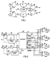
- a Dolby surround encoder includes L (left) input on line 10, R (right) input on line 12, C (center) inputs on lines 14, 16, and S (surround) input on line 18.
- the L input and a 0.707 C input are applied to summing circuit 20 and its output is applied on line 22 to phase compensation circuit 24 whose output is applied on line 26 to summing circuit 28 that produces A output on line 30.
- the R input on line 12 is similarly applied to summing circuit 32 and combined with a 0.707 C input for application on line 34 to phase compensation circuit 36 whose output on line 38 is applied to subtractor circuit 40 which has an output on line 42 as the B signal.
- the surround signal S on line 18 is applied to phase shift circuit 44 whose output on line 46 is supplied (x 0.707) to summing circuit 28 and subtractor circuit 40 to provide output signals A and B on lines 30, 42, respectively.
- the A and B signals are applied to the decoder system shown in Figure 2 on lines 50, 52, respectively.
- the A signal on line 50 is passed through variable delay circuit 54 and gain circuit 56 for application to input 58 of decoder 60
- the B signal on line 52 is passed through variable gain circuit 62 and delay circuit 64 for application to input 66 of decoder 60.
- Decoder 60 has an A output on line 70, an attenuated A a output on line 72, a B output on line 76, an attenuated B a output on line 78, an attenuated C a output on line 74, and an attenuated S a output on line 80.
- Those output signals are applied to a combining matrix that includes combining units 86, 88, 90 and 92, the output of combining units 86 being applied for line 94 to one or more output unit such as loud speaker 102L, the output of combining unit 88 being applied over line 96 to one or more output devices such as loud speaker 102R, the output of combining unit 90 being applied over line 98 to one or more output devices such as loud speaker 102C, and the output of combining unit 92 being applied over line 100 to one or more output devices such as loud speaker 102S.
- Decoder 60 Connected between lines 58 and 66 are balance compensation 104 whose outputs 106, 108 are connected to variable gain circuit 62 and azimuth compensation 110 whose outputs are applied over lines 112, 114 to variable delay 54. Decoder 60 has a dialog sensing output on line 116 to balance compensation 104 and a similar dialog sensing output on line 118 to azimuth compensation.
- decoder 60 Further details of decoder 60 may be seen with reference to Figure 3.
- the signal on line 58 Is applied through sixteen millisecond delay 120 to input 122 of combining component 86 whose output is applied on line 94.
- the output of delay 120 is also applied to attenuator 124 (which may be a voltage controlled amplifier in an analog embodiment or a digital multiplier in a digital embodiment) and its output is applied through 0.414 "boost" amplifier 126 to plus input 128 of combining component 86.
- the signal on line 58 is applied through gain control 130 to rectifier 132, to adder 134 and to the positive input of subtractor 136.
- the B input signal on line 66 is similarly applied through sixteen millisecond delay 140, gain control 142, adder 134, and to the negative input of subtractor 136.
- adder 134 applies the sum of the signals on lines 58 and 66 as a C (center) output signal to recitifier 146 and subtractor 136 applies the difference of those two signals as an S (surround) output to rectifier 148.
- each rectifier 132, 144, 146 and 148 Coupled to the output of each rectifier 132, 144, 146 and 148 is a log circuit 150, 152, 154, 156, respectively (which may be look-up tables in a digital embodiment)--the output of log circuit 150 on line 162 being the log of the value of the input signal A that is applied to the positive input of subtractor 164; the output of log circuit 152 on line 166 being the log of the input signal B which is applied to the negative input of subtractor 164; the output of log circuit 154 on line 168 being the log of the sum (C) of those two input signals which is applied to the positive input of subtractor 170; and the output of log circuit 156 on line 172 being the log of the difference (S) of those two input signals and applied to the negative input of subtractor 170.
- the output of log circuit 150 on line 162 being the log of the value of the input signal A that is applied to the positive input of subtractor 164
- each subtractor 164, 170 Connected to the output of each subtractor 164, 170 is a switched time constant arrangement 174 and 188, respectively, for selectively inserting a delay, (for example one hundred millisecond).
- the output of subtractor 164 is applied to function circuits 180 and 182 (which may be look-up tables in a digital embodiment) while the output of subtractor 170 is applied to function circuits 184, 186.
- the output of subtractor 164 (A - B) as modified by function circuit 180 is applied to attenuator 124 to provide a steering control (A a ) output on line 72; and through function circuit 182 to similarly control attenuation via attenuator 188 of the B input to provide a second steering control (B a ) output on line 78.
- the log difference signal (C - S) from subtractor 170 is applied through time constant network 188 to function circuits 184 and 186 to modify respectively the C signal applied to attenuator 190 and the S signal applied to attenuator 192, respectively.
- the steering control signals C a and S a on lines 74 and 80, respectively, are applied through 0.5 amplification stages 194, 196, respectively, to inputs 198, 199, respectively, of combining unit 86.
- Function circuits 180, 182, 184 and 186 are preferably implemented such that smooth steering and complete cancellation in outputs are obtained while preserving the energy of both the steered and unsteered signals.
- the system also includes automatic gain control (AGC) of the input signals.
- AGC automatic gain control
- analog peak detectors and rectifiers may be used which continuously follow the input signals while in a digital implementation, level signals may be read periodically and adjusted appropriately.
- threshold unit 200 in response to a strong centrally-steered signal output on line 116 (when the log difference of C - S is at least six dB) provides an output on line 202 to condition gate circuit 204. That log difference signal is also applied to multiplier 206 over line 208. A second input to multiplier 206 (on line 210) is the level difference between the A and B input signals as provided by subtractor 212. The output of multiplier 206 on line 214 is applied through gate 204 to integrator 216. Integrator 216 is tested periodically, and if its value is negative , a signal on line 108 is applied to gain control circiut 62 to reduce the gain. Similarly, if the integrator output is positive, a signal on line 106 is applied to gain control circuit 62 to increase the gain.
- a resulting output on line 118 is applied to corresponding gates 220, 222 to apply successive samples of the input A and B signals on lines 50 and 52, respectively, to four stage test delay units 224, 226, respectively.
- a sample of the B input on line 52 (delay stage 226-2) is compared with the immediately-following sample on line 50 (delay stage 224-1) by subtractor 228 whose output is applied to over line 230 to test circuit 232.
- the same B input sample from line 52 is supplied from delay stage 226-3 and subtracted from the immediately-preceding A input sample from delay stage 224-4 by subtractor 234 and applied over line 236 to test circuit 232.
- the resulting bias signal (if any) on line 238 is applied to integrator 240 and if there is a consistent bias, delay 54 is adjusted appropriately, a signal on line 112 increasing the delay and a signal on line 114 decreasing the delay.
- the system thus continually monitors level and phase and provides adjustment as necessary in response to strong dialog (centrally steered) inputs to provide balance and azimuth compensation and improved steering accordingly results.
- the system has good "balance” and low time delay "azimuth” between the incoming signals so that unwanted signals are accurately removed and clean steering is produced in the presence of ambience. If the input signals are accurately balanced and in phase, the system tends to place all the dialog in the center speaker 102G (shown in Figure 2), and dialog in the surround speaker 102S (shown in Figure 2) normally the difference between the left and right inputs, will be zero.
Landscapes
- Physics & Mathematics (AREA)
- Engineering & Computer Science (AREA)
- Acoustics & Sound (AREA)
- Signal Processing (AREA)
- Stereophonic System (AREA)
Claims (10)
- Système de renforcement de la directivité destiné à être utilisé dans la lecture d'un enregistrement vidéo et destiné à convertir des signaux stéréocodés sur des canaux d'entrée A et B en quatre signaux de canaux de sortie de gauche, du centre, de droite et d'ambiance, respectivement, comportant :caractérisé en ce que ledit moyen (190, 184) destiné à atténuer la somme desdits signaux d'entrée et ledit moyen (192, 186) destiné à atténuer la différence desdits signaux d'entrée atténuent chacun selon une fonction respective de la différence de logarithmes de la somme et de la différence desdits signaux d'entrée, et le système comprendun moyen (124, 180) destiné à atténuer le signal d'entrée sur le canal d'entrée A en fonction de la différence des logarithmes des signaux sur les canaux d'entrée A et B pour produire un premier signal atténué Aa,un moyen (188, 182) destiné à atténuer le signal d'entrée sur le canal d'entrée B en fonction de la différence des logarithmes des signaux sur les canaux d'entrée A et B pour produire un second signal atténué Ba,un moyen (190, 184) destiné à atténuer la somme des signaux d'entrée sur les canaux d'entrée A et B en fonction des signaux sur les canaux d'entrée A et B pour produire un troisième signal atténué Ca, etun moyen (192, 186) destiné à atténuer la différence des signaux sur les canaux d'entrée A et B en fonction des signaux sur les canaux d'entrée A et B pour produire un quatrième signal atténué Sa,
un moyen (86, 88, 90, 92) destiné à combiner le signal sur le canal d'entrée A, le signal sur le canal d'entrée B, la somme des signaux sur les canaux d'entrée A et B, la différence des signaux sur les canaux d'entrée A et B, et lesdits premier, deuxième, troisième et quatrième signaux atténués pour produire des signaux de sortie de gauche, du centre, de droite et d'ambiance ;
un moyen qui, en réponse à un signal fort, orienté centralement, est destiné à comparer le signal sur le canal d'entrée A avec un échantillon immédiatement précédent du signal sur le canal d'entrée B (228) pour produire un premier signal de référence (230), et à comparer un échantillon dudit signal sur le canal d'entrée A avec un échantillon immédiatement suivant du signal sur le canal d'entrée B (234) pour obtenir un second signal de référence (236),
un moyen (232) destiné à comparer lesdits premier et second signaux de référence, et
un moyen (54, 240) de commande de retard qui, en réponse audit moyen de comparaison, est destiné à ajuster le retard de l'un desdits canaux d'entrée en fonction de la différence entre lesdits signaux de référence pour produire une compensation d'azimut pour des signaux sur lesdits canaux d'entrée A et B, grâce à quoi des erreurs d'azimut sont corrigées à la lecture de l'enregistrement. - Système selon la revendication 1, dans lequel ledit moyen de combinaison comprend un premier moyen de combinaison (86) destiné à combiner ledit signal d'entrée sur ledit canal A avec un premier signal atténué modifié, un troisième signal atténué modifié et un quatrième signal atténué modifié pour produire ledit signal de sortie de gauche.
- Système selon la revendication 2, dans lequel ledit premier moyen de combinaison (86) comprend un moyen destiné à additionner ledit signal d'entrée sur ledit canal A et ledit premier signal atténué modifié, et à soustraire lesdits troisième et quatrième signaux atténués modifiés.
- Système selon l'une quelconque des revendications précédentes, dans lequel ledit moyen de combinaison comprend un second moyen de combinaison (88) destiné à combiner ledit signal d'entrée sur ledit canal B avec un deuxième signal atténué modifié, un troisième signal atténué modifié et un quatrième signal atténué modifié pour produire ledit signal de sortie de droite.
- Système selon la revendication 4, dans lequel ledit second moyen de combinaison (88) comprend un moyen destiné à additionner ledit signal d'entrée sur ledit canal B, ledit deuxième signal atténué modifié et ledit quatrième signal atténué modifié, et à soustraire ledit troisième signal modifié.
- Système selon l'une quelconque des revendications précédentes, dans lequel ledit moyen de combinaison comprend un troisième moyen de combinaison (90) destiné à combiner lesdits signaux d'entrée sur lesdits canaux A et B avec un troisième signal atténué modifié, ledit premier signal atténué et ledit deuxième signal atténué pour produire ledit signal de sortie du centre.
- Système selon la revendication 6, dans lequel ledit troisième moyen de combinaison comprend un moyen destiné à additionner lesdits signaux d'entrée sur lesdits canaux A et B et ledit troisième signal atténué modifié, et à soustraire lesdits premier et deuxième signaux atténués.
- Système selon l'une quelconque des revendications précédentes, dans lequel ledit moyen de combinaison comprend un quatrième moyen de combinaison (92) destiné à combiner lesdits signaux d'entrée sur lesdits canaux A et B un quatrième signal atténué modifié, ledit premier signal atténué et ledit deuxième signal atténué pour produire ledit signal de sortie d'ambiance.
- Système selon la revendication 8, dans lequel ledit quatrième moyen de combinaison comprend un moyen destiné à additionner ledit signal d'entrée sur ledit canal A, ledit deuxième signal atténué et ledit quatrième signal atténué modifié, et à soustraire ledit signal d'entrée sur ledit canal B et ledit premier signal atténué pour produire ledit signal de sortie d'ambiance.
- Système selon la revendication 1, dans lequel ledit moyen de combinaison comprend
un premier moyen de combinaison (86) qui comprend un moyen destiné à additionner ledit signal d'entrée (70) sur ledit canal A et ledit premier signal atténué (72) modifié par un facteur de (0,414) (126), et à soustraire lesdits troisième et quatrième signaux atténués modifiés (74, 80), chacun desdits troisième et quatrième signaux atténués modifiés étant modifié d'un facteur (0,5) (194, 196), pour produire ledit signal de sortie de gauche ;
un deuxième moyen de combinaison (88) qui comprend un moyen destiné à additionner ledit signal d'entrée (76) sur ledit canal B, ledit deuxième signal atténué (78) modifié par un facteur de (0,414) et un quatrième signal atténué modifié (80), et à soustraire un troisième signal modifié (74), chacun desdits troisième et quatrième signaux atténués modifiés étant modifié d'un facteur (0,5) (194, 196), pour produire ledit signal de sortie de droite ;
un troisième moyen de combinaison (90) qui comprend un moyen destiné à additionner lesdits signaux d'entrée (70, 76) sur lesdits canaux A et B et ledit troisième signal atténué (74) modifié par un facteur de (0,414), et à soustraire lesdits premier et deuxième signaux modifiés (72, 78) pour produire ledit signal de sortie du centre ;
un quatrième moyen de combinaison (92) qui comprend un moyen destiné à additionner ledit signal d'entrée (70) sur ledit canal A, ledit deuxième signal atténué (78) et ledit quatrième signal atténué modifié (80) modifié par un facteur de (0,414), et à soustraire ledit signal d'entrée (76) sur ledit canal B et ledit premier signal atténué (72) pour produire ledit signal de sortie d'ambiance.
Applications Claiming Priority (3)
| Application Number | Priority Date | Filing Date | Title |
|---|---|---|---|
| US07/141,212 US4862502A (en) | 1988-01-06 | 1988-01-06 | Sound reproduction |
| US141212 | 1988-01-06 | ||
| EP89300070A EP0323904B1 (fr) | 1988-01-06 | 1989-01-05 | Reproduction sonore |
Related Parent Applications (1)
| Application Number | Title | Priority Date | Filing Date |
|---|---|---|---|
| EP89300070A Division EP0323904B1 (fr) | 1988-01-06 | 1989-01-05 | Reproduction sonore |
Publications (3)
| Publication Number | Publication Date |
|---|---|
| EP0820213A2 EP0820213A2 (fr) | 1998-01-21 |
| EP0820213A3 EP0820213A3 (fr) | 1998-03-11 |
| EP0820213B1 true EP0820213B1 (fr) | 2003-10-22 |
Family
ID=22494682
Family Applications (2)
| Application Number | Title | Priority Date | Filing Date |
|---|---|---|---|
| EP89300070A Expired - Lifetime EP0323904B1 (fr) | 1988-01-06 | 1989-01-05 | Reproduction sonore |
| EP97203117A Expired - Lifetime EP0820213B1 (fr) | 1988-01-06 | 1989-01-05 | Système de reproduction de son |
Family Applications Before (1)
| Application Number | Title | Priority Date | Filing Date |
|---|---|---|---|
| EP89300070A Expired - Lifetime EP0323904B1 (fr) | 1988-01-06 | 1989-01-05 | Reproduction sonore |
Country Status (4)
| Country | Link |
|---|---|
| US (1) | US4862502A (fr) |
| EP (2) | EP0323904B1 (fr) |
| JP (1) | JP2695888B2 (fr) |
| DE (2) | DE68928653T2 (fr) |
Families Citing this family (33)
| Publication number | Priority date | Publication date | Assignee | Title |
|---|---|---|---|---|
| JPS63183495A (ja) * | 1987-01-27 | 1988-07-28 | ヤマハ株式会社 | 音場制御装置 |
| JPH0623119Y2 (ja) * | 1989-01-24 | 1994-06-15 | パイオニア株式会社 | サラウンド方式ステレオ再生装置 |
| JP2589199B2 (ja) * | 1990-04-26 | 1997-03-12 | 三洋電機株式会社 | デジタルデータの非線形変換方法及びこれを用いた信号処理装置 |
| JPH0410009A (ja) * | 1990-04-26 | 1992-01-14 | Sanyo Electric Co Ltd | デジタルデータの非線形変換方法及びこれを用いた信号処理装置 |
| US5136650A (en) * | 1991-01-09 | 1992-08-04 | Lexicon, Inc. | Sound reproduction |
| US6118876A (en) * | 1995-09-07 | 2000-09-12 | Rep Investment Limited Liability Company | Surround sound speaker system for improved spatial effects |
| US5708719A (en) * | 1995-09-07 | 1998-01-13 | Rep Investment Limited Liability Company | In-home theater surround sound speaker system |
| US5930370A (en) * | 1995-09-07 | 1999-07-27 | Rep Investment Limited Liability | In-home theater surround sound speaker system |
| US5642423A (en) * | 1995-11-22 | 1997-06-24 | Sony Corporation | Digital surround sound processor |
| US6697491B1 (en) * | 1996-07-19 | 2004-02-24 | Harman International Industries, Incorporated | 5-2-5 matrix encoder and decoder system |
| US5796844A (en) * | 1996-07-19 | 1998-08-18 | Lexicon | Multichannel active matrix sound reproduction with maximum lateral separation |
| US5870480A (en) * | 1996-07-19 | 1999-02-09 | Lexicon | Multichannel active matrix encoder and decoder with maximum lateral separation |
| US5912976A (en) | 1996-11-07 | 1999-06-15 | Srs Labs, Inc. | Multi-channel audio enhancement system for use in recording and playback and methods for providing same |
| EP1013140B1 (fr) * | 1997-09-05 | 2012-12-05 | Harman International Industries, Incorporated | Systeme de decodage a matrice 5-2-5 |
| JP4151110B2 (ja) * | 1998-05-14 | 2008-09-17 | ソニー株式会社 | オーディオ信号処理装置およびオーディオ信号再生装置 |
| WO2002007481A2 (fr) | 2000-07-19 | 2002-01-24 | Koninklijke Philips Electronics N.V. | Convertisseur stereo multicanaux de derivation d'un signal centrale stereo d'ambiophonie et/ou audio |
| US7451006B2 (en) * | 2001-05-07 | 2008-11-11 | Harman International Industries, Incorporated | Sound processing system using distortion limiting techniques |
| US7447321B2 (en) | 2001-05-07 | 2008-11-04 | Harman International Industries, Incorporated | Sound processing system for configuration of audio signals in a vehicle |
| US6804565B2 (en) * | 2001-05-07 | 2004-10-12 | Harman International Industries, Incorporated | Data-driven software architecture for digital sound processing and equalization |
| KR100548899B1 (ko) * | 2001-05-11 | 2006-02-02 | 교세라 가부시키가이샤 | 휴대용 통신 단말기, 무선 데이터 통신 네트워크 시스템, 무선 통신 장치와 그 방법, 및 통신 방식 전환 방법 |
| US7443987B2 (en) * | 2002-05-03 | 2008-10-28 | Harman International Industries, Incorporated | Discrete surround audio system for home and automotive listening |
| EP1502361B1 (fr) * | 2002-05-03 | 2015-01-14 | Harman International Industries Incorporated | Melangeur abaisseur multicanal |
| CA2773294C (fr) * | 2002-05-03 | 2013-03-12 | Harman International Industries, Incorporated | Systeme de detection et de localisation sonore |
| US7542815B1 (en) * | 2003-09-04 | 2009-06-02 | Akita Blue, Inc. | Extraction of left/center/right information from two-channel stereo sources |
| SG124306A1 (en) * | 2005-01-20 | 2006-08-30 | St Microelectronics Asia | A system and method for expanding multi-speaker playback |
| US8050434B1 (en) | 2006-12-21 | 2011-11-01 | Srs Labs, Inc. | Multi-channel audio enhancement system |
| JP5955862B2 (ja) | 2011-01-04 | 2016-07-20 | ディーティーエス・エルエルシーDts Llc | 没入型オーディオ・レンダリング・システム |
| WO2014144968A1 (fr) | 2013-03-15 | 2014-09-18 | O'polka Richard | Système sonore portable |
| US10149058B2 (en) | 2013-03-15 | 2018-12-04 | Richard O'Polka | Portable sound system |
| USD740784S1 (en) | 2014-03-14 | 2015-10-13 | Richard O'Polka | Portable sound device |
| MC200185B1 (fr) | 2016-09-16 | 2017-10-04 | Coronal Audio | Dispositif et procédé de captation et traitement d'un champ acoustique tridimensionnel |
| MC200186B1 (fr) | 2016-09-30 | 2017-10-18 | Coronal Encoding | Procédé de conversion, d'encodage stéréophonique, de décodage et de transcodage d'un signal audio tridimensionnel |
| US10983791B2 (en) * | 2018-08-29 | 2021-04-20 | Aktiebolaget Skf | Processor-implemented system and method for vector analysis to extract a speed of a rotating part of a machine where there is no trigger signal present |
Family Cites Families (18)
| Publication number | Priority date | Publication date | Assignee | Title |
|---|---|---|---|---|
| GB1112233A (en) * | 1965-05-10 | 1968-05-01 | Deutsche Post Inst | Electro-acoustic system for stereophonic reproduction |
| US3959590A (en) * | 1969-01-11 | 1976-05-25 | Peter Scheiber | Stereophonic sound system |
| US3812295A (en) * | 1970-10-19 | 1974-05-21 | Columbia Broadcasting Syst Inc | Quadraphonic reproducing system with gain riding logic |
| US3798373A (en) * | 1971-06-23 | 1974-03-19 | Columbia Broadcasting Syst Inc | Apparatus for reproducing quadraphonic sound |
| JPS5213082B1 (fr) * | 1971-07-19 | 1977-04-12 | ||
| US3772479A (en) * | 1971-10-19 | 1973-11-13 | Motorola Inc | Gain modified multi-channel audio system |
| GB1402320A (en) * | 1971-10-25 | 1975-08-06 | Sansui Electric Co | Decoder for use in 4-2-4 matrix playback system |
| JPS5235282B2 (fr) * | 1972-09-09 | 1977-09-08 | ||
| US3829615A (en) * | 1972-10-04 | 1974-08-13 | Mitsubishi Electric Corp | Quaternary stereophonic sound reproduction apparatus |
| JPS5317283B2 (fr) * | 1973-03-07 | 1978-06-07 | ||
| JPS5248001B2 (fr) * | 1973-08-20 | 1977-12-07 | ||
| GB1514162A (en) * | 1974-03-25 | 1978-06-14 | Ruggles W | Directional enhancement system for quadraphonic decoders |
| US3943287A (en) * | 1974-06-03 | 1976-03-09 | Cbs Inc. | Apparatus and method for decoding four channel sound |
| GB1522135A (en) * | 1974-08-29 | 1978-08-23 | Dolby Laboratories Inc | Stereophonic sound system |
| US4027101A (en) * | 1976-04-26 | 1977-05-31 | Hybrid Systems Corporation | Simulation of reverberation in audio signals |
| US4236039A (en) * | 1976-07-19 | 1980-11-25 | National Research Development Corporation | Signal matrixing for directional reproduction of sound |
| GB2067057B (en) * | 1979-12-19 | 1984-04-18 | Indep Broadcasting Authority | Sound system |
| US4704728A (en) * | 1984-12-31 | 1987-11-03 | Peter Scheiber | Signal re-distribution, decoding and processing in accordance with amplitude, phase, and other characteristics |
-
1988
- 1988-01-06 US US07/141,212 patent/US4862502A/en not_active Expired - Lifetime
-
1989
- 1989-01-05 EP EP89300070A patent/EP0323904B1/fr not_active Expired - Lifetime
- 1989-01-05 EP EP97203117A patent/EP0820213B1/fr not_active Expired - Lifetime
- 1989-01-05 DE DE68928653T patent/DE68928653T2/de not_active Expired - Lifetime
- 1989-01-05 DE DE68929498T patent/DE68929498T2/de not_active Expired - Lifetime
- 1989-01-06 JP JP64001135A patent/JP2695888B2/ja not_active Expired - Lifetime
Also Published As
| Publication number | Publication date |
|---|---|
| JP2695888B2 (ja) | 1998-01-14 |
| JPH0270200A (ja) | 1990-03-09 |
| DE68929498T2 (de) | 2004-08-12 |
| EP0323904A3 (fr) | 1991-10-23 |
| EP0820213A2 (fr) | 1998-01-21 |
| EP0323904B1 (fr) | 1998-04-29 |
| EP0820213A3 (fr) | 1998-03-11 |
| US4862502A (en) | 1989-08-29 |
| DE68928653T2 (de) | 1998-11-26 |
| DE68929498D1 (de) | 2003-11-27 |
| DE68928653D1 (de) | 1998-06-04 |
| EP0323904A2 (fr) | 1989-07-12 |
Similar Documents
| Publication | Publication Date | Title |
|---|---|---|
| EP0820213B1 (fr) | Système de reproduction de son | |
| US5136650A (en) | Sound reproduction | |
| JP4354017B2 (ja) | 5−2−5マトリクス・システム | |
| EP0923848B1 (fr) | Reproduction sonore a matrice active multicanaux avec separation laterale maximale | |
| US5870480A (en) | Multichannel active matrix encoder and decoder with maximum lateral separation | |
| US4799260A (en) | Variable matrix decoder | |
| US6650755B2 (en) | Voice-to-remaining audio (VRA) interactive center channel downmix | |
| US4024344A (en) | Center channel derivation for stereophonic cinema sound | |
| US6498852B2 (en) | Automatic LFE audio signal derivation system | |
| US5818941A (en) | Configurable cinema sound system | |
| US5727068A (en) | Matrix decoding method and apparatus | |
| AU750877C (en) | 5-2-5 matrix encoder and decoder system | |
| US6198827B1 (en) | 5-2-5 Matrix system | |
| JPH05219600A (ja) | ステレオ強調および指向性サーボを備えたオージオサラウンドシステム | |
| US6850622B2 (en) | Sound field correction circuit | |
| AU2012267193B2 (en) | Matrix encoder with improved channel separation | |
| US20040096065A1 (en) | Voice-to-remaining audio (VRA) interactive center channel downmix | |
| JP3284747B2 (ja) | 音場制御装置 | |
| EP0630168B1 (fr) | Décodeur prologic Dolby | |
| JPH05268700A (ja) | ステレオ聴覚補助装置 | |
| AU2015275309A1 (en) | Matrix encoder with improved channel separation | |
| KR19990049276A (ko) | 디지털 오디오 시스템의 오디오 밸런스 조정 장치 |
Legal Events
| Date | Code | Title | Description |
|---|---|---|---|
| PUAI | Public reference made under article 153(3) epc to a published international application that has entered the european phase |
Free format text: ORIGINAL CODE: 0009012 |
|
| 17P | Request for examination filed |
Effective date: 19971007 |
|
| AC | Divisional application: reference to earlier application |
Ref document number: 323904 Country of ref document: EP |
|
| AK | Designated contracting states |
Kind code of ref document: A2 Designated state(s): DE FR GB IT NL |
|
| PUAL | Search report despatched |
Free format text: ORIGINAL CODE: 0009013 |
|
| AK | Designated contracting states |
Kind code of ref document: A3 Designated state(s): DE FR GB IT NL |
|
| GRAH | Despatch of communication of intention to grant a patent |
Free format text: ORIGINAL CODE: EPIDOS IGRA |
|
| GRAS | Grant fee paid |
Free format text: ORIGINAL CODE: EPIDOSNIGR3 |
|
| GRAA | (expected) grant |
Free format text: ORIGINAL CODE: 0009210 |
|
| AC | Divisional application: reference to earlier application |
Ref document number: 0323904 Country of ref document: EP Kind code of ref document: P |
|
| AK | Designated contracting states |
Kind code of ref document: B1 Designated state(s): DE FR GB IT NL |
|
| PG25 | Lapsed in a contracting state [announced via postgrant information from national office to epo] |
Ref country code: NL Free format text: LAPSE BECAUSE OF FAILURE TO SUBMIT A TRANSLATION OF THE DESCRIPTION OR TO PAY THE FEE WITHIN THE PRESCRIBED TIME-LIMIT Effective date: 20031022 Ref country code: IT Free format text: LAPSE BECAUSE OF FAILURE TO SUBMIT A TRANSLATION OF THE DESCRIPTION OR TO PAY THE FEE WITHIN THE PRESCRIBED TIME-LIMIT;WARNING: LAPSES OF ITALIAN PATENTS WITH EFFECTIVE DATE BEFORE 2007 MAY HAVE OCCURRED AT ANY TIME BEFORE 2007. THE CORRECT EFFECTIVE DATE MAY BE DIFFERENT FROM THE ONE RECORDED. Effective date: 20031022 |
|
| REG | Reference to a national code |
Ref country code: GB Ref legal event code: FG4D |
|
| REF | Corresponds to: |
Ref document number: 68929498 Country of ref document: DE Date of ref document: 20031127 Kind code of ref document: P |
|
| PGFP | Annual fee paid to national office [announced via postgrant information from national office to epo] |
Ref country code: NL Payment date: 20031216 Year of fee payment: 16 |
|
| NLV1 | Nl: lapsed or annulled due to failure to fulfill the requirements of art. 29p and 29m of the patents act | ||
| ET | Fr: translation filed | ||
| PLBE | No opposition filed within time limit |
Free format text: ORIGINAL CODE: 0009261 |
|
| STAA | Information on the status of an ep patent application or granted ep patent |
Free format text: STATUS: NO OPPOSITION FILED WITHIN TIME LIMIT |
|
| 26N | No opposition filed |
Effective date: 20040723 |
|
| PGFP | Annual fee paid to national office [announced via postgrant information from national office to epo] |
Ref country code: GB Payment date: 20080129 Year of fee payment: 20 |
|
| PGFP | Annual fee paid to national office [announced via postgrant information from national office to epo] |
Ref country code: FR Payment date: 20080130 Year of fee payment: 20 Ref country code: DE Payment date: 20080229 Year of fee payment: 20 |
|
| REG | Reference to a national code |
Ref country code: GB Ref legal event code: PE20 Expiry date: 20090104 |
|
| PG25 | Lapsed in a contracting state [announced via postgrant information from national office to epo] |
Ref country code: GB Free format text: LAPSE BECAUSE OF EXPIRATION OF PROTECTION Effective date: 20090104 |