EP0820367B1 - Modulares lager -und transpoersystem für werkzeuge und materialen - Google Patents
Modulares lager -und transpoersystem für werkzeuge und materialen Download PDFInfo
- Publication number
- EP0820367B1 EP0820367B1 EP97902737A EP97902737A EP0820367B1 EP 0820367 B1 EP0820367 B1 EP 0820367B1 EP 97902737 A EP97902737 A EP 97902737A EP 97902737 A EP97902737 A EP 97902737A EP 0820367 B1 EP0820367 B1 EP 0820367B1
- Authority
- EP
- European Patent Office
- Prior art keywords
- module
- pivot
- pivot shaft
- tools
- modules
- Prior art date
- Legal status (The legal status is an assumption and is not a legal conclusion. Google has not performed a legal analysis and makes no representation as to the accuracy of the status listed.)
- Expired - Lifetime
Links
- 239000000463 material Substances 0.000 title claims description 14
- 230000008878 coupling Effects 0.000 claims abstract description 14
- 238000010168 coupling process Methods 0.000 claims abstract description 14
- 238000005859 coupling reaction Methods 0.000 claims abstract description 14
- 235000004443 Ricinus communis Nutrition 0.000 claims description 6
- 240000000528 Ricinus communis Species 0.000 claims description 5
- 239000004033 plastic Substances 0.000 claims description 3
- 230000002093 peripheral effect Effects 0.000 claims 3
- 230000005540 biological transmission Effects 0.000 claims 1
- 238000001746 injection moulding Methods 0.000 claims 1
- 230000000295 complement effect Effects 0.000 description 2
- 230000007613 environmental effect Effects 0.000 description 1
- 239000003000 extruded plastic Substances 0.000 description 1
- 239000002184 metal Substances 0.000 description 1
- 238000004806 packaging method and process Methods 0.000 description 1
Images


Classifications
-
- B—PERFORMING OPERATIONS; TRANSPORTING
- B65—CONVEYING; PACKING; STORING; HANDLING THIN OR FILAMENTARY MATERIAL
- B65D—CONTAINERS FOR STORAGE OR TRANSPORT OF ARTICLES OR MATERIALS, e.g. BAGS, BARRELS, BOTTLES, BOXES, CANS, CARTONS, CRATES, DRUMS, JARS, TANKS, HOPPERS, FORWARDING CONTAINERS; ACCESSORIES, CLOSURES, OR FITTINGS THEREFOR; PACKAGING ELEMENTS; PACKAGES
- B65D21/00—Nestable, stackable or joinable containers; Containers of variable capacity
- B65D21/08—Containers of variable capacity
- B65D21/083—Containers of variable capacity by means of additional elements, e.g. modular
-
- B—PERFORMING OPERATIONS; TRANSPORTING
- B25—HAND TOOLS; PORTABLE POWER-DRIVEN TOOLS; MANIPULATORS
- B25H—WORKSHOP EQUIPMENT, e.g. FOR MARKING-OUT WORK; STORAGE MEANS FOR WORKSHOPS
- B25H3/00—Storage means or arrangements for workshops facilitating access to, or handling of, work tools or instruments
- B25H3/02—Boxes
- B25H3/021—Boxes comprising a number of connected storage elements
- B25H3/023—Boxes comprising a number of connected storage elements movable relative to one another for access to their interiors
-
- B—PERFORMING OPERATIONS; TRANSPORTING
- B25—HAND TOOLS; PORTABLE POWER-DRIVEN TOOLS; MANIPULATORS
- B25H—WORKSHOP EQUIPMENT, e.g. FOR MARKING-OUT WORK; STORAGE MEANS FOR WORKSHOPS
- B25H3/00—Storage means or arrangements for workshops facilitating access to, or handling of, work tools or instruments
- B25H3/02—Boxes
- B25H3/021—Boxes comprising a number of connected storage elements
- B25H3/023—Boxes comprising a number of connected storage elements movable relative to one another for access to their interiors
- B25H3/025—Boxes comprising a number of connected storage elements movable relative to one another for access to their interiors by rotation about a common axis
-
- E—FIXED CONSTRUCTIONS
- E05—LOCKS; KEYS; WINDOW OR DOOR FITTINGS; SAFES
- E05D—HINGES OR SUSPENSION DEVICES FOR DOORS, WINDOWS OR WINGS
- E05D7/00—Hinges or pivots of special construction
- E05D7/10—Hinges or pivots of special construction to allow easy separation or connection of the parts at the hinge axis
- E05D7/1061—Hinges or pivots of special construction to allow easy separation or connection of the parts at the hinge axis in a radial direction
- E05D7/1077—Hinges or pivots of special construction to allow easy separation or connection of the parts at the hinge axis in a radial direction with snap-fitted pins
-
- E—FIXED CONSTRUCTIONS
- E05—LOCKS; KEYS; WINDOW OR DOOR FITTINGS; SAFES
- E05Y—INDEXING SCHEME ASSOCIATED WITH SUBCLASSES E05D AND E05F, RELATING TO CONSTRUCTION ELEMENTS, ELECTRIC CONTROL, POWER SUPPLY, POWER SIGNAL OR TRANSMISSION, USER INTERFACES, MOUNTING OR COUPLING, DETAILS, ACCESSORIES, AUXILIARY OPERATIONS NOT OTHERWISE PROVIDED FOR, APPLICATION THEREOF
- E05Y2999/00—Subject-matter not otherwise provided for in this subclass
Definitions
- the invention concerns a device for storage and transport of tools and materials, consisting of modules, as described in the pre-characterizing part of Claim 1.
- a device for storage and transport of tools and materials, consisting of modules, as described in the pre-characterizing part of Claim 1.
- Such a device is known from the document EP-A-566983.
- Many other systems for storage and transport of tools are known.
- There are metal toolboxes that can be characterised by a limited overview of the content and a high weight.
- plastic toolboxes with a division in compartments and trays that characteristically have a limited overview and a limited capacity.
- toolboxes in which the tools are not stored in trays, but are fixed onto boards in an organised way, often by means of sleeve pockets, clamps or straps.
- Coupling and uncoupling of the modules is done by using a separate pivot pin having a relatively small diameter and a length substantially equal to the length of a module and passing through a number of pivot casings, so that one cannot speak of an easy (un)coupling of the modules.
- a unit, composed of modules, is meant to be used laying flat. If the modules on top contain heavy tools or materials, this leads to backward topping over of the unit. In addition, these heavy modules must be lifted every time the content of the modules underneath must be reached.
- US-A-5217115 discloses a reusable tool packaging system of complementary plastic planar members snapfit together and interlocked therebetween to allow a planar assembly or a configuration akin to a toolbox.
- complementary extruded plastic planar members can be used for hanging the planar assembly with one side, forming the outer side of the system in the toolbox configuration, flat on a wall.
- WO-A-90/08631 discloses a portable carrier for hand tools having an open frame member with two cover parts. Pivotally attached between the open frame member and a cover part is a plane on which tools or materials can be fixed on both sides.
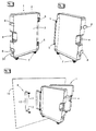
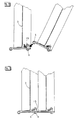
- the invention is aimed at providing a system for storage and transportation of tools and materials that is compact, well-organised and accessible under all circumstances, and the capacity of which can easily be adapted. According to the invention, this is achieved by the features of the characterizing part of claim 1 resulting in the possibility to couple modules in such a way that they can pivot with respect to each other, while on the other hand they can be hung on the wall separately, whereas each module has a plane on which tools or materials can be fixed from both sides. According to one preferred embodiment of the coupling means, described in Claim 2, coupling of the modules can be done in a user-friendly manner, so that it is possible to assemble a compact mobile unit, containing the right tools for a certain job, easily and quickly.
- each module may be equipped with small castors or elements of comparable function, so that when a number of modules is assembled to form a unit, the unit is moveable as a cart.
- the castor wheels allow easy movement of the modules with respect to each other, so that each module is easily accessible from both sides.
- a unit, consisting of one or more modules, can be closed by means of covers to protect the content from environmental influences and from damage.
- Each module can be equipped with a handle in such a way, that an assembled unit can be carried with one hand.
- the user can disassemble the unit at home or in the workshop easily, and hang the modules on the wall separately besides each other.
- a large number of tools can be stored on a relatively small wall surface, maintaining overview and accessibility.
- the tools can be fixed to the plane of the modules by means of suitable clamps or, more specifically, by means of a clamping system that holds each tool between two concave shoes or holders while clamping it axially through spring action.
- the tool holders are fixed to the perforated plane 3 by means of snap fingers.
- Figure 9 shows the top holder 17
- Figure 10 shows the lower holder 18.
- the top holder consits of a concave shoe 22 that is connected through a straight guidance to a guiding block 19 by means of calliper 23.
- the guiding block 19 is fixed to the perforated surface 3 by means of two snap fingers 20 and 21.
- the guiding block 19 can be moved up and down with respect to calliper 23.
- Two springs 24 deliver the spring force for the system.
- the lower holder 18 consists of a shoe 30, comparable to 22 to the extent that this shoe 30 is bevelled at the front side. In the shoe 30, two shafts 28 and 29 are mounted, that take care of a straight guidance in guiding block 25.
- the guiding block 25 can be fixed to plane 3 by means of snap fingers 26 and 27.
- the lower holder 18 has no springs, but is adjustable in height by means of adjusting bolt 31, so that the above described clamping of the tools can also be applied otherwise.
Landscapes
- Engineering & Computer Science (AREA)
- Mechanical Engineering (AREA)
- Purses, Travelling Bags, Baskets, Or Suitcases (AREA)
- Refuse Collection And Transfer (AREA)
- Load-Engaging Elements For Cranes (AREA)
- Manipulator (AREA)
- Earth Drilling (AREA)
- Nozzles (AREA)
- Workshop Equipment, Work Benches, Supports, Or Storage Means (AREA)
Claims (16)
- Vorrichtung zum Lagern und Transportieren von Werkzeugen und Materialien, wobei die Vorrichtung mindestens ein Modul (1) umfasst, welches an ein benachbartes Modul (1) gekuppelt werden kann und welches Kupplungsmittel (5, 6) umfasst, die gestatten, dass eine Vielzahl der Module in beliebiger Folge gekuppelt werden, so dass in einer gekuppelten Position sich jedes von der Vielzahl der Module in Bezug auf ein benachbartes Modul drehen kann, dadurch gekennzeichnet, dass jedes Modul eine Ebene (8) aufweist, auf der Werkzeuge oder Materialien auf beiden Seiten davon befestigt werden können, und ein offenes Rahmenglied (2) aufweist, welches die Ebene umgibt und stützt und eine Verstelfungsstruktur aufweist, welche die Kupplungsmittel (5, 6) umfasst, die zusätzlich jedes Modul getrennt von anderen Modulen in einer hängenden Position befestigt an einer Wand (10) stützen kann, in der das getrennte Modul an einen an der Wand montierten Halter (9) gekuppelt ist, so dass sich das getrennte Modul um eine vertikale Achse in Bezug auf den an der Wand montierten Halter drehen kann.
- Vorrichtung nach Anspruch 1, dadurch gekennzeichnet, dass die Kupplungsmittel einen Satz von Drehgelenkbolzenmitteln (5) mit einer ersten Drehachse umfassen und einen Satz von Drehgelenkgehäusemitteln (6) mit einer zweiten Drehachse, die sich In einem Abstand und parallel zu der ersten Drehachse erstreckt, wobei in der gekuppelten Position der Satz von Drehgelenkbolzenmitteln oder der Satz von Drehgelenkgehäusemitteln eines Moduls (1) mit dem Satz von Drehgelenkgehäusemitteln oder dem Satz von Drehgelenkbolzenmitteln eines benachbarten Moduls (1) und in der hängenden Position einer der Sätze mit dem an der Wand montierten Halter (9) gekuppelt ist.
- Vorrichtung nach Anspruch 2, dadurch gekennzeichnet, dass in der hängenden Position der Satz von Drehgelenkbolzenmitteln (6) zum Kuppein des Moduls an den an der Wand montierten Halter (9) verwendet wird.
- Vorrichtung nach Anspruch 2 oder 3, dadurch gekennzeichnet, dass der Satz von Drehgelenkgehäusemitteln (6) mindestens ein Drehgelenkbolzenlagergehäuse mit einer seitlichen Öffnung zum Einsetzen eines Drehgelenkbolzens des Satzes von Drehgelenkbolzenmitteln (5) umfasst, und einen Nocken (15), der aus einer Drehgelenkbolzeneinsetzposition zu einer Drehgelenkbolzenverriegelungsposition gedreht werden kann.
- , Vorrichtung nach Anspruch 4, dadurch gekennzeichnet, dass der Nocken (15) in der Richtung der Drehgelenkbolzenverriegelungsposition federbelastet ist.
- Vorrichtung nach einem der Ansprüche 2 bis 5, dadurch gekennzeichnet, dass das offene Rahmenglied (2) eine im wesentlichen rechtwinklige Konfiguration aufweist, wobei der Satz von Drehgelenkbolzenmitteln (5) festmachbar entlang der peripheren Kante von einer der Seiten des Rahmenglieds und der Satz von Drehgelenkgehäusemitteln (6) an der gegenüberliegenden peripheren Kante der Seite des Rahmenglieds angebracht ist.
- Vorrichtung nach Anspruch 6, dadurch gekennzeichnet, dass in der drehbar geschlossenen Position die offenen Rahmenglieder (2) eine geschlossene periphere Wand bilden.
- Vorrichtung nach Anspruch 6 oder 7, dadurch gekennzeichnet, dass eine Seite des Rahmengliedes (2), die senkrecht zu der Seite ist, welche die Kupplungsmittel (5, 6) trägt, mit Laufrollen oder Vorrichtungen mit einer vergleichbaren Funktion versehen ist.
- Vorrichtung nach einem der vorhergehenden Ansprüche, dadurch gekennzeichnet, dass lösbare Verschlüsse (8) vorhanden sind, um das Drehen der Module (1) in Bezug aufeinander in der gekuppelten und drehbar geschlossenen Position zu blockieren.
- Vorrichtung nach einem der Ansprüche 4 bis 9, dadurch gekennzeichnet, dass die Auskupplung von gekuppelten Modulen durch Drehen des Nockens (15) aus der Drehgelenkbolzenverriegelungsposition zu der Drehgelenkbolzeneinsetzposition durch einen einhändig betätigten Übertragungsmechanismus erreicht wird.
- Vorrichtung nach einem der vorhergehenden Ansprüche, dadurch gekennzeichnet, dass jedes Modul mit Mitteln zum Anbringen eines Tragegurtes oder Schultergurtes versehen ist.
- Vorrichtung nach einem der vorhergehenden Ansprüche, dadurch gekennzeichnet, dass die vorstehend erwähnte Ebene (3) mit einer großen Anzahl von Löchern in einem regelmäßigen Muster versehen ist, in denen Klemmen oder Halter für Werkzeuge oder Materialien befestigt werden können.
- Vorrichtung nach einem der vorhergehenden Ansprüche, dadurch gekennzeichnet, dass die vorstehend erwähnten Klemmen oder Halter in den entsprechenden Löchern von Ebene (3) mittels Schnappfingern, die an diesen Klemmen oder Haltern montiert sind oder Bestandteil dieser Klemmen oder Halter sind, befestigt werden können.
- Vorrichtung nach einem der vorhergehenden Ansprüche, dadurch gekennzeichnet, dass die Module aus Kunststoff mittels eines Spritzgießverfahrens hergestellt werden.
- Vorrichtung nach einem der vorhergehenden Ansprüche, dadurch gekennzeichnet, dass die Werkzeuge oder die Materiallen, die darin gelagert werden, mittels Klemmvorrichtungen befestigt werden können, die jeweils zwei Halter (17) und (18) umfassen, zwischen denen das Werkzeug oder Material durch eine axiale Klemmung zwischen den konkaven Schuhen (22) und (23), die sich, federbelastet oder nicht, axial in Bezug aufeinander bewegen können, geklemmt wird.
- Vorrichtung nach einem der vorhergehenden Ansprüche, dadurch gekennzeichnet, dass die vorstehend beschriebenen Klemmvorrichtungen für Werkzeuge oder Materialien so hergestellt sind, dass ein konkaver Schuh (22) beweglich gegen Federwirkung ist und der andere konkave Schuh (3) nicht federbelastet ist, und in Bezug auf den anderen konkaven Schuh (22) mittels einer oder mehrerer Stellschrauben befestigt werden kann,
Applications Claiming Priority (3)
| Application Number | Priority Date | Filing Date | Title |
|---|---|---|---|
| NL1002290A NL1002290C2 (nl) | 1996-02-09 | 1996-02-09 | Modulair opberg- en transport-systeem voor gereedschap en materiaal. |
| NL1002290 | 1996-02-09 | ||
| PCT/NL1997/000048 WO1997028931A1 (en) | 1996-02-09 | 1997-02-10 | Modular storage and transportation system of tools and materials |
Publications (2)
| Publication Number | Publication Date |
|---|---|
| EP0820367A1 EP0820367A1 (de) | 1998-01-28 |
| EP0820367B1 true EP0820367B1 (de) | 2004-08-18 |
Family
ID=19762274
Family Applications (1)
| Application Number | Title | Priority Date | Filing Date |
|---|---|---|---|
| EP97902737A Expired - Lifetime EP0820367B1 (de) | 1996-02-09 | 1997-02-10 | Modulares lager -und transpoersystem für werkzeuge und materialen |
Country Status (8)
| Country | Link |
|---|---|
| US (1) | US5984441A (de) |
| EP (1) | EP0820367B1 (de) |
| AT (1) | ATE273772T1 (de) |
| AU (1) | AU1675497A (de) |
| DE (1) | DE69730279T2 (de) |
| ES (1) | ES2227668T3 (de) |
| NL (1) | NL1002290C2 (de) |
| WO (1) | WO1997028931A1 (de) |
Families Citing this family (49)
| Publication number | Priority date | Publication date | Assignee | Title |
|---|---|---|---|---|
| US6213313B1 (en) * | 1998-06-12 | 2001-04-10 | Raymond H. Levy | Paint chip display system |
| US6272779B1 (en) | 1998-10-30 | 2001-08-14 | Steelcase Development Inc. | Display board system |
| US6463701B1 (en) | 1998-10-30 | 2002-10-15 | Steelcase Development Corporation | Work environment |
| US6540094B1 (en) * | 1998-10-30 | 2003-04-01 | Steelcase Development Corporation | Information display system |
| US6374547B1 (en) | 1998-10-30 | 2002-04-23 | Steelcase Development Inc. | Workstation |
| US6931795B1 (en) | 1998-10-30 | 2005-08-23 | Steelcase Development Corporation | Utility distribution system |
| US6647652B1 (en) | 1998-10-30 | 2003-11-18 | Steelcase Development Inc. | Display board system |
| US6971197B1 (en) | 1998-10-30 | 2005-12-06 | Steelcase Development Corporation | Display board system |
| US6892650B2 (en) * | 2001-06-22 | 2005-05-17 | Steelcase Development Corporation | Movable display support system |
| US6279761B1 (en) | 1999-03-01 | 2001-08-28 | Steelcase Development Inc. | Information display system |
| IL129040A0 (en) * | 1999-03-18 | 2000-02-17 | Tsachi Davidov | Disk holder |
| US6578718B2 (en) * | 2000-05-01 | 2003-06-17 | Raymond H. Levy | Paint chip display system |
| US6941691B2 (en) | 2000-09-25 | 2005-09-13 | Steelcase Development Corporation | Display board system |
| US7165674B2 (en) | 2004-02-18 | 2007-01-23 | Black & Decker Inc. | Storage container |
| US6739096B2 (en) | 2001-06-22 | 2004-05-25 | Steelcase Development Corporation | Movable office support system |
| US6648166B2 (en) | 2001-07-19 | 2003-11-18 | Zag Industries Ltd. | Folding storage assembly |
| US7219969B2 (en) * | 2003-02-27 | 2007-05-22 | Zag Industries Ltd. | Storage container and storage system including a stack of the same |
| US7032523B2 (en) | 2003-04-03 | 2006-04-25 | Steelcase Development Corporation | Workstation with a moveable apparatus |
| US6945546B2 (en) | 2003-09-19 | 2005-09-20 | Guirlinger Edward G | Tool organizer |
| TWI246954B (en) * | 2004-10-26 | 2006-01-11 | Global Ind Holdings Ltd | Tool box hanging base |
| CN2761374Y (zh) * | 2004-12-27 | 2006-03-01 | 苏州宝时得电动工具有限公司 | 附件盒组件 |
| US7975855B2 (en) * | 2005-10-26 | 2011-07-12 | Steelworks Hardware, Llc | Upright shaft post capable of accommodating various containers |
| USD578129S1 (en) * | 2007-09-07 | 2008-10-07 | Atypykal, Inc. | Notebook computer sleeve |
| US8113608B2 (en) * | 2008-02-13 | 2012-02-14 | Hingenuity International, Llc | Cabinets and mirrors selectively mounted on hinges supporting room doors on door frames, hinges for such mountings, and methods for so mounting |
| US8777339B2 (en) | 2008-02-13 | 2014-07-15 | Hingenuity International, Llc | Cabinets and mirrors selectively mounted on hinges supporting roomdoors on door frames, hinges for such mountings, and methods for so mounting |
| US8180410B2 (en) | 2008-06-06 | 2012-05-15 | Sandisk Technologies Inc. | Housing and clip assembly for portable electronics device |
| USD613293S1 (en) | 2008-08-26 | 2010-04-06 | Sandisk Corporation | Memory card holder |
| USD592667S1 (en) * | 2008-08-26 | 2009-05-19 | Sandisk Corporation | Memory card holder |
| US8047363B2 (en) | 2008-08-26 | 2011-11-01 | Sandisk Technologies Inc. | Memory card holder and organizer for holding and organizing a plurality of portable memory cards |
| USD593561S1 (en) * | 2008-08-26 | 2009-06-02 | Sandisk Corporation | Memory card holder |
| USD627786S1 (en) * | 2008-10-13 | 2010-11-23 | Team Research, Inc. | Combo memory card case |
| USD613744S1 (en) * | 2009-06-02 | 2010-04-13 | Sandisk Corporation | Memory card holder |
| EP2475281A1 (de) | 2009-09-09 | 2012-07-18 | SanDisk IL Ltd. | Halter für tragbare speicherkarten und herstellungsverfahren dafür |
| USD632695S1 (en) * | 2009-10-05 | 2011-02-15 | Knut Berntsen | Card holder |
| USD632297S1 (en) * | 2009-10-05 | 2011-02-08 | Knut Berntsen | Card holder |
| WO2011103638A1 (en) | 2010-02-25 | 2011-09-01 | Demain Technology Pty Ltd | A power tool storage and package system |
| US20130051080A1 (en) * | 2010-02-25 | 2013-02-28 | Demain Technology Pty Ltd | Power station assembly |
| CN103796805A (zh) * | 2011-08-25 | 2014-05-14 | 迪美科技控股有限公司 | 用于存储和运输的系统 |
| US10882661B1 (en) | 2013-08-27 | 2021-01-05 | Concept Workshop Worldwide, Llc | Devices and methods relating to modular storage |
| DE102015118024A1 (de) * | 2015-10-22 | 2017-04-27 | Adolf Würth GmbH & Co. KG | Wandhalterung für stapelbaren Koffer mit multifunktionaler Befestigungsstruktur |
| US9550292B1 (en) | 2015-12-28 | 2017-01-24 | Gerome Manufacturing Co., Inc. | Wall mounted tool rack |
| US9609947B1 (en) | 2016-05-23 | 2017-04-04 | Hingenuity International, Llc | Hinge mounted cabinet |
| WO2018055576A1 (en) * | 2016-09-23 | 2018-03-29 | The Stanley Works Israel Ltd. | Toolbox with slidable organizer tray |
| USD931611S1 (en) * | 2018-05-09 | 2021-09-28 | Frank Joseph Tortorella, JR. | Wall mount for an organizer system |
| US11110590B1 (en) * | 2017-11-29 | 2021-09-07 | Frank Joseph Tortorella, JR. | Organizer and wall mount for organizer |
| US12442488B2 (en) * | 2017-11-29 | 2025-10-14 | Frank Joseph Tortorella, JR. | Organizer and wall mount for organizer |
| US11940089B1 (en) * | 2017-11-29 | 2024-03-26 | Frank Joseph Tortorella, JR. | Organizer and wall mount for organizer |
| USD931612S1 (en) * | 2018-05-09 | 2021-09-28 | Frank Joseph Tortorella, JR. | Wall mount for an organizer system |
| WO2024161265A1 (en) * | 2023-01-31 | 2024-08-08 | Dometic Sweden Ab | Modular container |
Citations (1)
| Publication number | Priority date | Publication date | Assignee | Title |
|---|---|---|---|---|
| FR2405115A1 (fr) * | 1977-10-05 | 1979-05-04 | Saint Etienne Ste Gle Outillag | Valise porte-outils |
Family Cites Families (16)
| Publication number | Priority date | Publication date | Assignee | Title |
|---|---|---|---|---|
| US757003A (en) * | 1903-02-03 | 1904-04-12 | Elijah A Wilcox | Display-cabinet. |
| US2339627A (en) * | 1941-04-05 | 1944-01-18 | Theodore M Edison | Storage cabinet |
| US4304382A (en) * | 1979-04-06 | 1981-12-08 | Jelen William J | Pegboard fasteners |
| DE2928267A1 (de) * | 1979-07-13 | 1981-01-15 | Kapaun Walter | Halter fuer kassetten u.dgl. |
| CH655489B (de) * | 1982-02-15 | 1986-04-30 | ||
| US4765470A (en) * | 1985-12-05 | 1988-08-23 | William Curci | Fishing tackle box |
| EP0274549B1 (de) * | 1987-01-09 | 1990-06-13 | Dieter Ramsauer | Aushängbares Verschwindscharnier für Schaltschränke |
| DE8716361U1 (de) * | 1987-12-11 | 1988-01-28 | Hazet-Werk Hermann Zerver Gmbh & Co Kg, 5630 Remscheid | Vorrichtung zur Aufbewahrung von Werkzeugen, Werkstücken und Kleinmaterial, insbesondere für Kraftfahrzeugwerkstätten |
| GB8902514D0 (en) * | 1989-02-04 | 1989-03-22 | Sneader Alan | Carriers |
| US4971234A (en) * | 1990-01-12 | 1990-11-20 | Hay Peter B | Pivotable storage unit for vehicles |
| US5080240A (en) * | 1990-12-12 | 1992-01-14 | Williams Dennis J | Caulking gun rack |
| CH683334A5 (de) * | 1991-08-27 | 1994-02-28 | Plaston Ag Kunststoffwerk Hans | Tragbarer Transport- und Aufbewahrungsbehälter. |
| US5258166A (en) * | 1991-08-30 | 1993-11-02 | Thomas F. Janzer | Sterilizable roll-up tray case |
| US5217115A (en) * | 1991-12-03 | 1993-06-08 | Cetco International | Reusable tool packaging member and system |
| DE59308293D1 (de) * | 1992-04-21 | 1998-04-30 | Ejot Kunststofftechnik Dozwil | Koffer |
| GB2270066A (en) * | 1992-08-27 | 1994-03-02 | Clive Alan Bates | Collapsible toolbox |
-
1996
- 1996-02-09 NL NL1002290A patent/NL1002290C2/nl not_active IP Right Cessation
-
1997
- 1997-02-10 US US08/930,806 patent/US5984441A/en not_active Expired - Fee Related
- 1997-02-10 DE DE69730279T patent/DE69730279T2/de not_active Expired - Fee Related
- 1997-02-10 EP EP97902737A patent/EP0820367B1/de not_active Expired - Lifetime
- 1997-02-10 WO PCT/NL1997/000048 patent/WO1997028931A1/en not_active Ceased
- 1997-02-10 AT AT97902737T patent/ATE273772T1/de not_active IP Right Cessation
- 1997-02-10 AU AU16754/97A patent/AU1675497A/en not_active Abandoned
- 1997-02-10 ES ES97902737T patent/ES2227668T3/es not_active Expired - Lifetime
Patent Citations (1)
| Publication number | Priority date | Publication date | Assignee | Title |
|---|---|---|---|---|
| FR2405115A1 (fr) * | 1977-10-05 | 1979-05-04 | Saint Etienne Ste Gle Outillag | Valise porte-outils |
Also Published As
| Publication number | Publication date |
|---|---|
| EP0820367A1 (de) | 1998-01-28 |
| DE69730279T2 (de) | 2005-08-18 |
| AU1675497A (en) | 1997-08-28 |
| ES2227668T3 (es) | 2005-04-01 |
| NL1002290C2 (nl) | 1997-08-12 |
| ATE273772T1 (de) | 2004-09-15 |
| WO1997028931A1 (en) | 1997-08-14 |
| US5984441A (en) | 1999-11-16 |
| DE69730279D1 (de) | 2004-09-23 |
Similar Documents
| Publication | Publication Date | Title |
|---|---|---|
| EP0820367B1 (de) | Modulares lager -und transpoersystem für werkzeuge und materialen | |
| US20050161357A1 (en) | Portable tool case and workstation | |
| US5533799A (en) | Spray painter's cabinet | |
| US20150097348A1 (en) | Modular accessory attachment system for a utility cart | |
| US4819800A (en) | Tool storage system | |
| US6315310B1 (en) | Portable vessel receptacle | |
| US20140076759A1 (en) | System module of a storage system | |
| US7264084B1 (en) | Tray attachment for a ladder | |
| US6053587A (en) | Portable workshop | |
| US7367571B1 (en) | Tool and task box storage, transport, and workbench system | |
| AU2003100365A4 (en) | Double-Stack Tool Rack | |
| US20090145789A1 (en) | Tool belt pocket kick-stand | |
| EP1424170B1 (de) | Mobile Einheit mit Schubladen und abnehmbarem Staubsaugersystem | |
| US20020104709A1 (en) | Tool box mountable on the top step of a foldable ladder | |
| US20180290288A1 (en) | Portable workbench assembly | |
| US9381932B1 (en) | Portable, mountable case for wheeled luggage and rolling tool bags | |
| US20090145790A1 (en) | Modular storage system | |
| WO2006001977A2 (en) | Industrial cart | |
| US4856435A (en) | Stowable work bench | |
| US6170680B1 (en) | Rack for holding hairdressing tools | |
| KR102137928B1 (ko) | 육묘상자 공급 및 회수장치 | |
| US20090058027A1 (en) | Recycling cart | |
| US11465272B1 (en) | Cordless tool holding apparatus | |
| WO2012064205A1 (en) | Modular carts | |
| EP3265273B1 (de) | Behälter für flexible längliche elemente |
Legal Events
| Date | Code | Title | Description |
|---|---|---|---|
| PUAI | Public reference made under article 153(3) epc to a published international application that has entered the european phase |
Free format text: ORIGINAL CODE: 0009012 |
|
| AK | Designated contracting states |
Kind code of ref document: A1 Designated state(s): AT BE CH DE DK ES FR GB IT LI LU SE |
|
| 17P | Request for examination filed |
Effective date: 19980212 |
|
| 17Q | First examination report despatched |
Effective date: 20030505 |
|
| GRAP | Despatch of communication of intention to grant a patent |
Free format text: ORIGINAL CODE: EPIDOSNIGR1 |
|
| GRAS | Grant fee paid |
Free format text: ORIGINAL CODE: EPIDOSNIGR3 |
|
| GRAA | (expected) grant |
Free format text: ORIGINAL CODE: 0009210 |
|
| AK | Designated contracting states |
Kind code of ref document: B1 Designated state(s): AT BE CH DE DK ES FR GB IT LI LU SE |
|
| REG | Reference to a national code |
Ref country code: GB Ref legal event code: FG4D |
|
| REG | Reference to a national code |
Ref country code: CH Ref legal event code: EP |
|
| REF | Corresponds to: |
Ref document number: 69730279 Country of ref document: DE Date of ref document: 20040923 Kind code of ref document: P |
|
| PG25 | Lapsed in a contracting state [announced via postgrant information from national office to epo] |
Ref country code: DK Free format text: LAPSE BECAUSE OF FAILURE TO SUBMIT A TRANSLATION OF THE DESCRIPTION OR TO PAY THE FEE WITHIN THE PRESCRIBED TIME-LIMIT Effective date: 20041118 |
|
| REG | Reference to a national code |
Ref country code: SE Ref legal event code: TRGR |
|
| REG | Reference to a national code |
Ref country code: CH Ref legal event code: NV Representative=s name: NOVAGRAAF INTERNATIONAL SA |
|
| PGFP | Annual fee paid to national office [announced via postgrant information from national office to epo] |
Ref country code: GB Payment date: 20050208 Year of fee payment: 9 |
|
| PG25 | Lapsed in a contracting state [announced via postgrant information from national office to epo] |
Ref country code: LU Free format text: LAPSE BECAUSE OF NON-PAYMENT OF DUE FEES Effective date: 20050210 Ref country code: IT Free format text: LAPSE BECAUSE OF NON-PAYMENT OF DUE FEES;WARNING: LAPSES OF ITALIAN PATENTS WITH EFFECTIVE DATE BEFORE 2007 MAY HAVE OCCURRED AT ANY TIME BEFORE 2007. THE CORRECT EFFECTIVE DATE MAY BE DIFFERENT FROM THE ONE RECORDED. Effective date: 20050210 |
|
| PGFP | Annual fee paid to national office [announced via postgrant information from national office to epo] |
Ref country code: FR Payment date: 20050228 Year of fee payment: 9 Ref country code: SE Payment date: 20050228 Year of fee payment: 9 Ref country code: AT Payment date: 20050228 Year of fee payment: 9 |
|
| PGFP | Annual fee paid to national office [announced via postgrant information from national office to epo] |
Ref country code: DE Payment date: 20050302 Year of fee payment: 9 |
|
| PGFP | Annual fee paid to national office [announced via postgrant information from national office to epo] |
Ref country code: ES Payment date: 20050304 Year of fee payment: 9 |
|
| PGFP | Annual fee paid to national office [announced via postgrant information from national office to epo] |
Ref country code: CH Payment date: 20050308 Year of fee payment: 9 |
|
| REG | Reference to a national code |
Ref country code: ES Ref legal event code: FG2A Ref document number: 2227668 Country of ref document: ES Kind code of ref document: T3 |
|
| PGFP | Annual fee paid to national office [announced via postgrant information from national office to epo] |
Ref country code: BE Payment date: 20050414 Year of fee payment: 9 |
|
| PLBE | No opposition filed within time limit |
Free format text: ORIGINAL CODE: 0009261 |
|
| STAA | Information on the status of an ep patent application or granted ep patent |
Free format text: STATUS: NO OPPOSITION FILED WITHIN TIME LIMIT |
|
| ET | Fr: translation filed | ||
| 26N | No opposition filed |
Effective date: 20050519 |
|
| PG25 | Lapsed in a contracting state [announced via postgrant information from national office to epo] |
Ref country code: GB Free format text: LAPSE BECAUSE OF NON-PAYMENT OF DUE FEES Effective date: 20060210 Ref country code: AT Free format text: LAPSE BECAUSE OF NON-PAYMENT OF DUE FEES Effective date: 20060210 |
|
| PG25 | Lapsed in a contracting state [announced via postgrant information from national office to epo] |
Ref country code: SE Free format text: LAPSE BECAUSE OF NON-PAYMENT OF DUE FEES Effective date: 20060211 Ref country code: ES Free format text: LAPSE BECAUSE OF NON-PAYMENT OF DUE FEES Effective date: 20060211 |
|
| PG25 | Lapsed in a contracting state [announced via postgrant information from national office to epo] |
Ref country code: LI Free format text: LAPSE BECAUSE OF NON-PAYMENT OF DUE FEES Effective date: 20060228 Ref country code: CH Free format text: LAPSE BECAUSE OF NON-PAYMENT OF DUE FEES Effective date: 20060228 Ref country code: BE Free format text: LAPSE BECAUSE OF NON-PAYMENT OF DUE FEES Effective date: 20060228 |
|
| PG25 | Lapsed in a contracting state [announced via postgrant information from national office to epo] |
Ref country code: DE Free format text: LAPSE BECAUSE OF NON-PAYMENT OF DUE FEES Effective date: 20060901 |
|
| REG | Reference to a national code |
Ref country code: CH Ref legal event code: PL |
|
| EUG | Se: european patent has lapsed | ||
| GBPC | Gb: european patent ceased through non-payment of renewal fee |
Effective date: 20060210 |
|
| REG | Reference to a national code |
Ref country code: FR Ref legal event code: ST Effective date: 20061031 |
|
| REG | Reference to a national code |
Ref country code: ES Ref legal event code: FD2A Effective date: 20060211 |
|
| BERE | Be: lapsed |
Owner name: *STOKHUIJZEN MICHIEL FREDERIK Effective date: 20060228 |
|
| PG25 | Lapsed in a contracting state [announced via postgrant information from national office to epo] |
Ref country code: FR Free format text: LAPSE BECAUSE OF NON-PAYMENT OF DUE FEES Effective date: 20060228 |