EP0820879B1 - Rührdeckel für Farbbehälter, befestigt auf Farbrührmaschinen - Google Patents
Rührdeckel für Farbbehälter, befestigt auf Farbrührmaschinen Download PDFInfo
- Publication number
- EP0820879B1 EP0820879B1 EP97401625A EP97401625A EP0820879B1 EP 0820879 B1 EP0820879 B1 EP 0820879B1 EP 97401625 A EP97401625 A EP 97401625A EP 97401625 A EP97401625 A EP 97401625A EP 0820879 B1 EP0820879 B1 EP 0820879B1
- Authority
- EP
- European Patent Office
- Prior art keywords
- stirring
- tip
- blade
- cover according
- stirring shaft
- Prior art date
- Legal status (The legal status is an assumption and is not a legal conclusion. Google has not performed a legal analysis and makes no representation as to the accuracy of the status listed.)
- Expired - Lifetime
Links
Images
Classifications
-
- B—PERFORMING OPERATIONS; TRANSPORTING
- B01—PHYSICAL OR CHEMICAL PROCESSES OR APPARATUS IN GENERAL
- B01F—MIXING, e.g. DISSOLVING, EMULSIFYING OR DISPERSING
- B01F27/00—Mixers with rotary stirring devices in fixed receptacles; Kneaders
- B01F27/80—Mixers with rotary stirring devices in fixed receptacles; Kneaders with stirrers rotating about a substantially vertical axis
- B01F27/88—Mixers with rotary stirring devices in fixed receptacles; Kneaders with stirrers rotating about a substantially vertical axis with a separate receptacle-stirrer unit that is adapted to be coupled to a drive mechanism
-
- B—PERFORMING OPERATIONS; TRANSPORTING
- B44—DECORATIVE ARTS
- B44D—PAINTING OR ARTISTIC DRAWING, NOT OTHERWISE PROVIDED FOR; PRESERVING PAINTINGS; SURFACE TREATMENT TO OBTAIN SPECIAL ARTISTIC SURFACE EFFECTS OR FINISHES
- B44D3/00—Accessories or implements for use in connection with painting or artistic drawing, not otherwise provided for; Methods or devices for colour determination, selection, or synthesis, e.g. use of colour tables
- B44D3/06—Implements for stirring or mixing paints
- B44D3/08—Implements for stirring or mixing paints for liquid or semi-liquid paints
-
- B—PERFORMING OPERATIONS; TRANSPORTING
- B44—DECORATIVE ARTS
- B44D—PAINTING OR ARTISTIC DRAWING, NOT OTHERWISE PROVIDED FOR; PRESERVING PAINTINGS; SURFACE TREATMENT TO OBTAIN SPECIAL ARTISTIC SURFACE EFFECTS OR FINISHES
- B44D3/00—Accessories or implements for use in connection with painting or artistic drawing, not otherwise provided for; Methods or devices for colour determination, selection, or synthesis, e.g. use of colour tables
- B44D3/12—Paint cans; Brush holders; Containers for storing residual paint
- B44D3/127—Covers or lids for paint cans
-
- Y—GENERAL TAGGING OF NEW TECHNOLOGICAL DEVELOPMENTS; GENERAL TAGGING OF CROSS-SECTIONAL TECHNOLOGIES SPANNING OVER SEVERAL SECTIONS OF THE IPC; TECHNICAL SUBJECTS COVERED BY FORMER USPC CROSS-REFERENCE ART COLLECTIONS [XRACs] AND DIGESTS
- Y10—TECHNICAL SUBJECTS COVERED BY FORMER USPC
- Y10S—TECHNICAL SUBJECTS COVERED BY FORMER USPC CROSS-REFERENCE ART COLLECTIONS [XRACs] AND DIGESTS
- Y10S366/00—Agitating
- Y10S366/605—Paint mixer
Definitions
- the invention relates to an agitator cover for a can. color on paint stirring machines (see for example EP-A-0 394 087) and in particular an agitator cover provided with a device avoiding contact wear of the agitators on the bottom of the boxes during agitation.
- the invention aims to remedy this drawback and offers an agitator cover for a shade box on the paint stirring machines, of the type comprising an axis agitator mounted free in translation relative to the cover, provided with an axial rod driven in rotation and a lower stirring blade, the stirring axis being able to be applied in abutment on the bottom of the box under the blade thrust during agitation, characterized in that the agitator axis has at its lower end a application tip on the bottom of the box, this tip being freely rotatably mounted on the agitator axis and being provided at least three lower projecting elements capable of come into contact by the same plane perpendicular to the axis with the bottom surface of the box.
- said three projecting elements of the tip have their bottom end all three arranged in the same plane, substantially parallel to that the bottom of the box and the perimeter of the triangle thus defined contains the axis. These protruding elements come into contact punctual with the bottom of the box.
- the nozzle is preferably mounted free to rotate coaxial to the agitator axis, although a slight eccentricity inside the three support points either conceivable.
- the agitator axis is applied to the bottom of the box by its tip which remains fixed on the bottom thanks to the adhesion of the point support of the elements in projection, the agitator axis rotating on the nozzle.
- the bottom of the box is not eroded by the agitator axis.
- Said tip is advantageously provided with a height design determined in relation to the pale, so as to bring the latter to a height determined optimal functioning relative to the bottom surface of the box.
- the tip with its three points gives a lower seat stable to the axis of rotation.
- Said agitator shaft end piece is advantageously a circular plate slightly larger in diameter equivalent to that of the agitator shaft rod (4-15 mm), mounted perpendicular to the axis of rotation.
- the elements protruding are cylindrical fingers whose end is rounded. These fingers are arranged circularly to 120 ° from each other.
- Coaxial rotary mounting of the nozzle on the axis agitator is provided by a latching device circular conformation to be taken in the barrel bore end of the agitator axis.
- This latching device can be constituted by three upper clip tabs fixed in the part upper central tip and the nose part upper cooperates with a complementary skirt of the barrel axis.
- This rotating mounting part of the nozzle is preferably synthetic material with a low coefficient of friction, for example based on "Teflon".
- the agitator axis is preferably provided with a paddle spiral configuration (spiral generator).
- the tip with its three points according to the invention allows to bring this high efficiency spiral blade to a precise reference height relative to the surface of bottom of the box, at which its performance is optimal, at a high level at which the vibration mounting of the blade is no longer required.
- This spiral blade can be mounted mobile by translation on the agitator shaft rod, at its part lower, and the nozzle be rotatably mounted on the blade at its lower part, coaxial to the latter, protruding of its lower leading edge of a determined height corresponding to the height of application of the blade on the bottom of the box where the operation is optimal.
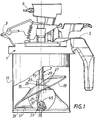
- the agitator cover 1 represented is of a classic model (except the agitator), comprising a pouring spout 3, a handling handle 5 to the end diametrically opposite the spout, and an axis agitator 7 in vertical axial position.
- the axis is driven by an upper pinion 9, itself engaged with a chain continuous (not shown) of a stirring machine on which the cover is mounted.
- This cover receives a lower shade 11.
- the agitator axis 7 consists of an axial rod 13 and a lower agitating blade 15.
- the blade 15 is mounted movable in translation on the axis rod 13 in its part lower so as to descend under the hydrodynamic action agitation towards the bottom 17 of the box (flat surface horizontal) at a short distance from it.
- the rod 13 has a determined length constant, allowed thanks to the mounting in translation of the pale and suitable for use with various boxes in a given capacity range, the height of these varying slightly from one manufacturer to another.
- the blade 15 is of the generator type 19 in the form of spiral whose mixing efficiency allows the use without having to vibrate the agitator axis 7, which required in the prior art known a mounting in blade suspension with corresponding adaptation in height to each box.
- the blade 15 is slidably mounted longitudinally by its central shaft 21 on the rod of the agitator axis, this on a stroke determined.
- This bole 21 has two shoulders longitudinal 23 diametrically opposite each provided with a internal groove 25 receiving a complementary rib 27 of the stem. Upward translation is limited by a upper stop 29 at the upper end of each of the grooves, and similarly down by a stop lower.
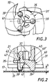
- the blade 15 further comprises at the lower end of its axial shaft 21 a lower bearing end piece 31 mounted to rotate freely on the latter and which projects downwards under the horizontal lower rectilinear edge 33 of the blade.
- the distance h between the lower horizontal plane of the nozzle and the lower edge 33 of the blade is determined according to the latter and the paint to be treated (to a lesser extent) so as to obtain optimum efficiency stirring.
- the end piece 31 comprises (FIGS. 2 and 3) a body part disc-shaped or circular plate 35, diameter equivalent to that of the barrel 21 of the blade 15, three elements to upper snap hook 37 (clip tabs) on a same circle at 120 ° from each other, arranged vertically on the central part of the plate 35, and three lower fingers 39 arranged vertically under the plate 35 and also on the same circle at 120 ° angle one of the other.
- the whole has an axial symmetry, from molding in a low synthetic material coefficient of friction (based on "Teflon").
- the fingers 39 have their rounded end and come to the during the agitation apply occasionally on the bottom surface 17 of the box (in a perpendicular plane to the axis). They are arranged substantially on the periphery of the plate 35, being rigidly held thereon by radial ribs 41. Their lateral arrangement increases the bonding torque adherent to the bottom of the box, against all rotary sliding on this background.
- the upper hook elements 37 constitute the part of rotary connection of the nozzle on the blade. They have their upper hook nose 43 facing radially towards the exterior and come into engagement by snapping into the cylindrical skirt 45 internal lower complementary to the barrel pale.
- This skirt 45 is developed vertically enclosing with slight play the vertical legs of the elements hooks 37 in its lower part of reduced diameter 47 and receiving in a larger overlying part diameter of hook noses 43.
- This hooking assembly of the tip on the blade shaft has a suitable clearance, of a part for the rotation travel and, secondly, for the travel in seat plane of the nozzle on the surface background 17.
- the relative rotary sliding of the nozzle and the blade is performed between the facing horizontal surfaces respectively 49, 49 'of the barrel lower end of the blade and the corresponding upper surface of the platinum.
- the sliding torque is very low, well less than the sliding torque of the support points fingers 39 on the bottom surface 17 of the box.
- the mounting snap-on end cap due to the mounting snap-on end cap, it can be removed easily, by simply removing it using a screwdriver blade, for example to replace it in case of wear or by a nozzle of different height depending on the paint treated.
- the tip can be alternatively mounted directly on the axle rod agitator, at its lower end, and not on the blade, the telescopically sliding axis with a fixed blade on the axis or the blade sliding in translation on the axis.
Landscapes
- Chemical & Material Sciences (AREA)
- Chemical Kinetics & Catalysis (AREA)
- Mixers Of The Rotary Stirring Type (AREA)
- Accessories For Mixers (AREA)
- Food-Manufacturing Devices (AREA)
- Closures For Containers (AREA)
- Coating Apparatus (AREA)
- Nozzles (AREA)
Claims (11)
- Rührdeckel für Farbbehälter, befestigt auf Farbrührmaschinen, wobei der Rührdeckel so beschaffen ist, daß er folgendes aufweist: eine Rührachse (7), welche frei beweglich in Translation relativ zum Deckel angeordnet ist und mit einem Axialschaft (13) versehen ist, welcher eine Drehbewegung ausführt und weiter mit einem tieferangeordneten Rührschaufelblatt (15), wobei die Rührachse (7) unter Druckeinwirkung durch das Rührschaufelblatt im Verlauf des Rührvorgangs zum Einnehmen einer Position gegen ein Widerlager, welches sich auf dem Behälterboden (17) befindet, fähig ist, dadurch gekennzeichnet, daß die Rührachse (7) an ihrem unteren Ende eine Anbringungszwinge (31) am Behälterboden aufweist, wobei diese Zwinge eine freie Drehbewegung auf der Rührachse (7) ausführen kann und mit mindestens drei tiefer angeordneten vorspringenden Bauteilen (39) versehen ist, welche fähig sind, über eine gleiche Ebene, welche senkrecht zur Achse angeordnet ist, in Kontakt mit der Oberfläche des Behälterbodens (17) zu kommen.
- Rührdeckel nach Anspruch 1, dadurch gekennzeichnet, daß die Zwinge (31) in freier Drehbewegung koaxial zur Rührachse (7) angeordnet ist.
- Rührdeckel nach den Ansprüchen 1 oder 2, dadurch gekennzeichnet, daß die vorspringenden Bauteile (39) in punktförmigen Kontakt mit dem Behälterboden (17) kommen.
- Rührdeckel nach einem der Ansprüche 1 bis 3, dadurch gekennzeichnet, daß die Zwinge (31) eine Hohenabmessung aufweist, welche in Relation zum Schaufelblatt (15) bestimmt ist, wobei die Höhe des Schaufelblatts so bestimmt ist, daß eine optimale Funktionsweise relativ zur Oberfläche des Behälterbodens geschaffen wird.
- Rührdeckel nach einem der vorhergehenden Ansprüche, dadurch gekennzeichnet, daß die Zwinge (31) eine kreisförmige Platte (35) ist, deren Durchmesser etwas größer als der Durchmesser des Schafts (13) der Rührachse ist, nämlich 4 bis 15 mm, und die kreisförmige Platte senkrecht zur Drehachse angebracht ist, wobei die vorspringenden Bauteile (39) zylinderförmige Zapfen sind, deren äußere Enden abgerundet sind, und die Zapfen kreisförmig in einem Winkel von 120° zueinander angeordnet sind.
- Rührdeckel nach einem der vorhergehenden Ansprüche, dadurch gekennzeichnet, daß die drehbare Befestigung der Zwinge (31) auf der Rührachse (5) mit Hilfe einer Sperrvorrichtung (37), welche im Eingriff mit einer Bohrung (45, 47) des Kolbens am Rührachsenende (7) ist, sichergestellt wird.
- Rührdeckel nach Anspruch 6, dadurch gekennzeichnet, daß die Sperrvorrichtung (37) einen kreisförmigen Aufbau aufweist, bestehend aus drei obenliegenden Laschenklemmen, welche auf dem obenliegenden Mittelteil der Zwinge (31) befestigt sind und deren obenangeordneter Formnasenteil (43) mit einem zusätzlichen zylinderförmigen Kolbenmantel (45) des Achsenkolbens im Eingriff steht.
- Rührdeckel nach einem der vorhergehenden Ansprüche, dadurch gekennzeichnet, daß die Rührachse (7) mit einem Schaufelblatt (15), welches einen spiralförmigen Aufbau aufweist, versehen ist, nämlich mit einem Generator in Form einer Spirale, wobei das spiralförmige Schaufelblatt (15) an seinem unteren Ende beweglich in Translation auf dem Schaft (13) der Rührachse befestigt ist, und die Zwinge (31) drehbar auf dem Schaufelblatt (15) an deren unteren Ende befestigt ist, und zwar in koaxialer Ausrichtung zum Schaufelblatt, wobei die Zwinge mit ihrer unteren Stirnkante (33) mit einer bestimmten Höhe h, welche der Höhe der Farbmenge auf dem Behälterboden (17) entspricht, hinausragt und so ein optimaler Betrieb möglich ist.
- Rührdeckel nach Anspruch 8, dadurch gekennzeichnet, daß der Schaft (13) der Rührachse eine bestimmte konstante Länge aufweist, welche je nach Verwendung bei verschiedenen Behältern (11) innerhalb einer Skala bezüglich des vorgegebenen Fassungsraum angepaßt wird.
- Rührdeckel nach einem der Ansprüche 8 und 9, dadurch gekennzeichnet, daß das Schaufelblatt (15) mit Hilfe seines Zentralkolbens (21) auf dem Schaft (13) der Rührachse in Längsrichtung in einem bestimmten Verlauf verschiebbar ist, wobei der Kolben (21) zwei an diametralen Stellen gegenüberliegende Längsvorsprünge (23) aufweist, welche beide mit einer Innennut (25) für die Aufnahme einer zusätzlichen Rippe (27) des Schafts versehen sind, wobei die Translation in Höhenrichtung durch ein höherangeordnetes Widerlager (29) am oberen Ende einer jeden Nut begrenzt ist, und ebenfalls in Abwärtsrichtung durch das Auftreffen auf ein tieferangeordnetes Widerlager.
- Rührdeckel nach einem der vorhergehenden Ansprüche, dadurch gekennzeichnet, daß die Zwinge (31) eine Symmetrieachse aufweist, welche eine Abflußöffnung aus einem Kunststoff mit einem geringen Reibungskoeffizienten ist.
Applications Claiming Priority (2)
| Application Number | Priority Date | Filing Date | Title |
|---|---|---|---|
| FR9609218 | 1996-07-23 | ||
| FR9609218A FR2751563B1 (fr) | 1996-07-23 | 1996-07-23 | Couvercle agitateur pour boite de teinte sur les machines d'agitation de peinture |
Publications (2)
| Publication Number | Publication Date |
|---|---|
| EP0820879A1 EP0820879A1 (de) | 1998-01-28 |
| EP0820879B1 true EP0820879B1 (de) | 1999-09-01 |
Family
ID=9494350
Family Applications (1)
| Application Number | Title | Priority Date | Filing Date |
|---|---|---|---|
| EP97401625A Expired - Lifetime EP0820879B1 (de) | 1996-07-23 | 1997-07-08 | Rührdeckel für Farbbehälter, befestigt auf Farbrührmaschinen |
Country Status (10)
| Country | Link |
|---|---|
| US (1) | US5839825A (de) |
| EP (1) | EP0820879B1 (de) |
| JP (1) | JP3973736B2 (de) |
| CN (1) | CN1105036C (de) |
| AT (1) | ATE183968T1 (de) |
| AU (1) | AU720682B2 (de) |
| BR (1) | BR9705227A (de) |
| CA (1) | CA2210512A1 (de) |
| DE (1) | DE69700463T2 (de) |
| FR (1) | FR2751563B1 (de) |
Families Citing this family (18)
| Publication number | Priority date | Publication date | Assignee | Title |
|---|---|---|---|---|
| US6053218A (en) * | 1998-11-10 | 2000-04-25 | X-Pert Paint Mixing Systems, Inc. | Semi-automated system for dispensing automotive paint |
| US6095373A (en) * | 1998-11-10 | 2000-08-01 | X-Pert Paint Mixing Systems, Inc. | Paint container lid for a semi-automated automotive paint dispensing system |
| US6290110B1 (en) | 1999-10-13 | 2001-09-18 | X-Pert Paint Mixing Systems, Inc. | Fluid seal for a pour spout of a paint container lid member |
| US6234218B1 (en) | 1999-10-13 | 2001-05-22 | X-Pert Paint Mixing Systems, Inc. | Semi-automated automotive paint dispensing system |
| US6146009A (en) * | 1999-10-13 | 2000-11-14 | X-Pert Paint Mixing Systems, Inc. | Paint container lid member adaptable for use with a plurality of paint mixing systems |
| US6206250B1 (en) | 1999-10-13 | 2001-03-27 | X-Pert Paint Mixing Systems, Inc. | Lid member for a paint container useable with a semi-automated automotive paint dispensing system |
| DE60125852D1 (de) * | 2000-04-06 | 2007-02-22 | Fast & Fluid Man S R L | Abmessvorrichtung für den Deckel eines Wassereimers oder lösungsmittelhaltige Farbe |
| US7318668B2 (en) * | 2003-05-15 | 2008-01-15 | Woodman Agitator Incorporated | Agitator-incorporating container |
| US8424704B2 (en) * | 2004-06-02 | 2013-04-23 | X-Pert Paint Mixing Systems, Inc. | Self-cleaning lid for a paint container fluid pour spout |
| EP1885567B1 (de) * | 2005-05-11 | 2009-08-12 | Fillon Investissement | Eine giessschnauze umfassender präzisionsdeckel, der zum schliessen eines flüssigkeit oder ein teilchenförmiges produkt enthaltenden behälters verwendet wird |
| TW200714351A (en) * | 2005-10-07 | 2007-04-16 | Duen-Gang Mou | A small portable stirred reaction device with high power input |
| GB2434997A (en) * | 2006-02-11 | 2007-08-15 | Daniel Bolton | Paint stirring tin |
| US20070217283A1 (en) * | 2006-03-16 | 2007-09-20 | David Eaton | Paint stirrer system |
| FR2960863B1 (fr) | 2010-06-07 | 2012-07-13 | Fillon Technologies | Couvercle de fermeture pour recipient equipe d'un joint d'etancheite |
| CN104985979A (zh) * | 2015-07-09 | 2015-10-21 | 安徽海澄德畅电子科技有限公司 | 一种颜料混合回流搅拌装置 |
| CN107264171A (zh) * | 2017-08-17 | 2017-10-20 | 重庆白鲸数码科技有限公司 | 一种辅助绘画调色的机器人 |
| DE202019104121U1 (de) | 2019-07-26 | 2019-08-06 | Dominic Nindl | Rührhilfe für Flüssigfarben |
| JP7582832B2 (ja) * | 2020-10-14 | 2024-11-13 | 住友重機械プロセス機器株式会社 | 撹拌装置 |
Family Cites Families (10)
| Publication number | Priority date | Publication date | Assignee | Title |
|---|---|---|---|---|
| US569428A (en) * | 1896-10-13 | Paint-mixer | ||
| US1775345A (en) * | 1929-10-22 | 1930-09-09 | Abraham L Henschel | Calcimine mixer |
| US2027297A (en) * | 1935-06-10 | 1936-01-07 | Tramposch Frank | Paint mixer |
| US2814473A (en) * | 1955-05-25 | 1957-11-26 | Harold J Kroll | Fluid agitator |
| US4380399A (en) * | 1980-01-07 | 1983-04-19 | Fonderie Et Ateliers Des Sablons | Mixer for homogenizing a mixture of products contained in a vessel |
| FR2475502A1 (fr) * | 1980-02-11 | 1981-08-14 | Sablons Fonderies Atel | Couvercle de recipient notamment pour agitateur servant a l'homogeneisation d'un melange de produits |
| CA1280109C (en) * | 1987-07-08 | 1991-02-12 | Laszlo Murzsa | Paint mixing container |
| FR2645832B1 (fr) * | 1989-04-18 | 1991-08-16 | Sablons Fonderies Atel | Couvercle agitateur notamment pour les boites de teintes de laques en carrosserie automobile, a agitateur mobile axialement |
| US5358153A (en) * | 1991-12-30 | 1994-10-25 | E. I. Du Pont De Nemours And Company | Mixing lid including a pouring device for containers used on stirring machines |
| CA2102073A1 (fr) * | 1993-10-29 | 1995-04-30 | Alain Krzywdzjak | Dispositif d'accouplement reglable de l'entrainement de la tige d'axe agitateur des dispositifs agitateurs, sur les machines d'agitation de peinture |
-
1996
- 1996-07-23 FR FR9609218A patent/FR2751563B1/fr not_active Expired - Fee Related
-
1997
- 1997-04-25 CN CN97109737A patent/CN1105036C/zh not_active Expired - Fee Related
- 1997-07-08 DE DE69700463T patent/DE69700463T2/de not_active Expired - Lifetime
- 1997-07-08 AT AT97401625T patent/ATE183968T1/de not_active IP Right Cessation
- 1997-07-08 EP EP97401625A patent/EP0820879B1/de not_active Expired - Lifetime
- 1997-07-09 JP JP18357197A patent/JP3973736B2/ja not_active Expired - Fee Related
- 1997-07-11 CA CA002210512A patent/CA2210512A1/fr not_active Abandoned
- 1997-07-21 AU AU28777/97A patent/AU720682B2/en not_active Ceased
- 1997-07-22 BR BR9705227A patent/BR9705227A/pt not_active IP Right Cessation
- 1997-07-23 US US08/899,234 patent/US5839825A/en not_active Expired - Lifetime
Also Published As
| Publication number | Publication date |
|---|---|
| JPH1076800A (ja) | 1998-03-24 |
| FR2751563A1 (fr) | 1998-01-30 |
| ATE183968T1 (de) | 1999-09-15 |
| FR2751563B1 (fr) | 1998-09-25 |
| JP3973736B2 (ja) | 2007-09-12 |
| CA2210512A1 (fr) | 1998-01-23 |
| EP0820879A1 (de) | 1998-01-28 |
| US5839825A (en) | 1998-11-24 |
| DE69700463D1 (de) | 1999-10-07 |
| AU720682B2 (en) | 2000-06-08 |
| AU2877797A (en) | 1998-01-29 |
| CN1171333A (zh) | 1998-01-28 |
| CN1105036C (zh) | 2003-04-09 |
| BR9705227A (pt) | 1999-03-16 |
| DE69700463T2 (de) | 2000-04-13 |
Similar Documents
| Publication | Publication Date | Title |
|---|---|---|
| EP0820879A1 (de) | Rührdeckel für Farbbehälter, befestigt auf Farbrührmaschinen | |
| EP0032137B1 (de) | Rührer zum Homogenisieren von Mischungen in einem Behälter | |
| EP0911080B1 (de) | Zentrifuge mit abnehmbarem Rotor und einer Einrichtung zur axialen Verriegelung des Rotors auf der Antriebswelle, sowie Rotor für eine solche Zentrifuge | |
| EP0876122B1 (de) | Elektrische küchenmaschine zum zubereiten von nahrungsmitteln, wie eine mehrzweckküchenmaschine mit einem tragelement für die rotierende arbeitsvorrichtung | |
| FR2715867A1 (fr) | Dispositif pour mélanger et préparer des matériaux susceptibles de s'écouler. | |
| EP1139838A1 (de) | Mehrzweckküchenmaschine | |
| EP0021914B1 (de) | Scheibenwischer, insbesondere für Kraftfahrzeuge | |
| WO2000027264A1 (fr) | Broyeur manuel pour des produits alimentaires en grains | |
| EP0394087B1 (de) | Rührerdeckel, insbesondere für Farbenschachteln für Autokarosserielacke mit axial bewegbarem Rührer | |
| EP0788950B1 (de) | Kraftfahrzeug-Scheibenwischervorrichtung mit Scheibenwischer-Indexierungsmittelnunter Berücksichtigung der Antriebswelle | |
| CA2101798A1 (fr) | Bras d'essuie-glace, notamment pour vehicule a grande vitesse | |
| EP1017302B1 (de) | Elektrische küchenmaschine zum zubereiten von nahrungsmitteln, wie eine mehrzweckküchenmaschine mit einem tragelement für die rotierende arbeitsvorrichtung | |
| FR2754165A1 (fr) | Appareil electromenager de preparation culinaire, du genre robot menager multi-usages | |
| FR2607794A1 (fr) | Bec de remplissage notamment pour machine a dosage ponderal | |
| FR2729905A1 (fr) | Dispositif d'essuie-glace comportant des moyens perfectionnes de demontage de sa tete d'entrainement | |
| EP0211704B1 (de) | Zündverteilerrotor für Brennkraftmaschine | |
| EP0094264A2 (de) | Siebvorrichtung zur Entfernung von Feststoffteilchen aus einer Flüssigkeit | |
| WO2023046921A1 (fr) | Appareil de preparation culinaire comportant un accessoire entraine en rotation | |
| FR2588500A1 (fr) | Malaxeur-melangeur a beton a flux contrarie | |
| FR2759930A1 (fr) | Instrument a main pour l'ebavurage interieur de pieces cylindriques | |
| FR2780128A1 (fr) | Poulie relais pour la transmission sans fin de puissance a vitesse variable | |
| FR2481911A1 (fr) | Presse-agrumes manuel a mouvement rotatoire alternatif | |
| FR2758477A1 (fr) | Installation d'agitation pour un conteneur | |
| FR2495495A2 (fr) | Agitateur destine a homogeneiser un melange de produits contenu dans un recipient | |
| EP3845103A1 (de) | Mischvorrichtung |
Legal Events
| Date | Code | Title | Description |
|---|---|---|---|
| PUAI | Public reference made under article 153(3) epc to a published international application that has entered the european phase |
Free format text: ORIGINAL CODE: 0009012 |
|
| AK | Designated contracting states |
Kind code of ref document: A1 Designated state(s): AT BE CH DE ES GB IT LI LU NL SE |
|
| AX | Request for extension of the european patent |
Free format text: AL;LT;LV;RO;SI |
|
| 17P | Request for examination filed |
Effective date: 19980330 |
|
| RBV | Designated contracting states (corrected) |
Designated state(s): AT BE CH DE ES GB IT LI LU NL SE |
|
| GRAG | Despatch of communication of intention to grant |
Free format text: ORIGINAL CODE: EPIDOS AGRA |
|
| GRAG | Despatch of communication of intention to grant |
Free format text: ORIGINAL CODE: EPIDOS AGRA |
|
| GRAH | Despatch of communication of intention to grant a patent |
Free format text: ORIGINAL CODE: EPIDOS IGRA |
|
| 17Q | First examination report despatched |
Effective date: 19990128 |
|
| GRAH | Despatch of communication of intention to grant a patent |
Free format text: ORIGINAL CODE: EPIDOS IGRA |
|
| GRAA | (expected) grant |
Free format text: ORIGINAL CODE: 0009210 |
|
| RAP1 | Party data changed (applicant data changed or rights of an application transferred) |
Owner name: SOCIETE ANONYME DITE: F.A.S. |
|
| AK | Designated contracting states |
Kind code of ref document: B1 Designated state(s): AT BE CH DE ES GB IT LI LU NL SE |
|
| PG25 | Lapsed in a contracting state [announced via postgrant information from national office to epo] |
Ref country code: SE Free format text: THE PATENT HAS BEEN ANNULLED BY A DECISION OF A NATIONAL AUTHORITY Effective date: 19990901 Ref country code: ES Free format text: THE PATENT HAS BEEN ANNULLED BY A DECISION OF A NATIONAL AUTHORITY Effective date: 19990901 Ref country code: AT Free format text: LAPSE BECAUSE OF FAILURE TO SUBMIT A TRANSLATION OF THE DESCRIPTION OR TO PAY THE FEE WITHIN THE PRESCRIBED TIME-LIMIT Effective date: 19990901 |
|
| REF | Corresponds to: |
Ref document number: 183968 Country of ref document: AT Date of ref document: 19990915 Kind code of ref document: T |
|
| REG | Reference to a national code |
Ref country code: CH Ref legal event code: EP |
|
| REF | Corresponds to: |
Ref document number: 69700463 Country of ref document: DE Date of ref document: 19991007 |
|
| ITF | It: translation for a ep patent filed | ||
| GBT | Gb: translation of ep patent filed (gb section 77(6)(a)/1977) |
Effective date: 19991207 |
|
| PLBE | No opposition filed within time limit |
Free format text: ORIGINAL CODE: 0009261 |
|
| STAA | Information on the status of an ep patent application or granted ep patent |
Free format text: STATUS: NO OPPOSITION FILED WITHIN TIME LIMIT |
|
| PG25 | Lapsed in a contracting state [announced via postgrant information from national office to epo] |
Ref country code: LU Free format text: LAPSE BECAUSE OF NON-PAYMENT OF DUE FEES Effective date: 20000708 |
|
| PG25 | Lapsed in a contracting state [announced via postgrant information from national office to epo] |
Ref country code: BE Free format text: LAPSE BECAUSE OF NON-PAYMENT OF DUE FEES Effective date: 20000731 |
|
| 26N | No opposition filed | ||
| BERE | Be: lapsed |
Owner name: F.A.S. Effective date: 20000731 |
|
| PG25 | Lapsed in a contracting state [announced via postgrant information from national office to epo] |
Ref country code: LI Free format text: LAPSE BECAUSE OF NON-PAYMENT OF DUE FEES Effective date: 20010731 Ref country code: CH Free format text: LAPSE BECAUSE OF NON-PAYMENT OF DUE FEES Effective date: 20010731 |
|
| REG | Reference to a national code |
Ref country code: GB Ref legal event code: IF02 |
|
| REG | Reference to a national code |
Ref country code: CH Ref legal event code: PL |
|
| PGFP | Annual fee paid to national office [announced via postgrant information from national office to epo] |
Ref country code: NL Payment date: 20030630 Year of fee payment: 7 |
|
| PG25 | Lapsed in a contracting state [announced via postgrant information from national office to epo] |
Ref country code: NL Free format text: LAPSE BECAUSE OF NON-PAYMENT OF DUE FEES Effective date: 20050201 |
|
| NLV4 | Nl: lapsed or anulled due to non-payment of the annual fee |
Effective date: 20050201 |
|
| PGFP | Annual fee paid to national office [announced via postgrant information from national office to epo] |
Ref country code: IT Payment date: 20080726 Year of fee payment: 12 |
|
| PGFP | Annual fee paid to national office [announced via postgrant information from national office to epo] |
Ref country code: GB Payment date: 20080722 Year of fee payment: 12 |
|
| GBPC | Gb: european patent ceased through non-payment of renewal fee |
Effective date: 20090708 |
|
| PG25 | Lapsed in a contracting state [announced via postgrant information from national office to epo] |
Ref country code: GB Free format text: LAPSE BECAUSE OF NON-PAYMENT OF DUE FEES Effective date: 20090708 |
|
| PGFP | Annual fee paid to national office [announced via postgrant information from national office to epo] |
Ref country code: DE Payment date: 20100723 Year of fee payment: 14 |
|
| PG25 | Lapsed in a contracting state [announced via postgrant information from national office to epo] |
Ref country code: IT Free format text: LAPSE BECAUSE OF NON-PAYMENT OF DUE FEES Effective date: 20090708 |
|
| PG25 | Lapsed in a contracting state [announced via postgrant information from national office to epo] |
Ref country code: DE Free format text: LAPSE BECAUSE OF NON-PAYMENT OF DUE FEES Effective date: 20120201 |
|
| REG | Reference to a national code |
Ref country code: DE Ref legal event code: R119 Ref document number: 69700463 Country of ref document: DE Effective date: 20120201 |