EP0820911A2 - Scheinwerfer-Reinigungseinrichtung - Google Patents
Scheinwerfer-Reinigungseinrichtung Download PDFInfo
- Publication number
- EP0820911A2 EP0820911A2 EP97111090A EP97111090A EP0820911A2 EP 0820911 A2 EP0820911 A2 EP 0820911A2 EP 97111090 A EP97111090 A EP 97111090A EP 97111090 A EP97111090 A EP 97111090A EP 0820911 A2 EP0820911 A2 EP 0820911A2
- Authority
- EP
- European Patent Office
- Prior art keywords
- nozzle
- tube
- cleaning device
- working position
- headlight
- Prior art date
- Legal status (The legal status is an assumption and is not a legal conclusion. Google has not performed a legal analysis and makes no representation as to the accuracy of the status listed.)
- Granted
Links
Images


Classifications
-
- B—PERFORMING OPERATIONS; TRANSPORTING
- B60—VEHICLES IN GENERAL
- B60S—SERVICING, CLEANING, REPAIRING, SUPPORTING, LIFTING, OR MANOEUVRING OF VEHICLES, NOT OTHERWISE PROVIDED FOR
- B60S1/00—Cleaning of vehicles
- B60S1/02—Cleaning windscreens, windows or optical devices
- B60S1/46—Cleaning windscreens, windows or optical devices using liquid; Windscreen washers
- B60S1/48—Liquid supply therefor
- B60S1/487—Liquid supply therefor the liquid being heated
- B60S1/488—Liquid supply therefor the liquid being heated electrically
-
- B—PERFORMING OPERATIONS; TRANSPORTING
- B60—VEHICLES IN GENERAL
- B60S—SERVICING, CLEANING, REPAIRING, SUPPORTING, LIFTING, OR MANOEUVRING OF VEHICLES, NOT OTHERWISE PROVIDED FOR
- B60S1/00—Cleaning of vehicles
- B60S1/02—Cleaning windscreens, windows or optical devices
- B60S1/46—Cleaning windscreens, windows or optical devices using liquid; Windscreen washers
- B60S1/48—Liquid supply therefor
- B60S1/52—Arrangement of nozzles; Liquid spreading means
- B60S1/522—Arrangement of nozzles; Liquid spreading means moving liquid spreading means, e.g. arranged in wiper arms
- B60S1/528—Arrangement of nozzles; Liquid spreading means moving liquid spreading means, e.g. arranged in wiper arms the spreading means being moved between a rest position and a working position
-
- B—PERFORMING OPERATIONS; TRANSPORTING
- B60—VEHICLES IN GENERAL
- B60S—SERVICING, CLEANING, REPAIRING, SUPPORTING, LIFTING, OR MANOEUVRING OF VEHICLES, NOT OTHERWISE PROVIDED FOR
- B60S1/00—Cleaning of vehicles
- B60S1/02—Cleaning windscreens, windows or optical devices
- B60S1/56—Cleaning windscreens, windows or optical devices specially adapted for cleaning other parts or devices than front windows or windscreens
- B60S1/60—Cleaning windscreens, windows or optical devices specially adapted for cleaning other parts or devices than front windows or windscreens for signalling devices, e.g. reflectors
- B60S1/603—Cleaning windscreens, windows or optical devices specially adapted for cleaning other parts or devices than front windows or windscreens for signalling devices, e.g. reflectors the operation of at least a part of the cleaning means being controlled by electric means
Definitions
- the invention relates to a headlight cleaning device for vehicles according to the features of the respective preamble of the independent claims.
- Such a headlight cleaning device for vehicles is from the DE-OS 24 55 294 known.
- this system there is a nozzle, which in a rest position and is movable into a working position. This movement is effected by an actuating device, which has a lever in a guide drives stored tube.
- This cleaning system is structurally complex, since it contains many individual components and requires a high one Installation space, particularly in the front area of the vehicle, in the usually the headlights are arranged, is not available.
- it is disadvantageous that the cleaning system is dirty is subjected, which leads to an impairment of the functioning can come.
- Another disadvantage is that the movement of the Actuator translates acts on the tube so that when the nozzle is in frozen or dirty in its rest position, the movement into the Working position is difficult or even not possible.
- the invention is therefore based on the object of a headlight cleaning device in such a way that the disadvantages mentioned are avoided be, as well as to provide a suitable method for operating.
- the actuating device in particular a pneumatic or hydropneumatic control device or the electric motor known per se
- the carrier in particular the pipe that drives down.
- the electric motor is arranged in a housing, the tube penetrating the housing at least once. Because of In this embodiment, the cleaning device can be compact Unit are prefabricated and thus enables simplified assembly.
- the tube penetrates the housing twice, this penetration then being designed as a guide for the tube is. This penetration (or penetrations) serves as a guide of the tube in a smooth-walled design of the tube also as Sealing against external influences. A separate tour of the Carrier (tube) is also conceivable.
- the housing consists of two half shells, these half-shells being symmetrical.
- This configuration has the advantage that simple assembly is possible.
- the connection of the two half-shells with one another, if necessary with the insertion of one Seal, in a known manner by screwing, gluing, snapping or the like. are in a suitable manner per se Lines led out of the housing at least for the electric motor.
- the tube is symmetrical. This has also the advantage of a simple assembly, because no attention is paid to it at which end of the pipe the nozzle and at which end the Supply hose for the cleaning liquid must be connected. To this is the purpose of at least the nozzle on the pipe geometry adjust in the end area.
- the Pipe have a stop that is in one position, preferably in the working position on a further stop, in particular on a housing stop, is present.
- limit switches that for example, operated by the attacks. These are preferably Arrange limit switches within the housing.
- a pressure-dependent valve In a development of the invention is in the flow area of the tube or Nozzle arranged a pressure-dependent valve. This has the advantage that cleaning fluid is then only dispensed (sprayed) from the nozzle, if a predeterminable pressure has been built up that overcomes the valve. This ensures that only cleaning fluid with such a Pressure on the headlights (lenses) is sprayed for reliable Cleaning is required.
- a protective cover especially a bellows.
- This has the advantage that the Area in which the actuator is located and the is guided by the guide, from contamination and thus from one increased wear is protected.
- a protective cover is a bellows, and also other configurations are conceivable. Depending on the dimensioning of the protective cover this can cause the movement of the pipe due to its spring force support.
- the actuating device is in the working position energy can be applied to the nozzle at least temporarily.
- energy can be applied to the nozzle at least temporarily.
- the electric motor after the linear movement of the tube the rest position in the working position is still energized in order to in addition to the system of the pipe at one stop, additional stability to accomplish. It is conceivable to only energize the electric motor if cleaning liquid is also dispensed through the nozzle or during the total time the pipe is in the working position to energize.
- a method for operating a headlight cleaning device at which the nozzle in the working position at least temporarily cleaning liquid emits, provides that the nozzle also during the movement from the rest position dispenses cleaning fluid into the working position and / or vice versa.
- This allows, for example, a linear movement when extending cleaning liquid is already sprayed onto the lens, there dissolve the dirt, which is then from the hosed cleaning liquid is largely completely eliminated in the working position of the nozzle.
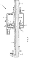
- Fig. 1 shows a headlight cleaning device in the extended state with their essential components, with which also the invention Procedure can be realized.
- a housing 2 For the essential components of a headlight cleaning device 1 is a housing 2, the housing 2 being surrounded by a tube 3 is enforced. At one end of the tube 3 (in the area of the not shown Headlamp, in its housing also the headlamp cleaning direction can be integrated) a nozzle 4 is arranged, which any Type (e.g. a so-called Fluidics nozzle with the advantage of the conventional nozzles with lower consumption of cleaning fluid) can be.
- This nozzle 4 can be an independent component, conceivable it is also that the tube 3 and the nozzle 4 form a structural unit or are made in one piece.
- a connector 5 for a supply hose for cleaning liquid available the connector in a manner known per se Has abutment for the supply hose to prevent it from jumping off.
- a stop 6 (for the nozzle 4) and a stop 7 are in the housing 2 (for the connector 5) integrated, these stops 6 and 7 the guide or a seal of a smooth-walled tube 3 with respect to the housing 2 take over.
- In the area of the stop 7 there is, for example Conical training shown, while in the area of the stop 6 corresponding 4 stop surfaces arranged on the nozzle.
- the Conical training has the advantage that the tube 3 in the extended Position is stabilized.
- an electric motor 8 is arranged, which is not closer to it designated motor shaft carries a pinion 9.
- This pinion 9 is in meshing engagement with a spur gear 10, the spur gear 10 on its tube 3 assigned inner circumference is designed as a worm wheel 11.
- This Worm wheel 11 in turn meshes with a worm 12, whose screw flights are arranged over such a partial length of the tube 3 are around the pipe 3 and thus the nozzle 4 from the rest position to the working position, shown in this figure to move linearly.
- the worm wheel 11 (or the spur gear forming a structural unit) is such a way 10) guided, this guide on the one hand from part of the stop 6 and on the other hand is taken over by a separate guide 13.
- the tube 3 Rack is arranged or integrated by the electric motor 2, if necessary with the interposition of further gears that have a reduction form, is driven. It is also conceivable that the electric motor 2 drives a friction wheel that acts on a smooth-walled tube. Furthermore can along the tube 3 (for example in the form of a jacket) or a heater is integrated in the tube 3 (for example in the form of resistance wires) be integrated. This resistance heater can be below one Predeterminable temperature threshold are operated continuously, it also it is conceivable that this resistance heating only when the electric motor is actuated turn on.
- a pressure-generating is advantageously Device (delivery device) that the cleaning liquid through the pipe 3 and through the nozzle 4 to the headlight, only switched on, when the tube 3 and thus the nozzle 4 are in their working position. It is not necessarily required that the tube 3 in its the nozzle 4 facing Area is just formed, but here are thickenings, Tapered or other geometrical designs (e.g. arch shape) conceivable to the outer contours of the vehicle in the nozzle area To be able to adjust the headlight area.
- FIG. 2 shows a further embodiment of a headlight cleaning device.
- the Stop 7 and the connecting piece 5 also arranged a bellows 14, which is retracted in the working position shown in FIG. 2.
- valve 15 is arranged in the nozzle 4, the pressure-dependent, so that cleaning liquid from the nozzle 4 only with a predetermined pressure is hosed. It is conceivable, the valve 15 too in the area of the tube 3 or in an area behind a not shown Arrange conveyor for cleaning liquid and the tube 3.
- the reference number 16 designates an electrical connection which connects the supply lines for the power supply of the electric motor 8 and possibly additional lines (for example for limit switches, not shown) the housing 2 leads.
- This electrical connection 16 is particularly dust and waterproof.
- Fig. 2 In addition to Fig. 1 is shown in Fig. 2 that the reduction gear a further reduction stage in the form of a gear wheel 17 has, the larger ring gear of the gear 17 meshes the pinion 9 and the smaller ring gear of the gear 17 meshes the spur gear 10.
- FIG. 3 shows a section BB through the configuration according to FIG. 2, wherein a two-part housing 2, the electric motor 8, the gear 17, the spur gear 10 and the tube 3 with the worm gear 12 is shown.
- FIG. 4 shows a time line diagram, an exemplary control for the electric motor 8 for achieving a linear movement being shown in FIG. 4a.
- the electric motor 8 receives a control pulse, so that, as shown in FIG. 4b, it moves the nozzle 4 from its rest position R into its working position A.
- the working position A is reached at a point in time t 1 , which is the case, for example, after the passage of time (t 0 to t 1 ) or can be detected by limit switches or the current consumption of the electric motor 8, a conveyor device for supplying the nozzle 4 with cleaning liquid or a Valve, via which a pressurized cleaning liquid is retained, switched on or controlled, as shown in FIG. 4c.
- the conveying device or the valve it is conceivable to control the conveying device or the valve not only during the time t 1 to t 2 during which the nozzle is in its working position, but also during the time period t 0 to t 1 and / or during the period t 2 to t 3 , so that the nozzle delivers and / or cleaning liquid even during the movement from the rest position R into the working position A.
- the nozzle 4 can deliver cleaning liquid once, several times or continuously.
- the dispensing of cleaning liquid around the time t 1 and / or t 2 is also conceivable.
- a preferred control is provided such that the nozzle 4 releases cleaning liquid once within the period t 1 to t 2 , in which it is in its working position A, and in order to cause a detachment of dirt and then cleaning liquid once again when it is run in delivers to the. to spray away loosened dirt, as shown in FIG. 4d.
- a control switch 18 with which the cleaning of the headlights or their lenses is to be triggered manually or automatically, is connected to a control device 19 which, for example, controls a conveying device for cleaning fluid in the form of a pump 20. Furthermore, the control device 19 also controls the electric motor 8, specifically in the manner in which this is to be carried out in accordance with the method according to the invention, as shown by way of example in FIG.
- the control device 19 controls, for example, the time spans t 0 to t 1 , t 1 to t 2 and t 2 to t 3 by the passage of time, by detection and evaluation of the current drawn by the electric motor 8, by means of limit switches which detect the end positions of the tube 3 and whose output signals are supplied to the control device 19, or equivalent and equivalent procedures.
- the control device 19 is also able to continue to energize the electric motor 8 during the time that the nozzle 4 is in its working position in order to achieve greater stability (this is shown in FIG. 4a by the dashed line in the area) t 1 to t 2 shown).
- the control device 19 is connected to a temperature sensor 21, a heater 22 of the tube 3 and / or the nozzle 4 being able to be switched on when the temperature falls below a predefinable temperature threshold.
- the invention is not directed to a single nozzle for cleaning a single one Headlights limited. So it is also provided according to the invention that with several nozzles, in particular with two nozzles, one nozzle from one Conveying device (pump 20) and / or via a valve (for example Solenoid valve, not shown) is supplied with cleaning fluid. Alternatively it is possible for at least two nozzles, if necessary, in the case of a plurality of nozzles with the interposition of one valve each assigned to a nozzle, is supplied by a single conveyor. Depending on the design of the Conveying device (for example dual pump) is first the one nozzle and then supplied the other nozzle with cleaning liquid so that the headlights are cleaned one after the other.
- a valve for example Solenoid valve, not shown
- control device 19 is designed accordingly, so that the pump 20th both headlights are switched on during the cleaning process and successively controlled the two electric motors 8 then present will. It is also conceivable that the multiple nozzles with the same or a different amount of cleaning liquid or that the control device 19 during the cleaning process of a lens controls several spreading discs of the same or different lengths from each other.
Landscapes
- Engineering & Computer Science (AREA)
- Mechanical Engineering (AREA)
- Water Supply & Treatment (AREA)
- Nozzles (AREA)
- Lighting Device Outwards From Vehicle And Optical Signal (AREA)
Abstract
Description
- Fig. 1:
- Eine Scheinwerfer-Reinigungseinrichtung im ausgefahrenen Zustand,
- Fig. 2:
- eine weitere Ausgestaltung einer Scheinwerfer-Reinigungseinrichtung,
- Fig. 3:
- einen Schnitt B - B durch die Ausgestaltung gemäß Fig. 2,
- Fig. 4:
- ein Zeitliniendiagramm,
- Fig. 5:
- eine Steuereinrichtung.
Claims (17)
- Scheinwerfer-Reinigungseinrichtung (1) für Fahrzeuge mit zumindest einer im oder am Fahrzeug in Ruhestellung bringbaren, isnbesondere versenkbaren und in eine Arbeitsstellung mittels einer Stelleinrichtung bewegbaren Düse (4), wobei die Stelleinrichtung einen die Düse (4) aufnehmenden Träger, insbesondere ein Rohr (3), antreibt, dadurch gekennzeichnet, daß die Stelleinrichtung, insbesondere ein Elektromotor (8), den Träger [das Rohr (3)] untersetzt antreibt.
- Scheinwerfer-Reinigungseinrichtung (1) nach Anspruch 1, dadurch gekennzeichnet, daß der Elektromotor (8) in einem Gehäuse (2) angeordnet ist, wobei das Rohr (3) das Gehäuse (2) wenigstens einmal durchdringt.
- Scheinwerfer-Reinigungseinrichtung (1) nach Anspruch 2, dadurch gekennzeichnet, daß diese Durchdringung als Führung für das Rohr (3) ausgebildet ist.
- Scheinwerfer-Reinigungseinrichtung (1) nach Anspruch 2 oder 3, dadurch gekennzeichnet, daß das Gehäuse (2) aus zwei, insbesondere symmetrischen Halbschalen besteht.
- Scheinwerfer-Reinigungseinrichtung (1) nach einem der vorhergehenden Ansprüche, dadurch gekennzeichnet, daß das Rohr (3) in den Endbereichen symmetrisch ausgebildet ist.
- Scheinwerfer-Reinigungseinrichtung (1) nach einem der vorhergehenden Ansprüche, dadurch gekennzeichnet, daß das Gehäuse (2) zumindest einen Anschlag für eine Endstellung der Düse (4), insbesondere einen Anschlag (6) für die Ruhestellung und einen Anschlag (7) für die Arbeitsstellung der Düse (4) aufweist.
- Scheinwerfer-Reinigungseinrichtung (1) nach einem der vorhergehenden Ansprüche, dadurch gekennzeichnet, daß zwischen dem Elektromotor (8) und dem Rohr (3) ein Untersetzungsgetriebe angeordnet ist.
- Scheinwerfer-Reinigungseinrichtung (1) nach einem der vorhergehenden Ansprüche, dadurch gekennzeichnet, daß das Rohr (3) zumindest über eine Teillänge eine Schnecke (12) aufweist, die sich in Eingriff mit einem von dem Elektromotor (8) antreibbaren Schneckenrad (11) befindet.
- Scheinwerfer-Reinigungseinrichtung (1) nach einem der vorhergehenden Ansprüche, dadurch gekennzeichnet, daß im Durchflußbereich des Rohres (3) oder der Düse (4) ein druckabhängig arbeitendes Ventil (15) angeordnet ist.
- Scheinwerfer-Reinigungseinrichtung (1) nach einem der vorhergehenden Ansprüche, dadurch gekennzeichnet, daß zumindest der freiliegende Teil des Rohres (3) in seiner Arbeitsstellung und/oder Ruhestellung eine Schutzabdeckung, insbesondere einen Faltenbalg (14) aufweist.
- Scheinwerfer-Reinigungseinrichtung (1) nach einem der vorhergehenden Ansprüche, dadurch gekennzeichnet, daß die Stelleinrichtung in der Arbeitsstellung der Düse (4) zumindest zeitweise mit Energie beaufschlagbar ist.
- Verfahren zum Betreiben einer Scheinwerfer-Reinigungseinrichtung (1) für Fahrzeuge, mit zumindest einer im Fahrzeug in Ruhestellung versenkbaren und in einer Arbeitsstellung mittels einer Stelleinrichtung bewegbaren Düse, wobei die Düse in der Arbeitsstellung zumindest zeitweise Reinigungsflüssigkeit abgibt, dadurch gekennzeichnet, daß die Düse auch während der Bewegung von der Ruhestellung in die Arbeitsstellung und/oder umgekehrt Reinigungsflüssigkeit abgibt.
- Verfahren nach Anspruch 12, dadurch gekennzeichnet, daß zur Abgabe von Reinigungsflüssigkeit zumindest eine Fördereinrichtung gesteuert, insbesonder eingeschaltet und ausgeschaltet wird.
- Verfahren nach Anspruch 12, dadurch gekennzeichnet, daß in der Arbeitsstellung und während der Bewegung von der Ruhestellung in die Arbeitsstellung und/oder umgekehrt ein Ventil zur Abgabe von Reinigungsflüssigkeit gesteuert wird.
- Verfahren nach Anspruch 13 oder 14, dadurch gekennzeichnet, daß bei mehreren Düsen je eine Düse von einer Fördereinrichtung und/oder über ein Ventil mit Reinigungsflüssigkeit versorgt wird.
- Verfahren nach Anspruch 13 oder 14, dadurch gekennzeichnet, daß bei mehreren Düsen zumindest zwei Düsen, gegebenenfalls unter Zwischenschaltung je eines einer Düse zugeordneten Ventiles. von einer Fördereinrichtung mit Reinigungsflüssigkeit versorgt werden.
- Verfahren nach einem der Ansprüche 12 bis 16, dadurch gekennzeichnet, daß die mehreren Düsen während der gleichen oder einer unterschiedlichen Zeitdauer bzw. mit einer voneinander unterschiedlichen oder gleichen Menge an Reinigungsflüssigkeit versorgt werden.
Priority Applications (1)
| Application Number | Priority Date | Filing Date | Title |
|---|---|---|---|
| EP00102361A EP1028042B1 (de) | 1996-07-27 | 1997-07-03 | Scheinwerfer-Reinigungseinrichtung |
Applications Claiming Priority (2)
| Application Number | Priority Date | Filing Date | Title |
|---|---|---|---|
| DE19630421 | 1996-07-27 | ||
| DE19630421A DE19630421C1 (de) | 1996-07-27 | 1996-07-27 | Scheinwerfer-Reinigungseinrichtung |
Related Child Applications (1)
| Application Number | Title | Priority Date | Filing Date |
|---|---|---|---|
| EP00102361A Division EP1028042B1 (de) | 1996-07-27 | 1997-07-03 | Scheinwerfer-Reinigungseinrichtung |
Publications (3)
| Publication Number | Publication Date |
|---|---|
| EP0820911A2 true EP0820911A2 (de) | 1998-01-28 |
| EP0820911A3 EP0820911A3 (de) | 1998-02-04 |
| EP0820911B1 EP0820911B1 (de) | 2002-11-13 |
Family
ID=7801073
Family Applications (2)
| Application Number | Title | Priority Date | Filing Date |
|---|---|---|---|
| EP00102361A Expired - Lifetime EP1028042B1 (de) | 1996-07-27 | 1997-07-03 | Scheinwerfer-Reinigungseinrichtung |
| EP97111090A Expired - Lifetime EP0820911B1 (de) | 1996-07-27 | 1997-07-03 | Scheinwerfer-Reinigungseinrichtung |
Family Applications Before (1)
| Application Number | Title | Priority Date | Filing Date |
|---|---|---|---|
| EP00102361A Expired - Lifetime EP1028042B1 (de) | 1996-07-27 | 1997-07-03 | Scheinwerfer-Reinigungseinrichtung |
Country Status (2)
| Country | Link |
|---|---|
| EP (2) | EP1028042B1 (de) |
| DE (3) | DE19630421C1 (de) |
Cited By (6)
| Publication number | Priority date | Publication date | Assignee | Title |
|---|---|---|---|---|
| DE10038810A1 (de) * | 2000-08-09 | 2002-02-21 | Volkswagen Ag | Reinigungsvorrichtung für den Scheinwerfer eines Kraftfahrzeugs |
| EP1122138A3 (de) * | 2000-02-04 | 2003-07-23 | Hella KG Hueck & Co. | Vorrichtung und Verfahren zur Reinigung von Scheiben eines Kraftfahrzeuges |
| EP1125807A3 (de) * | 2000-02-18 | 2003-08-06 | Siemens Aktiengesellschaft | Streuscheibenreinigungsanlage |
| EP1129914A3 (de) * | 2000-03-02 | 2003-09-10 | Volkswagen Aktiengesellschaft | Reinigungsvorrichtung für einen Scheinwerfer eines Kraftfahrzeugs |
| DE10059216B4 (de) * | 2000-11-29 | 2004-04-01 | Rehau Ag + Co. | Scheinwerferreinigungseinrichtung |
| EP1201517A3 (de) * | 2000-10-24 | 2004-06-23 | Siemens Aktiengesellschaft | Reinigungsanlage und Verfahren zum Betreiben derselben |
Families Citing this family (8)
| Publication number | Priority date | Publication date | Assignee | Title |
|---|---|---|---|---|
| DE19842249B4 (de) * | 1998-09-15 | 2007-04-05 | Siemens Ag | Kraftfahrzeugscheinwerfer |
| DE19847474B4 (de) * | 1998-10-15 | 2005-12-22 | Siemens Ag | Reinigungsvorrichtung |
| DE19916947B4 (de) * | 1999-04-15 | 2006-02-16 | Siemens Ag | Verfahren zum Reinigen einer Scheinwerferscheibe eines Fahrzeugs und Scheinwerfer-Reinigunganlage zur Durchführung des Verfahrens |
| DE102007014750A1 (de) * | 2007-03-28 | 2008-10-23 | Mann+Hummel Gmbh | Hubdüse, insbesondere in einer Scheinwerferreinigungsanlage |
| DE102008061852C5 (de) | 2008-12-15 | 2018-01-04 | Bombardier Transportation Gmbh | Schiebetrittanordnung für ein Schienenfahrzeug |
| US11142170B2 (en) | 2017-06-07 | 2021-10-12 | Ford Global Technologies, Llc | Pop-up washer nozzle with defrost feature |
| DE102021131326A1 (de) | 2021-11-30 | 2023-06-01 | Zf Cv Systems Global Gmbh | Sensorreinigungsvorrichtung, Sensorreinigungssystem, Fahrzeug |
| DE102023202900A1 (de) * | 2023-03-30 | 2024-10-02 | Robert Bosch Gesellschaft mit beschränkter Haftung | Reinigungssystem eines Fahrzeuges |
Family Cites Families (9)
| Publication number | Priority date | Publication date | Assignee | Title |
|---|---|---|---|---|
| DE2455294A1 (de) * | 1974-11-22 | 1976-05-26 | Porsche Ag | Scheinwerfer-reinigungsanlage fuer fahrzeuge, insbesondere kraftfahrzeuge |
| GB2026851B (en) * | 1978-08-09 | 1982-07-21 | Smiths Industries Ltd | Vehicle haedlamp cleaning system |
| JPS57172857A (en) * | 1981-04-17 | 1982-10-23 | Nippon Denso Co Ltd | Washer-liquid jet direction changing mechanism |
| DE8613734U1 (de) * | 1986-05-21 | 1986-07-03 | Westfälische Metall Industrie KG Hueck & Co, 4780 Lippstadt | Lichtscheiben-Wascheinrichtung für Kraftfahrzeugscheinwerfer |
| DE4143316C2 (de) * | 1991-02-21 | 1995-06-29 | Bosch Gmbh Robert | Waschvorrichtung für Abdeckscheiben von Kraftfahrzeugleuchten |
| FR2674805B1 (fr) * | 1991-04-08 | 1995-09-01 | Peugeot | Dispositif escamotable de lavage de la glace d'un bloc optique notamment d'un vehicule automobile, et bloc optique en comportant application. |
| DE4203380C1 (de) * | 1992-02-06 | 1993-02-25 | Mercedes-Benz Aktiengesellschaft, 7000 Stuttgart, De | |
| JPH07196016A (ja) * | 1993-12-29 | 1995-08-01 | Suzuki Motor Corp | 車両用ヘッドランプクリーナ制御装置 |
| FR2738166B1 (fr) * | 1995-08-31 | 1997-09-26 | Valeo Systemes Dessuyage | Buse escamotable et pivotante pour un dispositif de projection de liquide de lavage pour vehicule automobile |
-
1996
- 1996-07-27 DE DE19630421A patent/DE19630421C1/de not_active Expired - Lifetime
-
1997
- 1997-07-03 EP EP00102361A patent/EP1028042B1/de not_active Expired - Lifetime
- 1997-07-03 DE DE59708696T patent/DE59708696D1/de not_active Expired - Lifetime
- 1997-07-03 DE DE59712136T patent/DE59712136D1/de not_active Expired - Lifetime
- 1997-07-03 EP EP97111090A patent/EP0820911B1/de not_active Expired - Lifetime
Cited By (6)
| Publication number | Priority date | Publication date | Assignee | Title |
|---|---|---|---|---|
| EP1122138A3 (de) * | 2000-02-04 | 2003-07-23 | Hella KG Hueck & Co. | Vorrichtung und Verfahren zur Reinigung von Scheiben eines Kraftfahrzeuges |
| EP1125807A3 (de) * | 2000-02-18 | 2003-08-06 | Siemens Aktiengesellschaft | Streuscheibenreinigungsanlage |
| EP1129914A3 (de) * | 2000-03-02 | 2003-09-10 | Volkswagen Aktiengesellschaft | Reinigungsvorrichtung für einen Scheinwerfer eines Kraftfahrzeugs |
| DE10038810A1 (de) * | 2000-08-09 | 2002-02-21 | Volkswagen Ag | Reinigungsvorrichtung für den Scheinwerfer eines Kraftfahrzeugs |
| EP1201517A3 (de) * | 2000-10-24 | 2004-06-23 | Siemens Aktiengesellschaft | Reinigungsanlage und Verfahren zum Betreiben derselben |
| DE10059216B4 (de) * | 2000-11-29 | 2004-04-01 | Rehau Ag + Co. | Scheinwerferreinigungseinrichtung |
Also Published As
| Publication number | Publication date |
|---|---|
| EP1028042A1 (de) | 2000-08-16 |
| DE19630421C1 (de) | 1998-02-19 |
| EP0820911A3 (de) | 1998-02-04 |
| DE59708696D1 (de) | 2002-12-19 |
| EP0820911B1 (de) | 2002-11-13 |
| DE59712136D1 (de) | 2005-01-27 |
| EP1028042B1 (de) | 2004-12-22 |
Similar Documents
| Publication | Publication Date | Title |
|---|---|---|
| EP0820911B1 (de) | Scheinwerfer-Reinigungseinrichtung | |
| DE102009059118A1 (de) | Wischanlage und Verfahren zum Betreiben einer Wischanlage für einen Kraftwagen | |
| DE60012156T2 (de) | System zum waschen von scheinwerfern | |
| EP2825836B1 (de) | Reinigung und pflege der innenfläche eines rohres | |
| EP1334015A2 (de) | Beheizbare waschanlage | |
| DE19847474B4 (de) | Reinigungsvorrichtung | |
| DE102021214516A1 (de) | Wischblattvorrichtung, Scheibenwischer mit einer Wischblattvorrichtung, Fahrzeug mit einer Wischblattvorrichtung und Verfahren zu einem Betrieb einer Wischblattvorrichtung | |
| EP1270083B1 (de) | Verfahren und System zur Versorgung einer Beschichtungsvorrichtung mittels Molchen | |
| EP2334523B1 (de) | Waschanlage für fahrzeugscheiben sowie rückschlag- und entlüftungsventil für eine solche anlage | |
| DE69711042T2 (de) | Sprühvorrichtung für düsen von scheibenwischanlagen in kraftfahrzeugen | |
| DE19800013C2 (de) | Scheibenwaschanlage für Fahrzeuge | |
| DE1755670C3 (de) | Scheibenwasch vorrichtung | |
| EP0442270B1 (de) | Verfahren zum Betreiben einer Scheibenwisch- und -reinigungseinrichtung für ein Fahrzeug sowie Einrichtung zur Dürchführung des Verfahrens | |
| DE19916801A1 (de) | Spritzdüse für eine Scheibenwaschanlage | |
| DE10059216B4 (de) | Scheinwerferreinigungseinrichtung | |
| DE69837786T2 (de) | Fettfüllvorrichtung für elektromotor | |
| EP1201517B1 (de) | Reinigungsanlage und Verfahren zum Betreiben derselben | |
| EP0742129A2 (de) | Spritzeinrichtung zur Abgabe von Waschflüssigkeit auf eine zu reinigende Scheibe eines Fahrzeuges | |
| DE4225950C2 (de) | Anordnung für ein Flugzeugwassersystem | |
| DE29617810U1 (de) | Einrichtung zur Reinigung eines Düsenkopfes eines Schweißbrenners | |
| DE102007014750A1 (de) | Hubdüse, insbesondere in einer Scheinwerferreinigungsanlage | |
| EP0994000A2 (de) | Düsenhorn mit einer Aufnahme für zumindest eine Waschdüse | |
| DE3416923A1 (de) | Scheibenreinigungsanlage fuer kraftfahrzeuge | |
| DE10316473A1 (de) | Reinigungsvorrichtung für die Scheinwerferscheibe eines Kraftfahrzeugs | |
| DE102004054229A1 (de) | Scheinwerferreinigungsanlage |
Legal Events
| Date | Code | Title | Description |
|---|---|---|---|
| PUAI | Public reference made under article 153(3) epc to a published international application that has entered the european phase |
Free format text: ORIGINAL CODE: 0009012 |
|
| PUAL | Search report despatched |
Free format text: ORIGINAL CODE: 0009013 |
|
| AK | Designated contracting states |
Kind code of ref document: A2 Designated state(s): DE FR GB SE |
|
| AX | Request for extension of the european patent |
Free format text: AL;LT;LV;RO;SI |
|
| AK | Designated contracting states |
Kind code of ref document: A3 Designated state(s): AT BE CH DE DK ES FI FR GB GR IE IT LI LU MC NL PT SE |
|
| AX | Request for extension of the european patent |
Free format text: AL;LT;LV;RO;SI |
|
| 17P | Request for examination filed |
Effective date: 19980109 |
|
| AKX | Designation fees paid |
Free format text: DE FR GB SE |
|
| RBV | Designated contracting states (corrected) |
Designated state(s): DE FR GB SE |
|
| 17Q | First examination report despatched |
Effective date: 19990928 |
|
| RAP1 | Party data changed (applicant data changed or rights of an application transferred) |
Owner name: MANNESMANN VDO AG |
|
| RAP1 | Party data changed (applicant data changed or rights of an application transferred) |
Owner name: MANNESMANN VDO AG |
|
| RAP1 | Party data changed (applicant data changed or rights of an application transferred) |
Owner name: SIEMENS AKTIENGESELLSCHAFT |
|
| GRAG | Despatch of communication of intention to grant |
Free format text: ORIGINAL CODE: EPIDOS AGRA |
|
| GRAG | Despatch of communication of intention to grant |
Free format text: ORIGINAL CODE: EPIDOS AGRA |
|
| GRAH | Despatch of communication of intention to grant a patent |
Free format text: ORIGINAL CODE: EPIDOS IGRA |
|
| GRAH | Despatch of communication of intention to grant a patent |
Free format text: ORIGINAL CODE: EPIDOS IGRA |
|
| GRAA | (expected) grant |
Free format text: ORIGINAL CODE: 0009210 |
|
| AK | Designated contracting states |
Kind code of ref document: B1 Designated state(s): DE FR GB SE |
|
| REG | Reference to a national code |
Ref country code: GB Ref legal event code: FG4D Free format text: NOT ENGLISH |
|
| REF | Corresponds to: |
Ref document number: 59708696 Country of ref document: DE Date of ref document: 20021219 |
|
| GBT | Gb: translation of ep patent filed (gb section 77(6)(a)/1977) |
Effective date: 20030210 |
|
| ET | Fr: translation filed | ||
| PLBE | No opposition filed within time limit |
Free format text: ORIGINAL CODE: 0009261 |
|
| STAA | Information on the status of an ep patent application or granted ep patent |
Free format text: STATUS: NO OPPOSITION FILED WITHIN TIME LIMIT |
|
| 26N | No opposition filed |
Effective date: 20030814 |
|
| PGFP | Annual fee paid to national office [announced via postgrant information from national office to epo] |
Ref country code: FR Payment date: 20080715 Year of fee payment: 12 |
|
| PGFP | Annual fee paid to national office [announced via postgrant information from national office to epo] |
Ref country code: GB Payment date: 20080722 Year of fee payment: 12 |
|
| PGFP | Annual fee paid to national office [announced via postgrant information from national office to epo] |
Ref country code: SE Payment date: 20080714 Year of fee payment: 12 |
|
| EUG | Se: european patent has lapsed | ||
| GBPC | Gb: european patent ceased through non-payment of renewal fee |
Effective date: 20090703 |
|
| REG | Reference to a national code |
Ref country code: FR Ref legal event code: ST Effective date: 20100331 |
|
| PG25 | Lapsed in a contracting state [announced via postgrant information from national office to epo] |
Ref country code: FR Free format text: LAPSE BECAUSE OF NON-PAYMENT OF DUE FEES Effective date: 20090731 |
|
| PG25 | Lapsed in a contracting state [announced via postgrant information from national office to epo] |
Ref country code: GB Free format text: LAPSE BECAUSE OF NON-PAYMENT OF DUE FEES Effective date: 20090703 |
|
| PG25 | Lapsed in a contracting state [announced via postgrant information from national office to epo] |
Ref country code: SE Free format text: LAPSE BECAUSE OF NON-PAYMENT OF DUE FEES Effective date: 20090704 |
|
| PGFP | Annual fee paid to national office [announced via postgrant information from national office to epo] |
Ref country code: DE Payment date: 20160731 Year of fee payment: 20 |
|
| REG | Reference to a national code |
Ref country code: DE Ref legal event code: R071 Ref document number: 59708696 Country of ref document: DE |