EP0821194A2 - Récipient sous pression en matériau composite pour le stockage de fluides gazeux sous pression - Google Patents
Récipient sous pression en matériau composite pour le stockage de fluides gazeux sous pression Download PDFInfo
- Publication number
- EP0821194A2 EP0821194A2 EP97250216A EP97250216A EP0821194A2 EP 0821194 A2 EP0821194 A2 EP 0821194A2 EP 97250216 A EP97250216 A EP 97250216A EP 97250216 A EP97250216 A EP 97250216A EP 0821194 A2 EP0821194 A2 EP 0821194A2
- Authority
- EP
- European Patent Office
- Prior art keywords
- liner
- neck
- pressure vessel
- area
- neck piece
- Prior art date
- Legal status (The legal status is an assumption and is not a legal conclusion. Google has not performed a legal analysis and makes no representation as to the accuracy of the status listed.)
- Granted
Links
Images


Classifications
-
- F—MECHANICAL ENGINEERING; LIGHTING; HEATING; WEAPONS; BLASTING
- F17—STORING OR DISTRIBUTING GASES OR LIQUIDS
- F17C—VESSELS FOR CONTAINING OR STORING COMPRESSED, LIQUEFIED OR SOLIDIFIED GASES; FIXED-CAPACITY GAS-HOLDERS; FILLING VESSELS WITH, OR DISCHARGING FROM VESSELS, COMPRESSED, LIQUEFIED, OR SOLIDIFIED GASES
- F17C1/00—Pressure vessels, e.g. gas cylinder, gas tank, replaceable cartridge
- F17C1/16—Pressure vessels, e.g. gas cylinder, gas tank, replaceable cartridge constructed of plastics materials
-
- F—MECHANICAL ENGINEERING; LIGHTING; HEATING; WEAPONS; BLASTING
- F17—STORING OR DISTRIBUTING GASES OR LIQUIDS
- F17C—VESSELS FOR CONTAINING OR STORING COMPRESSED, LIQUEFIED OR SOLIDIFIED GASES; FIXED-CAPACITY GAS-HOLDERS; FILLING VESSELS WITH, OR DISCHARGING FROM VESSELS, COMPRESSED, LIQUEFIED, OR SOLIDIFIED GASES
- F17C2203/00—Vessel construction, in particular walls or details thereof
- F17C2203/06—Materials for walls or layers thereof; Properties or structures of walls or their materials
- F17C2203/0602—Wall structures; Special features thereof
- F17C2203/0604—Liners
-
- F—MECHANICAL ENGINEERING; LIGHTING; HEATING; WEAPONS; BLASTING
- F17—STORING OR DISTRIBUTING GASES OR LIQUIDS
- F17C—VESSELS FOR CONTAINING OR STORING COMPRESSED, LIQUEFIED OR SOLIDIFIED GASES; FIXED-CAPACITY GAS-HOLDERS; FILLING VESSELS WITH, OR DISCHARGING FROM VESSELS, COMPRESSED, LIQUEFIED, OR SOLIDIFIED GASES
- F17C2205/00—Vessel construction, in particular mounting arrangements, attachments or identifications means
- F17C2205/03—Fluid connections, filters, valves, closure means or other attachments
- F17C2205/0302—Fittings, valves, filters, or components in connection with the gas storage device
- F17C2205/0305—Bosses, e.g. boss collars
-
- F—MECHANICAL ENGINEERING; LIGHTING; HEATING; WEAPONS; BLASTING
- F17—STORING OR DISTRIBUTING GASES OR LIQUIDS
- F17C—VESSELS FOR CONTAINING OR STORING COMPRESSED, LIQUEFIED OR SOLIDIFIED GASES; FIXED-CAPACITY GAS-HOLDERS; FILLING VESSELS WITH, OR DISCHARGING FROM VESSELS, COMPRESSED, LIQUEFIED, OR SOLIDIFIED GASES
- F17C2223/00—Handled fluid before transfer, i.e. state of fluid when stored in the vessel or before transfer from the vessel
- F17C2223/01—Handled fluid before transfer, i.e. state of fluid when stored in the vessel or before transfer from the vessel characterised by the phase
- F17C2223/0107—Single phase
- F17C2223/0123—Single phase gaseous, e.g. CNG, GNC
Definitions
- the invention relates to a composite pressure vessel for storing gaseous media under pressure with a plastic liner according to the Preamble of the main claim.
- a composite pressure vessel for storing known gaseous media under pressure.
- This pressure vessel has a liner Plastic that is reinforced with a fiber composite material.
- the neck area is each provided with an opening in which a closing and / or sealing neck piece is arranged.
- One neck piece is designed so that it can accommodate a screw-in valve with a cylindrical thread.
- For Anchoring the neck piece to the container has this in the container facing end area on a flat, frustoconical collar.
- the collar is made of elements of the liner and / or the reinforcing winding surround.
- a central axis extends into the neck from the inside as an axis of symmetry enclosing the recess in the case of the valve neck piece passes into the bore of the valve screwing area.
- a disadvantage of this Construction is that the collar is very sharp and thus in the Corners high voltage peaks arise, which with appropriate thermal and / or mechanical stress can lead to leaks.
- the generic EP 0 550 shows a somewhat different construction of the neck piece 951 A1.
- the collar is carefully rounded and also the transitions in the Body of the neck piece. So that the liner is largely form-fitting with the neck piece is connectable, are usually in the collar area at least on the underside at least one annular recess is also provided on the upper side. This makes the neckpiece more expensive and complicates the assembly.
- Figure 3 is on the inside of the neck piece in the Recess of the collar is provided with a latching tulip-like insert is clamped at the top by a screw-in clamping ring. Through this Construction improves the seal in the neck area, but it is very complex and requires a large number of individual parts, which are manufactured separately Need to become. The weak point of the construction remains the inadequate Connection of the liner to the tulip-like insert.
- the object of the invention is to provide a generic composite pressure vessel Storage of gaseous media under pressure with a plastic liner specify that with a simple and inexpensive connection of the independent whether made of metal or plastic neck pieces on the container domes of the Plastic core container a long-term gastight seal even under combined changing mechanical and thermal load and the valve receiving tank dome without the prescribed valve torque Can absorb impairment.
- the anchoring is between liners and neck piece improved.
- the collar has at least two symmetrical the circumferentially arranged axially extending holes into which the liner engages like a cone.
- the critical sealing area in the cylindrical part of the Neck piece is the arrangement of at least one lying on the inside annular groove provided, in which the liner engages in a form-fitting manner.
- the valve provided neck piece preferably two in the axial Spaced annular grooves are provided.
- the neck piece provided for receiving a valve by means of an intrinsically Known, screwed into the neck clamp ring, which is in the cylindrical portion of the neck piece extending end portion of the liner under Pressure pressed against the inside of the neck piece.
- This has the advantage that not the critical only at high internal pressures, but also at low internal pressures End area of the liner is under tension. So that this effect is possible is effective, the clamping ring has a thread-free in a known manner frustoconical area with a corresponding one on the End area of the liner arranged on the inside of the liner cooperates.
- a critical area of the previously known composite pressure vessels is the Transition area of the liner between the cylindrical jacket and the Neck area.
- a significant improvement is achieved if, like proposed that this area be formed iso-tensoid. The corresponds to continuously curved course of approximation of one of many individual Sections of an existing polygonal train.
- Advantage of the proposed training this transition area is that under load for the fiber reinforced Pressure vessel overall is an optimal state of tension in the transition from cylindrical container part to the metal end piece results in at the same time minimal use of the reinforcing fiber composite and maximum burst pressure.
- the seal in the area of the clamping ring can be improved in this way be when you are in the contact area between the clamping ring and liner provides highly elastic sealant. This is used up in a way so that it is ensured that in particular the critical transition area between the frustoconical section and the threaded section of the clamping ring are sealed is.
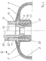
- the two neck areas of a composite pressure vessel 1 are shown in a half-sided longitudinal section. It consists of a plastic liner 2 produced by blow molding or rotation or thermoforming, which is reinforced by a fiber winding 3 wound from the outside.
- the reinforcing wrap consists of a fiber reinforcement, for example carbon, aramid, glass, boron, Al 2 O 3 fibers or mixtures (hybrid game), which are contained in a matrix of thermosets, e.g. B. epoxy or phenolic resins etc. or in thermoplastics such. B. PA12, PA6, PP etc. are embedded.
- the fiber composite material consisting of the above-mentioned fibers and polymers, is applied both in the axial and in the tangential direction of the container, i.e. the fiber reinforcement body (FRP) or the alignment of the fiber longitudinal axes have a small angle (0 °) in the case of axial wrapping in the cylindrical container part up to 60 °) with respect to the longitudinal axis of the container.
- the pole caps of the plastic liner 2 are wound evenly.
- the FRP is only deposited tangentially or in the circumferential direction of the cylindrical container part, consisting of both axial and tangential winding portions, but around the pole caps there is only one winding in the axial direction.
- the wall thickness proportions of tangential wrapping and axial wrapping depend on the outer diameter of the plastic liner 2, on the strength of the FRP, on the winding angles etc.
- the composite pressure vessel 1 has openings in the neck area, each with a Neck piece 4.5 are sealed.
- the neck piece 5 opposite the valve has in a known manner on a frustoconical collar 6, which in The edge area is very rounded and its inclination corresponds to the contour of the liner 2 is adjusted.
- the liner 2 in whole on the bottom 7 of the collar 6 to the system.
- To reinforce the Anchoring has the collar 6 axially extending bores 8 into which the liner 2 engages like a cone. A total of four bores are preferably arranged are arranged symmetrically over the circumference.
- the liner 2 is in this Area of the neck piece 5 closed, so that no sealing problem occurs here.
- an annular groove 9 into which the liner material intervenes positively is also be two or more grooves.
- the Recess 12 on the end face of the neck piece 5 serves to receive a Holding means, for example, a riding arbor tip. This is when winding the Container 1 required for inclusion in the rotating device of the winding system.
- the collar 6 of the neck piece 4 faces axially extending holes 8, preferably four, symmetrically over the circumference distributed.
- the additional anchoring also takes place via annular grooves 9, 10 in thread-free part 14 of the neck piece 4.
- the seal is designed differently of the end region 13 of the liner 2.
- a clamping ring 15 pressed onto the end region 13 of the liner 2.
- the clamping ring 15 has one Threaded portion 16 and a thread-free truncated cone Section 17.
- the latter section 17 corresponds to the bevel of the end area 13 of the liner 2.
- the clamping ring 15 can be rotated, it has an internal hexagon 18.
- a selected prestress is applied to the end region 13 of the liner 2.
- the arrangement described requires a cylindrical configuration of the Threaded portion 19 of the neck piece 4. This in turn means that also Valve 20 must also have a cylindrical thread.
- an annular groove 21 into which a seal 22 can be fixed.
- the critical one because of the tension Transition area 30 from the cylindrical jacket 11 to the neck area of the liner 2 is trained iso-tensoid.
- the continuously curved profile shown here is an approximation of a polygonal train consisting of many sections. The Such a curve is determined using many small iterative steps.
- FIG 3 shows a representation similar to Figure 1 another Embodiment of the valve connection, the same for the same parts Reference numerals have been chosen.
- the thread-free part 23 of the neck piece 25 extends inside the container. This has the advantage that the container length accordingly overall is getting shorter. It is necessary with this arrangement that the liner 2 around the thread-free part 23 is guided around.
- the other elements are the same as in Figure 1, so that there is no need to repeat the explanation.
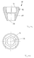
- FIGs 4a, b is on an enlarged scale and in a plan view of the End region 13 of the liner 2 (Fig. 1) cooperating clamping ring 15 shown.
- the hexagon socket 18 is used to insert a hexagon key, so that the Clamping ring 15 can be rotated accordingly. So that the rotation is sensitive can take place, the threaded portion 16 is provided with a fine thread.
- the diameter of the bore 28 arranged below the hexagon 18 is the Adjusted bore of the end portion 13 of the liner 2.
Landscapes
- Engineering & Computer Science (AREA)
- Mechanical Engineering (AREA)
- General Engineering & Computer Science (AREA)
- Filling Or Discharging Of Gas Storage Vessels (AREA)
Applications Claiming Priority (2)
| Application Number | Priority Date | Filing Date | Title |
|---|---|---|---|
| DE19631546 | 1996-07-24 | ||
| DE19631546A DE19631546C1 (de) | 1996-07-24 | 1996-07-24 | Composite-Druckbehälter zur Speicherung von gasförmigen Medien unter Druck mit einem Liner aus Kunststoff |
Publications (3)
| Publication Number | Publication Date |
|---|---|
| EP0821194A2 true EP0821194A2 (fr) | 1998-01-28 |
| EP0821194A3 EP0821194A3 (fr) | 1998-11-04 |
| EP0821194B1 EP0821194B1 (fr) | 2003-12-03 |
Family
ID=7801806
Family Applications (1)
| Application Number | Title | Priority Date | Filing Date |
|---|---|---|---|
| EP97250216A Expired - Lifetime EP0821194B1 (fr) | 1996-07-24 | 1997-07-21 | Récipient sous pression en matériau composite pour le stockage de fluides gazeux sous pression |
Country Status (5)
| Country | Link |
|---|---|
| EP (1) | EP0821194B1 (fr) |
| AT (1) | ATE255706T1 (fr) |
| DE (1) | DE19631546C1 (fr) |
| DK (1) | DK0821194T3 (fr) |
| ES (1) | ES2208820T3 (fr) |
Cited By (10)
| Publication number | Priority date | Publication date | Assignee | Title |
|---|---|---|---|---|
| WO2001051844A3 (fr) * | 2000-01-10 | 2002-02-07 | Ralph Funck | Recipient destine a contenir des substances liquides et/ou gazeuses sous pression, dote d'un recipient interne en plastique renforce par des plastiques eux-memes renforces par des fibres et procede de fabrication dudit recipient |
| EP1586807A2 (fr) | 2004-04-13 | 2005-10-19 | "Stako" sp. Jawna | Réservoir en matériau composite et procédé de fabrication |
| DE112004002795B4 (de) * | 2004-03-11 | 2010-02-04 | Korea Composite Research Co., Ltd. | Hochgradig gasdichter metallischer Düsenwulst für Hochdruck-Verbundstoffbehälter |
| DE102009049948A1 (de) * | 2009-10-19 | 2011-05-19 | Kautex Maschinenbau Gmbh | Druckbehälter |
| FR2962782A1 (fr) * | 2010-07-16 | 2012-01-20 | Djp | Embout de remplissage pour un reservoir de gaz. |
| DE102011056976A1 (de) * | 2011-12-23 | 2013-06-27 | Rehau Ag + Co | Vorrichtung zur Speicherung und Abgabe von flüssigen und / oder gasförmigen Medien unter Druck sowie Kraftstoffenergieumwandlungsvorrichtung und Verfahren zur Herstellung einer Vorrichtung zur Speicherung und Abgabe von flüssigen und / oder gasförmigen Medien unter Druck |
| CN106224759A (zh) * | 2016-09-05 | 2016-12-14 | 张晓冰 | 塑料内胆纤维缠绕储运瓶 |
| CN108131555A (zh) * | 2017-12-31 | 2018-06-08 | 亚普汽车部件股份有限公司 | 一种设置有密封结构的高压复合容器 |
| CN116100841A (zh) * | 2023-01-13 | 2023-05-12 | 江苏集萃复合材料装备研究所有限公司 | 一种用于高压氢气瓶的制备方法 |
| US12618529B2 (en) * | 2023-12-13 | 2026-05-05 | Hyundai Motor Company; | Nozzle for pressure vessel and pressure vessel including the same |
Families Citing this family (28)
| Publication number | Priority date | Publication date | Assignee | Title |
|---|---|---|---|---|
| DE19751411C1 (de) * | 1997-11-14 | 1999-01-14 | Mannesmann Ag | Composite-Druckbehälter zur Speicherung von gasförmigen Medien unter Druck mit einem Liner aus Kunststoff |
| DE102006001052A1 (de) * | 2006-01-07 | 2007-09-06 | Xperion Gmbh | Druckbehälter zur Speicherung von flüssigen oder gasförmigen Medien |
| DE102006006902B4 (de) * | 2006-02-09 | 2008-02-21 | Gräfenthaler Kunststofftechnik GmbH | Druckbehälter aus Kunststoff und Verfahren zu seiner Herstellung |
| JP4599380B2 (ja) * | 2007-09-04 | 2010-12-15 | 八千代工業株式会社 | 高圧容器のシール構造 |
| PL210271B1 (pl) | 2008-04-25 | 2011-12-30 | Krzysztof Moskwa | Gaśnica płynowa |
| US8523002B2 (en) * | 2010-02-26 | 2013-09-03 | GM Global Technology Operations LLC | Embedded reinforcement sleeve for a pressure vessel |
| CN102906484B (zh) * | 2010-05-19 | 2014-06-11 | 八千代工业株式会社 | 压力容器的口承部件与吹塑杆的卡合构造、具有该卡合构造的压力容器的口承构造及压力容器的制造方法 |
| CN101832389B (zh) * | 2010-06-02 | 2012-10-10 | 刘强 | 纤维增强复合材料压力瓶 |
| WO2012074373A1 (fr) * | 2010-11-30 | 2012-06-07 | Advanced Lightweight Engineering B.V. | Cuve |
| WO2012131724A2 (fr) * | 2011-03-31 | 2012-10-04 | Genex Science And Technologies Pvt. Ltd. | Bouteilles sous pression en matériau composite carénées à bossage métallique amélioré |
| DE202012101004U1 (de) | 2012-03-21 | 2013-06-24 | Rehau Ag + Co | Vorrichtung zur Speicherung und Abgabe von flüssigen und/oder gasförmigen Medien unter Druck sowie Kraftstoffenergieumwandlungsvorrichtung |
| DE102011052490A1 (de) | 2011-08-08 | 2013-02-14 | Rehau Ag + Co. | Vorrichtung zur Speicherung und Abgabe von flüssigen und/oder gasförmigen Medien unter Druck sowie Kraftstoffenergieumwandlungsvorrichtung und Verfahren zur Montage einer Vorrichtung zur Speicherung und Abgabe von flüssigen und/oder gasförmigen Medien unter Druck |
| WO2013020668A1 (fr) | 2011-08-08 | 2013-02-14 | Rehau Ag + Co | Dispositif pour l'accumulation et la distribution de milieux liquides et/ou gazeux sous pression, ainsi que dispositif de transformation d'énergie de carburant et procédé pour le montage d'un dispositif pour l'accumulation et la distribution de milieux liquides et/ou gazeux sous pression |
| DE102011116553A1 (de) | 2011-10-21 | 2013-04-25 | Kautex Textron Gmbh & Co. Kg | Verfahren zur Herstellung eines Verbund-Druckbehälters sowie Verbund-Druckbehälter |
| DE102011120041A1 (de) | 2011-12-02 | 2013-06-06 | Volkswagen Aktiengesellschaft | Druckbehälter zur Speicherung von fluiden Medien und Verfahren zur Herstellung eines derartigen Druckbehälters sowie Anschlussstück für einen Druckbehälter |
| CN102865455B (zh) * | 2012-09-14 | 2014-07-23 | 湖北三江航天江北机械工程有限公司 | 高温高压绝热复合气瓶及其制造方法 |
| EP2929231A1 (fr) * | 2012-12-05 | 2015-10-14 | Blue Wave Co S.A. | Récipient de pression ayant un bossage composite ayant un raccord métallique soudable |
| DE102013101425A1 (de) * | 2013-02-08 | 2014-08-28 | Rehau Ag + Co | Vorrichtung zur Speicherung und Abgabe von flüssigen und / oder gasförmigen Medien unter Druck sowie Kraftstoffenergieumwandlungsvorrichtung und Verfahren zur Montage einer Vorrichtung zur Speicherung und Abgabe von flüssigen und/oder gasförmigen Medien unter Druck |
| TR201302927A2 (tr) * | 2013-03-11 | 2014-09-22 | Tofas Tuerk Otomobil Fabrikasi Anonim Sirketi | Boğaz yapısı. |
| DE102014207069B4 (de) | 2014-04-11 | 2025-07-10 | Bayerische Motoren Werke Aktiengesellschaft | Anschlusselement für einen Drucktank sowie Drucktank |
| USD746942S1 (en) | 2014-10-21 | 2016-01-05 | Advanced Lightweight Engineering B.V. | Low weight pressure vessel |
| DE102014116951A1 (de) * | 2014-11-19 | 2016-05-19 | Thyssenkrupp Ag | Druckbehälter und Verfahren zum Fertigen eines Druckbehälters |
| JP6356172B2 (ja) * | 2016-03-15 | 2018-07-11 | 本田技研工業株式会社 | 高圧タンク |
| US10487983B2 (en) * | 2016-08-04 | 2019-11-26 | The Boeing Company | Composite joint |
| US11333301B2 (en) | 2017-05-15 | 2022-05-17 | Advanced Lightweight Engineering B.V. | Pressure vessel for the storage of pressurized fluids and vehicle comprising such a pressure vessel |
| DE202020000706U1 (de) | 2020-02-20 | 2020-05-11 | Emano Kunststofftechnik Gmbh | Druckbehälter |
| DE102020001135B3 (de) | 2020-02-20 | 2021-08-26 | Emano Kunststofftechnik Gmbh | Druckbehälter und Verfahren zur Herstellung eines Druckbehälters |
| DE102022203607A1 (de) | 2022-04-11 | 2023-10-12 | Robert Bosch Gesellschaft mit beschränkter Haftung | Speichervorrichtung, Brennstoffzellenanordnung, Wasserstoff-Verbrennungsmotorsystem und wasserstoffbetriebenes Fahrzeug |
Family Cites Families (7)
| Publication number | Priority date | Publication date | Assignee | Title |
|---|---|---|---|---|
| US3508677A (en) * | 1968-08-20 | 1970-04-28 | Whittaker Corp | Vessel for storing high-pressure gases |
| DE2152123C3 (de) * | 1971-10-20 | 1974-07-11 | Elektrische Licht- Und Kraftanlagen Ag, 3579 Frielendorf | Druckbehälter |
| FR2193953B1 (fr) * | 1972-07-27 | 1975-09-05 | Air Liquide | |
| BE902543A (nl) * | 1985-05-30 | 1985-09-16 | Duktrad Internat | Halsafsluitring voor kunststof druktanks. |
| DE69206114T2 (de) * | 1992-01-10 | 1996-04-18 | Technical Products Group Inc | Polstück für ein fasergewickeltes Druckgefäss. |
| WO1994023241A1 (fr) * | 1993-04-07 | 1994-10-13 | Edo Canada Ltd. | Systeme perfectionne de fixation de l'obturateur d'un recipient sous pression pour fluides a la cuve interne de celui-ci |
| US5526994A (en) * | 1994-12-01 | 1996-06-18 | Essef Corporation | Filament-wound isotensoid pressure vessels having geodesic domes |
-
1996
- 1996-07-24 DE DE19631546A patent/DE19631546C1/de not_active Expired - Fee Related
-
1997
- 1997-07-21 EP EP97250216A patent/EP0821194B1/fr not_active Expired - Lifetime
- 1997-07-21 ES ES97250216T patent/ES2208820T3/es not_active Expired - Lifetime
- 1997-07-21 DK DK97250216T patent/DK0821194T3/da active
- 1997-07-21 AT AT97250216T patent/ATE255706T1/de not_active IP Right Cessation
Cited By (15)
| Publication number | Priority date | Publication date | Assignee | Title |
|---|---|---|---|---|
| WO2001051844A3 (fr) * | 2000-01-10 | 2002-02-07 | Ralph Funck | Recipient destine a contenir des substances liquides et/ou gazeuses sous pression, dote d'un recipient interne en plastique renforce par des plastiques eux-memes renforces par des fibres et procede de fabrication dudit recipient |
| US7032767B2 (en) | 2000-01-10 | 2006-04-25 | Ralph Funck | Pressurized container for storing pressurized liquid and/or gaseous media, consisting of a plastic core container which is reinforced with fibre-reinforced plastics and a method for producing the same |
| DE112004002795B4 (de) * | 2004-03-11 | 2010-02-04 | Korea Composite Research Co., Ltd. | Hochgradig gasdichter metallischer Düsenwulst für Hochdruck-Verbundstoffbehälter |
| EP1586807A2 (fr) | 2004-04-13 | 2005-10-19 | "Stako" sp. Jawna | Réservoir en matériau composite et procédé de fabrication |
| DE102009049948B4 (de) * | 2009-10-19 | 2012-02-02 | Kautex Maschinenbau Gmbh | Druckbehälter |
| DE102009049948A1 (de) * | 2009-10-19 | 2011-05-19 | Kautex Maschinenbau Gmbh | Druckbehälter |
| US8505762B2 (en) | 2009-10-19 | 2013-08-13 | Kautex Maschinenbau Gmbh | Vessel neck construction of a pressure vessel |
| FR2962782A1 (fr) * | 2010-07-16 | 2012-01-20 | Djp | Embout de remplissage pour un reservoir de gaz. |
| DE102011056976A1 (de) * | 2011-12-23 | 2013-06-27 | Rehau Ag + Co | Vorrichtung zur Speicherung und Abgabe von flüssigen und / oder gasförmigen Medien unter Druck sowie Kraftstoffenergieumwandlungsvorrichtung und Verfahren zur Herstellung einer Vorrichtung zur Speicherung und Abgabe von flüssigen und / oder gasförmigen Medien unter Druck |
| CN106224759A (zh) * | 2016-09-05 | 2016-12-14 | 张晓冰 | 塑料内胆纤维缠绕储运瓶 |
| CN108131555A (zh) * | 2017-12-31 | 2018-06-08 | 亚普汽车部件股份有限公司 | 一种设置有密封结构的高压复合容器 |
| CN108131555B (zh) * | 2017-12-31 | 2023-07-25 | 亚普汽车部件股份有限公司 | 一种设置有密封结构的高压复合容器 |
| CN116100841A (zh) * | 2023-01-13 | 2023-05-12 | 江苏集萃复合材料装备研究所有限公司 | 一种用于高压氢气瓶的制备方法 |
| CN116100841B (zh) * | 2023-01-13 | 2024-01-26 | 江苏集萃复合材料装备研究所有限公司 | 一种用于高压氢气瓶的制备方法 |
| US12618529B2 (en) * | 2023-12-13 | 2026-05-05 | Hyundai Motor Company; | Nozzle for pressure vessel and pressure vessel including the same |
Also Published As
| Publication number | Publication date |
|---|---|
| ES2208820T3 (es) | 2004-06-16 |
| EP0821194B1 (fr) | 2003-12-03 |
| DK0821194T3 (da) | 2004-03-08 |
| DE19631546C1 (de) | 1997-11-13 |
| EP0821194A3 (fr) | 1998-11-04 |
| ATE255706T1 (de) | 2003-12-15 |
Similar Documents
| Publication | Publication Date | Title |
|---|---|---|
| EP0821194B1 (fr) | Récipient sous pression en matériau composite pour le stockage de fluides gazeux sous pression | |
| EP1029195B1 (fr) | Reservoir a pression composite muni d'un revetement en plastique, servant a stocker des milieux gazeux sous pression | |
| EP0753700B1 (fr) | Récipient de pression en matériau composite pour le stockage de fluides gazeux sous pression pourvu d'un revêtement en matière plastique et méthode pour la construction du récipient | |
| DE102010018700B4 (de) | Druckbehälter | |
| DE2152123C3 (de) | Druckbehälter | |
| EP3374685B1 (fr) | Réservoir sous pression antistatique amélioré | |
| EP2718570B1 (fr) | Récipient sous pression | |
| EP2491294A1 (fr) | Constitution de col de récipient d'un récipient sous pression | |
| WO2007085276A1 (fr) | Réservoir sous pression | |
| WO2001051844A2 (fr) | Recipient destine a contenir des substances liquides et/ou gazeuses sous pression, dote d'un recipient interne en plastique renforce par des plastiques eux-memes renforces par des fibres et procede de fabrication dudit recipient | |
| DE102020134633A1 (de) | Drucktank für gasbetriebenes Fahrzeug | |
| DE102018009829B4 (de) | Druckbehälter und Verfahren zur Herstellung des Druckbehälters | |
| EP3869080A1 (fr) | Récipient sous pression et procédé de fabrication d'un récipient sous pression | |
| DE102014013249B4 (de) | Druckbehälter | |
| DE2248589C3 (de) | Elektrisch isolierende Rohrkupplung | |
| DE102021107165B4 (de) | Endboss-Abdichtung | |
| WO2022135872A1 (fr) | Bouchon pour réservoir sous pression et réservoir sous pression pour véhicule à gaz | |
| DE102008033874B4 (de) | Druckgastank | |
| DE3642998C1 (de) | Tiefgezogener Drehverschluss aus Aluminium fuer unter Innendruck stehende Glasflaschen sowie Tiefziehvorrichtung fuer einen Verschliesskopf zum Herstellen derartiger Drehverschluesse | |
| EP0237046B1 (fr) | Garniture de raccord pour exerçer axialement des forces de traction et de compression sur des tiges en matériau composite renforcé par des fibres | |
| DE19651659C1 (de) | Dichtungselement für eine Wanddurchführung | |
| DE202018005823U1 (de) | Druckbehälter | |
| WO1999057032A1 (fr) | Bouchon filete pour bouteilles | |
| DE8913050U1 (de) | Druckbehälter zum Speichern von unter hohem Druck stehenden giftigen Gasen | |
| DE2715773A1 (de) | Pruefverschluss zum einseitigen und/oder zweiseitigen, druckdichten verschliessen von zu pruefenden hohlzylinderabschnitten |
Legal Events
| Date | Code | Title | Description |
|---|---|---|---|
| PUAI | Public reference made under article 153(3) epc to a published international application that has entered the european phase |
Free format text: ORIGINAL CODE: 0009012 |
|
| AK | Designated contracting states |
Kind code of ref document: A2 Designated state(s): AT BE CH DE DK ES FI FR GB IT LI NL SE |
|
| PUAL | Search report despatched |
Free format text: ORIGINAL CODE: 0009013 |
|
| AK | Designated contracting states |
Kind code of ref document: A3 Designated state(s): AT BE CH DE DK ES FI FR GB GR IE IT LI LU MC NL PT SE |
|
| 17P | Request for examination filed |
Effective date: 19981002 |
|
| AKX | Designation fees paid |
Free format text: AT BE CH DE DK ES FI FR GB IT LI NL SE |
|
| GRAH | Despatch of communication of intention to grant a patent |
Free format text: ORIGINAL CODE: EPIDOS IGRA |
|
| GRAS | Grant fee paid |
Free format text: ORIGINAL CODE: EPIDOSNIGR3 |
|
| GRAA | (expected) grant |
Free format text: ORIGINAL CODE: 0009210 |
|
| RAP1 | Party data changed (applicant data changed or rights of an application transferred) |
Owner name: MCS INTERNATIONAL GMBH |
|
| RBV | Designated contracting states (corrected) |
Designated state(s): AT BE CH DK ES FI FR GB IT LI NL SE |
|
| AK | Designated contracting states |
Kind code of ref document: B1 Designated state(s): AT BE CH DK ES FI FR GB IT LI NL SE |
|
| REG | Reference to a national code |
Ref country code: GB Ref legal event code: FG4D Free format text: NOT ENGLISH |
|
| REG | Reference to a national code |
Ref country code: CH Ref legal event code: EP |
|
| REG | Reference to a national code |
Ref country code: SE Ref legal event code: TRGR |
|
| REG | Reference to a national code |
Ref country code: DE Ref legal event code: 8566 |
|
| REG | Reference to a national code |
Ref country code: CH Ref legal event code: NV Representative=s name: E. BLUM & CO. PATENTANWAELTE |
|
| GBT | Gb: translation of ep patent filed (gb section 77(6)(a)/1977) |
Effective date: 20040114 |
|
| REG | Reference to a national code |
Ref country code: DK Ref legal event code: T3 |
|
| ET | Fr: translation filed | ||
| REG | Reference to a national code |
Ref country code: ES Ref legal event code: FG2A Ref document number: 2208820 Country of ref document: ES Kind code of ref document: T3 |
|
| PLBE | No opposition filed within time limit |
Free format text: ORIGINAL CODE: 0009261 |
|
| STAA | Information on the status of an ep patent application or granted ep patent |
Free format text: STATUS: NO OPPOSITION FILED WITHIN TIME LIMIT |
|
| 26N | No opposition filed |
Effective date: 20040906 |
|
| PGFP | Annual fee paid to national office [announced via postgrant information from national office to epo] |
Ref country code: DK Payment date: 20070713 Year of fee payment: 11 |
|
| PGFP | Annual fee paid to national office [announced via postgrant information from national office to epo] |
Ref country code: ES Payment date: 20070727 Year of fee payment: 11 |
|
| REG | Reference to a national code |
Ref country code: CH Ref legal event code: PFA Owner name: MCS INTERNATIONAL GMBH Free format text: MCS INTERNATIONAL GMBH#KARLSTRASSE 23-25#46535 DINSLAKEN (DE) -TRANSFER TO- MCS INTERNATIONAL GMBH#KARLSTRASSE 23-25#46535 DINSLAKEN (DE) |
|
| PGFP | Annual fee paid to national office [announced via postgrant information from national office to epo] |
Ref country code: FI Payment date: 20070713 Year of fee payment: 11 Ref country code: CH Payment date: 20070713 Year of fee payment: 11 Ref country code: AT Payment date: 20070716 Year of fee payment: 11 |
|
| PGFP | Annual fee paid to national office [announced via postgrant information from national office to epo] |
Ref country code: GB Payment date: 20070720 Year of fee payment: 11 |
|
| PGFP | Annual fee paid to national office [announced via postgrant information from national office to epo] |
Ref country code: SE Payment date: 20070712 Year of fee payment: 11 Ref country code: NL Payment date: 20070716 Year of fee payment: 11 Ref country code: IT Payment date: 20070723 Year of fee payment: 11 Ref country code: BE Payment date: 20070802 Year of fee payment: 11 |
|
| PGFP | Annual fee paid to national office [announced via postgrant information from national office to epo] |
Ref country code: FR Payment date: 20070710 Year of fee payment: 11 |
|
| REG | Reference to a national code |
Ref country code: CH Ref legal event code: PL |
|
| REG | Reference to a national code |
Ref country code: DK Ref legal event code: EBP |
|
| EUG | Se: european patent has lapsed | ||
| GBPC | Gb: european patent ceased through non-payment of renewal fee |
Effective date: 20080721 |
|
| NLV4 | Nl: lapsed or anulled due to non-payment of the annual fee |
Effective date: 20090201 |
|
| PG25 | Lapsed in a contracting state [announced via postgrant information from national office to epo] |
Ref country code: AT Free format text: LAPSE BECAUSE OF NON-PAYMENT OF DUE FEES Effective date: 20080721 |
|
| REG | Reference to a national code |
Ref country code: FR Ref legal event code: ST Effective date: 20090331 |
|
| PG25 | Lapsed in a contracting state [announced via postgrant information from national office to epo] |
Ref country code: NL Free format text: LAPSE BECAUSE OF NON-PAYMENT OF DUE FEES Effective date: 20090201 Ref country code: FI Free format text: LAPSE BECAUSE OF NON-PAYMENT OF DUE FEES Effective date: 20080721 |
|
| PG25 | Lapsed in a contracting state [announced via postgrant information from national office to epo] |
Ref country code: LI Free format text: LAPSE BECAUSE OF NON-PAYMENT OF DUE FEES Effective date: 20080731 Ref country code: GB Free format text: LAPSE BECAUSE OF NON-PAYMENT OF DUE FEES Effective date: 20080721 Ref country code: CH Free format text: LAPSE BECAUSE OF NON-PAYMENT OF DUE FEES Effective date: 20080731 |
|
| PG25 | Lapsed in a contracting state [announced via postgrant information from national office to epo] |
Ref country code: DK Free format text: LAPSE BECAUSE OF NON-PAYMENT OF DUE FEES Effective date: 20080731 |
|
| PG25 | Lapsed in a contracting state [announced via postgrant information from national office to epo] |
Ref country code: IT Free format text: LAPSE BECAUSE OF NON-PAYMENT OF DUE FEES Effective date: 20080721 Ref country code: FR Free format text: LAPSE BECAUSE OF NON-PAYMENT OF DUE FEES Effective date: 20080731 |
|
| REG | Reference to a national code |
Ref country code: ES Ref legal event code: FD2A Effective date: 20080722 |
|
| PG25 | Lapsed in a contracting state [announced via postgrant information from national office to epo] |
Ref country code: ES Free format text: LAPSE BECAUSE OF NON-PAYMENT OF DUE FEES Effective date: 20080722 |
|
| PG25 | Lapsed in a contracting state [announced via postgrant information from national office to epo] |
Ref country code: SE Free format text: LAPSE BECAUSE OF NON-PAYMENT OF DUE FEES Effective date: 20080722 Ref country code: BE Free format text: LAPSE BECAUSE OF NON-PAYMENT OF DUE FEES Effective date: 20080731 |