EP0821356A2 - Dispositif d'entraínement de disque et méthode pour en fixer la vitesse de rotation - Google Patents
Dispositif d'entraínement de disque et méthode pour en fixer la vitesse de rotation Download PDFInfo
- Publication number
- EP0821356A2 EP0821356A2 EP97112759A EP97112759A EP0821356A2 EP 0821356 A2 EP0821356 A2 EP 0821356A2 EP 97112759 A EP97112759 A EP 97112759A EP 97112759 A EP97112759 A EP 97112759A EP 0821356 A2 EP0821356 A2 EP 0821356A2
- Authority
- EP
- European Patent Office
- Prior art keywords
- disk
- track
- recording medium
- shaped recording
- head
- Prior art date
- Legal status (The legal status is an assumption and is not a legal conclusion. Google has not performed a legal analysis and makes no representation as to the accuracy of the status listed.)
- Granted
Links
Images







Classifications
-
- G—PHYSICS
- G11—INFORMATION STORAGE
- G11B—INFORMATION STORAGE BASED ON RELATIVE MOVEMENT BETWEEN RECORD CARRIER AND TRANSDUCER
- G11B19/00—Driving, starting, stopping record carriers not specifically of filamentary or web form, or of supports therefor; Control thereof; Control of operating function ; Driving both disc and head
- G11B19/20—Driving; Starting; Stopping; Control thereof
- G11B19/28—Speed controlling, regulating, or indicating
-
- G—PHYSICS
- G11—INFORMATION STORAGE
- G11B—INFORMATION STORAGE BASED ON RELATIVE MOVEMENT BETWEEN RECORD CARRIER AND TRANSDUCER
- G11B19/00—Driving, starting, stopping record carriers not specifically of filamentary or web form, or of supports therefor; Control thereof; Control of operating function ; Driving both disc and head
- G11B19/02—Control of operating function, e.g. switching from recording to reproducing
- G11B19/04—Arrangements for preventing, inhibiting, or warning against double recording on the same blank or against other recording or reproducing malfunctions
- G11B19/041—Detection or prevention of read or write errors
- G11B19/042—Detection or prevention of read or write errors due to external shock or vibration
-
- G—PHYSICS
- G11—INFORMATION STORAGE
- G11B—INFORMATION STORAGE BASED ON RELATIVE MOVEMENT BETWEEN RECORD CARRIER AND TRANSDUCER
- G11B19/00—Driving, starting, stopping record carriers not specifically of filamentary or web form, or of supports therefor; Control thereof; Control of operating function ; Driving both disc and head
- G11B19/02—Control of operating function, e.g. switching from recording to reproducing
- G11B19/12—Control of operating function, e.g. switching from recording to reproducing by sensing distinguishing features of or on records, e.g. diameter end mark
- G11B19/128—Control of operating function, e.g. switching from recording to reproducing by sensing distinguishing features of or on records, e.g. diameter end mark involving the detection of track pitch or recording density
-
- G—PHYSICS
- G11—INFORMATION STORAGE
- G11B—INFORMATION STORAGE BASED ON RELATIVE MOVEMENT BETWEEN RECORD CARRIER AND TRANSDUCER
- G11B19/00—Driving, starting, stopping record carriers not specifically of filamentary or web form, or of supports therefor; Control thereof; Control of operating function ; Driving both disc and head
- G11B19/20—Driving; Starting; Stopping; Control thereof
- G11B19/2009—Turntables, hubs and motors for disk drives; Mounting of motors in the drive
-
- G—PHYSICS
- G11—INFORMATION STORAGE
- G11B—INFORMATION STORAGE BASED ON RELATIVE MOVEMENT BETWEEN RECORD CARRIER AND TRANSDUCER
- G11B19/00—Driving, starting, stopping record carriers not specifically of filamentary or web form, or of supports therefor; Control thereof; Control of operating function ; Driving both disc and head
- G11B19/20—Driving; Starting; Stopping; Control thereof
- G11B19/26—Speed-changing arrangements; Reversing arrangements; Drive-transfer means therefor
-
- G—PHYSICS
- G11—INFORMATION STORAGE
- G11B—INFORMATION STORAGE BASED ON RELATIVE MOVEMENT BETWEEN RECORD CARRIER AND TRANSDUCER
- G11B2220/00—Record carriers by type
- G11B2220/20—Disc-shaped record carriers
- G11B2220/25—Disc-shaped record carriers characterised in that the disc is based on a specific recording technology
- G11B2220/2537—Optical discs
- G11B2220/2545—CDs
Definitions
- This invention relates to a disk drive device suitable for use in a CD-ROM (Compact Disk as Read Only Memory) or the like, for example and a method of setting a rotational speed of the disk drive device.
- This invention relates specifically to a disk drive device for determining or distinguishing that a disk-shaped recording medium is either an eccentric disk or an unbalance disk in a state in which the disk-shaped recording medium is being rotated at a predetermined speed.
- a rotational speed of the disk drive device is reduced to thereby lessen vibrations transferred to the outside and to maintain high performance against external vibrations and impact and satisfactorily perform a recording and reproducing operations.
- This invention also relates to a disk drive device or the like capable of, when it is determined in a state in which a disk-shaped recording medium is being rotated at a predetermined speed, that the disk-shaped recording medium is not either an eccentric disk or an unbalance disk, increasing its rotational speed to thereby read data at high speed.
- This invention relates to a disk drive device or the like of a type wherein when it is distinguished in a state in which a disk-shaped recording medium is being rotated at a predetermined speed, that an external vibration or impact of a predetermined level or more has occurred, its rotational speed is reduced to thereby lessen the influence of the external vibration or impact of the predetermined level or more on recording and reproducing operations.
- Fig. 20 shows a principal portion of a related CD-ROM drive device.
- a pair of pin support holes (not shown) is defined in both side plates 50a of a fixed case.
- a pair of pins 53 of a base unit holder 52 is inserted into their corresponding pin support holes.
- An elevation pin 54 is provided on side opposite to the provision of the pair of pins 53 of the base unit holder 52.
- the elevation pin 54 is displaced in upward and downward directions by a base unit elevation mechanism (not shown) so that the one-end side of the base unit holder 52 moves up and down.
- Bosses 55 are placed in three points of the base unit holder 52. Threaded holes 56 are defined in their corresponding bosses 55.
- a base unit 57 has a base plate 58 to which an optical pick-up unit 59 for reproducing data from a disk, a disk rotating unit 60 having a spindle motor for rotating the disk, etc. have been attached.
- Mounting holes 61 are respectively provided at three points of the base plate 58.
- the base unit 57 is mounted to the base unit holder 52 by using mounting vises 62 insulator 63 used as damping members composed of rubber.
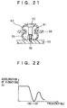
- Fig. 21 shows a mounting portion of the base unit 57 in developed form.
- the insulators 63 are mounted in their corresponding mounting holes 61 defined in the base plate 58 of the base unit 57.
- the mounting vises 62 inserted into holes of the insulators 63 are threadedly inserted into threaded holes 56 of the bosses 55 of the base unit holder 52.
- an external vibration or impact is transmitted to the base unit holder 52 through the fixed case 50 without attenuation so far.
- the vibration transmitted to the base unit holder 52 is transmitted to the base unit 57 through the insulators 63 for providing damping action.
- the external vibration and impact is attenuated and applied to the base unit 57, so that the bad influence of the vibration and impact thereon is lessened.
- An external vibration characteristic of the base unit 57 has a resonance point at a range of 100Hz to 120Hz, for example, as shown in Fig. 22.
- the number of revolutions of the disk ranges from 200rpm to 500rpm (3.3 to 8.3Hz) at a standard speed, ranges from 800rpm to 2000rpm (13 to 33Hz) at a quadruple speed, ranges from 1200rpm to 3000rpm (20 to 50Hz) at a sextuple speed, ranges from 1600rpm to 4000rpm (27 to 67Hz) at an octuple speed, and ranges from 2400rpm to 6000rpm (40 to 100Hz) at a dodecuple speed.
- Fig. 23 shows a transmission characteristic of each insulator 63.
- a resonance point f0 of the insulator 63 can be set to a range of 25 to 130Hz. As the resonance f0 is made great, a Q value is reduced so that an attenuatable frequency is shifted to a high frequency.
- the resonance point of the insulator 63 is set so as to attenuate 100 to 120Hz corresponding to the resonance point of the vibration characteristic of the base unit 57 and escape from a frequency corresponding to the number of revolutions of the disk, which is to be used.
- the number of revolutions to be used increases as in the case of the sextuple speed, octuple speed, ..., it is difficult to satisfy the two.
- the resonance point f0 of the insulator 63 was set so as to be higher than the maximum number of revolutions of the disk and to satisfy escaping from the frequency corresponding to the number of revolutions of the disk, which is to be used. Therefore, although the problem about the aforementioned self-induced vibration can be lessened, the range of 100 to 120Hz corresponding to the resonance point of the vibration characteristic of the base unit 57 cannot be attenuated sufficiently, thus resulting in significant reduction in the performance against an external vibration and impact.
- an object of the present invention is to lessen vibrations transferred to the outside, maintain high performance against an external vibration and impact and satisfactorily perform recording and reproducing operations.
- Another object of the present invention is to lessen the influence of an external vibration or impact of a predetermined level or more on recording and reproducing operations.
- a disk drive device wherein a base unit provided with a disk rotating unit having a spindle motor for rotating a disk-shaped recording medium and with a head for performing at least one of recording and reproducing data into and from the disk-shaped recording medium, is mounted to a base unit holder through a damping member, comprising: rotational speed control means for controlling the rotation of the spindle motor to thereby control a rotational speed of the disk-shaped recording medium to a set value; disk distinguishing means for determining, in a state in which the disk-shaped recording medium is being rotated, whether the disk-shaped recording medium is an eccentric disk or an unbalance disk; and rotational speed setting means for, when the disk distinguishing means has determined the disk-shaped recording medium as the eccentric disk or the unbalance disk, changing the set value to a second rotational speed slower than the first rotational speed in a state in which the disk-shaped recording medium is being rotated at a first rotational speed.
- a method of setting a rotational speed of a disk drive device wherein a base unit provided with a disk rotating unit having a spindle motor for rotating a disk-shaped recording medium and with a head for performing at least one of recording and reproducing data into and from the disk-shaped recording medium, is mounted to a base unit holder through a damping member, comprising the following steps: a first step for controlling the disk rotating unit so as to rotate the disk-shaped recording medium at a first rotational speed; a second step for distinguishing in a state in which the disk-shaped recording medium is being rotated at the first rotational speed, whether the disk-shaped recording medium is either an eccentric disk or an unbalance disk; and a third step for setting the rotational speed of the disk-shaped recording medium to a second rotational speed slower than the first rotational speed when the disk-shaped recording medium is either the eccentric disk or the unbalance disk.
- the head records data into or reproduces it from the disk-shaped recording medium rotated and driven by the spindle motor.
- the rotational speed of the disk-shaped recording medium is controlled to set values such as a standard speed, a quadruple speed, a sextuple speed, ....
- the disk-shaped recording medium is either the eccentric disk or the unbalance disk, is distinguished by utilizing a point of view in which for example, when the disk-shaped recording medium is either the eccentric disk or the unbalance disk, a tracking error signal and a control signal for the spindle motor are different in level range from the case in which the disk-shaped recording medium is a general disk.
- the rotational speed of the disk-shaped recording medium is set slow.
- the disk-shaped recording medium is determined to be either the eccentric disk or the unbalance disk in a state in which the disk-shaped recording medium is being rotated at the sextuple speed, the disk-shaped recording medium is set to the quadruple speed.
- the rotational speed of the disk-shaped recording medium is set fast.
- the disk-shaped recording medium is determined not to be either the eccentric disk or the unbalance disk in a state of being rotated at the quadruple speed
- the disk-shaped recording medium is set to the sextuple speed.
- the rotational speed of the disk-shaped recording medium may be set so as to increase from the quadruple speed to the octuple speed. If the detected reset playback speed is an unpleasant-feeling free speed if it is a reset speed, then an arbitrary playback speed can be selected within its range.
- a disk drive device which includes a disk rotating unit having a spindle motor for rotating a disk-shaped recording medium, and a head for performing at least one of recording and reproducing data into and from the disk-shaped recording medium, comprising: rotational speed control means for controlling the rotation of the spindle motor to thereby control a rotational speed of the disk-shaped recording medium to a set value; vibration and impact distinguishing means for distinguishing whether an external vibration or impact of a predetermined level or more occurs, in a state in which the disk-shaped recording medium is being rotated; and rotational speed setting means for, when the vibration and impact distinguishing means has determined the occurrence of the external vibration or impact of the predetermined level or more in a state in which the rotational speed of the disk-shaped recording medium is at a first rotational speed, changing the set value to a second rotational speed slower than the first rotational speed.
- a method of setting a rotational speed of a disk drive device which includes a disk rotating unit having a spindle motor for rotating a disk-shaped recording medium, and a head for performing at least one of recording and reproducing data into and from the dish-shaped recording medium, comprising the following steps: a first step for controlling the disk rotating unit so as to rotate the disk-shaped recording medium at a first rotational speed; a second step for distinguishing in a state in which the disk-shaped recording medium is being rotated at the first rotational speed, whether an external vibration or impact of a predetermined level or more occurs; and a third step for setting the rotational speed of the disk-shaped recording medium to a second rotational speed slower than the first rotational speed when the external vibration or impact of the predetermined level or more occurs.
- the head records data into or reproduces it from the disk-shaped recording medium rotated and driven by the spindle motor.
- the rotational speed of the disk-shaped recording medium is controlled to set values such as a standard speed, a quadruple speed, a sextuple speed, ....
- the disk-shaped recording medium is being rotated, whether or not the external vibration or impact of the predetermined level occurs, is identified or distinguished. Whether or not the external vibration or impact of the predetermined level or more occurs, is distinguished by utilizing a change in the level range of each of a tracking error signal and a control signal for the spindle motor when, for example, the external vibration or impact of the predetermined level or more occurs.
- the rotational speed of the disk-shaped recording medium is set slow.
- the disk-shaped recording medium is set to the quadruple speed.
- the rotational speed can be also controlled to a rotational speed (sextuple or octuple speed) faster than the slow rotational speed (standard rotational speed to be detected, e.g., quadruple speed) when the disk-shaped recording medium is found not to be either an eccentric disk or an unbalance disk.
- Fig. 1 shows a CD-ROM drive device 100 as one embodiment.
- the CD-ROM drive device 100 has a spindle motor 102 for rotating and driving a disk 101 at a predetermined linear velocity.
- the CD-ROM drive device 100 is capable of playing back or reproducing data at a standard speed, a quadruple speed and a sextuple speed.
- the disk 101 is driven so as to rotate at 200 rpm (outer periphery) to 500 rpm (inner periphery) upon data reproduction at the standard speed.
- the disk 101 Upon data reproduction at the quadruple speed, the disk 101 is driven so as to rotate at 800 rpm (outer periphery) to 2000 rpm (inner periphery).
- the disk 101 is driven so as to rotate at 200 rpm (outer periphery) to 3000 rpm (inner periphery) upon data reproduction at the sextuple speed.
- the CD-ROM drive device 100 has an optical pick-up unit 103 used as a head for reproducing data from the disk 101, and a RF amplifier unit 104 for electrically processing signals outputted from a plurality of optical detectors constituting the optical pick-up unit 103 to obtain a playback or reproduce RF signal SRF, a tracking error signal ET and a focus error signal EF.
- the signals outputted from the plurality of optical detectors are supplied to the RF amplifier unit 104.
- the RF amplifier unit 104 produces the tracking error signal ET by a three-spot method, for example, and produces the focus error signal EF by an astigma method.
- the CD-ROM drive device 100 has a RF signal processing circuit 105 for performing a process such as waveform equalization on the playback RF signal SRF outputted from the RF amplifier 104, and a CD decoder 106 for effecting an EFM (Eight to fourteen Modulation) demodulating process and an error-correcting process by CIRC (Cross Interleave Reed-Solomon Code) on a signal outputted from the RF signal processing circuit 105.
- EFM Eight to fourteen Modulation
- CIRC Cross Interleave Reed-Solomon Code
- the CD-ROM drive device 100 includes a CD-ROM decoder 107 for effecting a descrambling process, an error detecting and correcting process, etc. on data outputted from the CD decoder 106 to thereby obtain data for a CD-ROM.
- a RAM (random access memory) 108 used as a working memory for executing the aforementioned processes is electrically connected to the CD-ROM decoder 107.
- the CD-ROM drive device 100 has an SCSI (Small Computer System Interface)/buffer controller 109 for transferring the CD-ROM data outputted from the CD-ROM decoder 107 to a host computer through a RAM 110 used as a buffer memory, receiving a command from the host computer and supplying it to a system controller.
- SCSI Small Computer System Interface
- buffer controller 109 for transferring the CD-ROM data outputted from the CD-ROM decoder 107 to a host computer through a RAM 110 used as a buffer memory, receiving a command from the host computer and supplying it to a system controller.
- the CD-ROM drive device 100 includes a focus/tracking servo control circuit 111 for effecting focus servo control and tracking servo control on the optical pick-up control 103, based on the focus error signal EF and the tracking error signal ET outputted from the RF amplifier unit 104, a feed servo control circuit 112 for shifting the optical pick-up unit 103 upon access, and a spindle servo control circuit 113 for controlling the number of revolutions of the spindle motor 102 to a predetermined value.
- a focus/tracking servo control circuit 111 for effecting focus servo control and tracking servo control on the optical pick-up control 103, based on the focus error signal EF and the tracking error signal ET outputted from the RF amplifier unit 104
- a feed servo control circuit 112 for shifting the optical pick-up unit 103 upon access
- a spindle servo control circuit 113 for controlling the number of revolutions of the spindle motor 102 to a predetermined value.
- the optical pick-up unit 103 is shifted by reference to address information about minutes, seconds and blocks, which have been recorded on headers of respective blocks of the CD-ROM data, for example.
- the address information is extracted from the CD-ROM data by the CD-ROM decoder 107.
- CLV Constant Linear Velocity
- control of the spindle motor 102 is performed so that the length of a frame synchronizing portion longest in bit is measured and the measured length becomes a reference time length (any of standard, quadruple and sextuple speeds different from each other).
- Operations of the servo control circuits 111 through 113 are controlled by a mechanical controller 114 having a CPU.
- the CD-ROM drive device 100 has a system controller 115 for controlling the entire operation of the system.
- the system controller 115 has a CPU.
- the CD-ROM drive device 100 has a window comparator 116 for comparing the level of the tracking error signal ET with upper and lower threshold values indicative of a predetermined range and supplying its compared output to the mechanical controller 114, and a window comparator 117 for comparing the level of a control signal DMO with upper and lower threshold values indicative of a predetermined range and supplying its compared output to the mechanical controller 114.
- a window comparator 116 for comparing the level of the tracking error signal ET with upper and lower threshold values indicative of a predetermined range and supplying its compared output to the mechanical controller 114
- a window comparator 117 for comparing the level of a control signal DMO with upper and lower threshold values indicative of a predetermined range and supplying its compared output to the mechanical controller 114.
- the tracking error signal ET and control signal DMO may be directly supplied to the mechanical controller 114 without through the window comparators 116 and 117.
- a disk rotating unit having the spindle motor 102 for rotating the disk 101 and the optical pick-up unit 103 for reproducing data from the disk 101 are fixed to a base unit. Further, the base unit is mounted to a base unit holder through an insulator used as a control member (see Fig. 20). A resonance point f0 (see Fig. 23) of the insulator is relatively set low so as to sufficiently attenuate a resonance point of the base unit, e.g., 100 to 120 Hz (see Fig. 22). Thus, the resonance point f0 is not set so as to escape from a frequency based on the number of revolutions to be used.
- the system controller 115 controls the servo control circuits 111 and 112 through the mechanical controller 114 to shift the optical pick-up unit 103 to a target address position of a track on the disk 101 by reference to the aforementioned block address information.
- the reproduce RF signal reproduced by the optical pick-up unit 103 is subjected to the process such as waveform equalization by the RF signal processing circuit 105, followed by supply to the CD decoder 106.
- the CD decoder 106 effects an EFM modulating process or a CIRC error-correcting process on the output signal of the RF signal processing circuit 105.
- the output data of the CD decoder 106 is supplied to the CD-ROM decoder 107, where a descrambing process, an error detecting and correcting process and the like are effected on the data to thereby obtain CD-ROM data.
- the CD-ROM data is transferred to the host computer through the RAM 110 as the buffer memory in predetermined timing under the control of the SCSI/buffer controller 109.
- the CD-ROM drive device 100 shown in Fig. 1 rotates the disk 101 at the sextuple speed and identifies or determines in this condition whether or not the disk 101 corresponds to the eccentric disk or mass eccentric disk.
- eccentric disk is a disk in which the center of a center hole thereof coincides with the position of the center of gravity thereof but does not coincide with the center of a spiral track.
- mass eccentric disk is a disk in which the center of a center hold thereof coincides with the center of a spiral track but does not coincide with the position of the center of gravity thereof.
- the playback speed is set to the sextuple speed.
- the playback speed is set to the quadruple speed other than the sextuple speed.
- the resonance point f0 of the insulator mounted between the based unit and the base unit holder is set so as to sufficiently attenuate the resonance point of the vibration characteristic of the base unit and set so as not to escape from the frequency based on the number of revolutions to be used. This intends to control the self-induced vibration by lowering the playback speed and prevent the self-induced vibration to the outside through the insulator.
- Fig. 2 shows the control operation of the system controller 115 at the time of the mounting of the disk 101.
- the system controller 115 reads TOC (Table of Contents) information as a reproduced state of the disk 101 at the standard speed in Step ST1.
- TOC Table of Contents
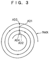
- Step ST2 the disk 101 is set to a reproduced state at the sextuple speed and placed in a held state at a predetermined address position. That is, as shown in Fig. 3, the optical pick-up unit 103 controls the optical pick-up unit 103 so that the optical pick-up unit 103 track-jumps on an address position AD2 of the immediately preceding track each time the optical pick-up unit 103 comes to a position AD1 of a predetermined address of a track on the disk 101.
- the predetermined address position at which the disk 101 is in the held state will be defined as an address position, e.g., 0 minute, 2 seconds and 0 block on the inner periphery side at which the number of revolutions of the disk 101 increases.
- Step ST3 the system controller 115 identifies or determines whether the disk 101 corresponds to the eccentric disk or the mass eccentric disk. When it is determined that the disk 101 does not correspond to the eccentric disk or the mass eccentric disk, the playback speed is set to the sextuple speed and the control operation is completed. On the other hand, when the disk 101 is found to be either the eccentric disk or the mass eccentric disk in Step ST4, the playback speed is set to the quadruple speed and the control operation is completed.
- Step ST3 The determination or identification in Step ST3 as to whether or not the disk 101 is either the eccentric disk or the mass eccentric disk, is performed according to (1) whether or not the level of the tracking error signal ET during a period except for a track-jump period falls within the predetermined range, (2) whether or not the track-jump period is constant, (3) whether or not the address position where the optical pick-up unit 103 is located, is constant after its track jump, and (4) whether or not the level of the control signal DMO of the spindle motor 102 falls within the predetermined range. That is, its identification is performed according to all the method of (1) through (4). When it is determined that the disk 101 is of either the eccentric disk or the mass eccentric disk according to any of (1) through (4), the disk 101 is determined to be either the eccentric disk or the mass eccentric disk.
- tracking error signal ET Even in the case of the use of the tracking error signal ET, there are two cases: where the tracking signal ET is directly used and where the tracking error signal ET subsequent to its filtering process, which has been transmitted through a low-pass filter, is used. An example of the former will first be described in detail.
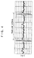
- Fig. 4 shows a tracking error signal ET at the time that the disk 101 is of a normal disk other than the eccentric disk or the mass eccentric disk.
- a level range La of the tracking error signal ET existing during a period other than a track-jump period is narrow.
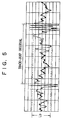
- Fig. 5 shows a tracking error signal ET at the time that the disk 101 is either the eccentric disk or the mass eccentric disk.
- a level range Lb of the tracking error signal ET existing during a period other than a track-jump period becomes broad.
- the disk 101 is of the eccentric disk or the mass eccentric disk, according to whether the level of the tracking error signal ET existing during the period other than the track-jump period falls within the predetermined range. That is, when the level of the tracking error signal ET exceeds the predetermined range, it is identified that the disk 101 is of the mass eccentric disk.
- this identification is performed by the mechanical controller 114 based on the aforementioned compared output of the window comparator 116. Thereafter, information about the identification is supplied to the system controller 115.
- Various noise components are mixed into the tracking error signal ET outputted from the RF signal processing circuit 105 as well as signal components associated with the eccentricity or mass eccentricity of the disk. According to various experiments, it was confirmed that a tracking error signal FMO subjected to a suitable filtering would have an amplitude value corresponding to the amount of eccentricity of the disk or the amount of mass eccentricity of the disk and the correlation between the amount of eccentricity of the disk and the amount of mass eccentricity of the disk appeared well.
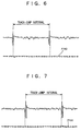
- Fig. 6 is a waveform chart showing the relationship between a track-jump waveform and a tracking error signal FMO at the time that the amount of mass eccentricity of the disk (the value of mass eccentricity thereof) is 0.066gcm. Since the amount of mass eccentricity is extremely small in this case, the correlation between the mass eccentricity and the waveform (variation in the amplitude) is rough or low.
- Fig. 7 is a characteristic diagram similar to that shown in Fig. 6 at the time that the amount of mass eccentricity is 0.2gcm. Since the amount of mass eccentricity is small in this case, the correlation between the mass eccentricity and the waveform is low.
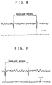
- Fig. 8 is a characteristic diagram at the time that the amount of mass eccentricity is 0.388gcm.
- Fig. 9 is a characteristic diagram at the time that the amount of mass eccentricity is 0.606gcm.
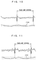
- the amount of mass eccentricity reaches about 0.6gcm, the correlation between the mass eccentricity and the waveform is strongly developed in the waveform of the tracking error signal FMO. Accordingly, the amount of mass eccentricity further increases to reach 0.8gcm as shown in Fig. 10. As the amount of mass eccentricity reaches 1.0gcm, a signal waveform in which the correlation is stronger, is obtained.
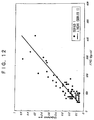
- Fig. 12 shows the relationship between unbalance and a tracking error signal FMO at the time that a large number of disks to be detected are used. It is understood from Fig. 12 that the amplitude of the tracking error signal FMO becomes great in proportion to the amount of unbalance as linearly shown in the drawing.
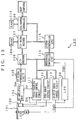
- FIG. 13 shows a first embodiment thereof.
- a tracking error signal ET outputted from a RF signal processing circuit 105 is supplied to a tracking servo control circuit 111 and a low-pass filter 129 where a predetermined frequency or above is cut.
- a cutoff frequency of the low-pas filter 129 slightly varies according to a playback speed defined as the standard for detecting the eccentricity of a disk or unbalance thereof.
- a quadruple speed 2000 rpm
- sextuple speed 3000 rpm
- each of frequencies about twice their rotational frequencies 33Hz and 50Hz
- a cut-off frequency about 100Hz
- a tracking error signal FMO whose high frequency has been cut off, is supplied to a mechanical controller 114 where the eccentricity of the disk or the unbalance thereof is determined.
- the window comparator 116 shown in Fig. 1 can be provided as needed.
- Fig. 14 shows an example using an equalizer output provided within a tracking servo control circuit 111. Only its fragmentary component is partly extracted and shown in the drawing.
- the tracking error signal ET is supplied to a tracking coil TC through a preamplifier 130, a switch 131, an equalizer amplifier 132 and a power amplifier 133. Control on the radial direction of the disk is executed by the tracking coil of control biaxial coils of an objective lens (not shown).
- a switch 131 is turned off when no tracking servo is done.
- the switch 131 is controlled by the mechanical controller 114.
- a tracking error signal TRO corresponding to the output of the equalizer amplifier 132 is supplied to a thread servo control circuit 112.
- the thread servo control circuit 112 is composed of an equalizer amplifier 140 and a power amplifier 141.
- the equalizer amplifier 140 is supplied with a command signal issued from the mechanical controller 114 as well as with the tracking error signal TRO to perform control for shifting the optical pick-up unit 103 in a desired direction.
- a portion of the tracking error signal TRO supplied to the equalizer amplifier 140 is supplied to the low-pass filter 129 where a tracking error signal FMO related to the eccentricity or unbalance of the disk is extracted.
- the tracking error signal FMO subjected to filtering is supplied to the mechanical controller 114.
- FIG. 15 A configuration shown in Fig. 15 is a modification of Fig. 13.
- An output FMO' of an equalizer amplifier 140 provided within the thread servo control circuit 112 is supplied to the mechanical controller 114 through a low-pass filter 129 as a tracking error signal FMO.
- Figs. 16 through 19 are respectively characteristic diagrams of the tracking error signal FMO subjected to the filtering in Fig. 15.
- a cut-off frequency of the low-pass filter 129 slightly varies according to a playback speed to be detected.
- the playback speed to be detected ranges from a quadruple to an octuple speeds
- a range of 100 Hz to 150 Hz is selected as the cut-off frequency of the low-pass filter 129.
- the optical pick-up unit 103 track-jumps in a holding state. Thereafter, the optical pick-up unit 103 is separated from an address position AD2 of the immediately preceding track with respect to an address position AD1 (see Fig. 3) and is placed in an address position of a track on the inner periphery side or an address position of a track on the outer periphery side.
- the disk 101 is of the unbalance disk, a self-induced vibration is produced so that the disk 101 and the optical pick-up unit 103 vibrate. Therefore, the optical pick-up unit 103 is not properly placed in the address position AD2 of the immediately preceding track with respect to the address position AD1 in the same manner as the eccentric disk after the optical pick-up unit 103 has track-jumped in the holding state.
- the disk 101 is of the eccentric disk or the unbalance disk, can be identified according to whether or not the address position where the optical pick-up unit 103 is located after the optical pick-up unit 103 has track-jumped. That is, when the address position of the optical pick-up unit 103 after having track-jumped, is not fixed, it is identified that the disk 101 is either the eccentric disk or the unbalance disk.
- this identification is carried out by the mechanical controller 114 based on a subcode address extracted by the CD decoder 106. Further, information about the identification is supplied to the system controller 115.
- Fig. 16A typically illustrates a tracking error signal ET at the time that the disk 101 is either the eccentric disk or unbalance disk.
- the optical pick-up unit 103 is placed in an address position AD3 (see Fig. 3) on the outer periphery side of an address position AD1 at a time t1, the optical pick-up unit 103 is immediately controlled to jump over the inner periphery side by two tracks at a time t2 so as to be placed in an address position AD2.
- AD3 see Fig. 3
- AD4 see Fig.
- the optical pick-up unit 103 jumps over the track at a time t12 at which the track is reproduced from the address position AD4 to the address position AD2.
- Fig. 16B typically shows a tracking error signal ET at the time that the disk 101 is not the eccentric disk or the unbalance disk. Since, in this case, the optical pick-up unit 103 is always located in an address position AD2 after it has jumped over the track, a track jump interval becomes constant.
- the disk 101 is of either the eccentric disk or the unbalance disk, according to whether the track jump interval is constant. That is, when the track jump interval is unfixed, it is identified that the disk 101 is either the eccentric disk or the unbalance disk.
- this identification is performed by the mechanical controller 114 that controls the track jump. Further, information about the identification is supplied to the system controller 115.
- Fig. 17B shows a control signal DMO of the spindle motor 102 at the time that the disk 101 is a general disk other than the eccentric disk or the unbalance disk. A level range of the control signal DMO is narrow.
- Fig. 17A illustrates a tracking error signal ET in that case.
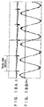
- Fig. 18B shows a control signal DMO of the spindle motor 102 at the time that the disk 101 is an eccentric disk whose eccentricity is 210 ⁇ m. A level range of the control signal DMO becomes broad.
- Fig. 18A shows a tracking error signal ET in that case.
- Fig. 19B illustrates a control signal DMO of the spindle motor 102 at the time that the disk 101 is of the unbalance disk. A level range of the control signal DMO becomes broad in the same manner as the eccentric disk.
- Fig. 19A shows a tracking error signal ET in that case.
- the spindle motor 102 is little accelerated or decelerated when the general disk is at hold and upon release rotation, whereas when the general disk is of either the eccentric disk or the unbalance disk, the spindle motor 102 is not rotated uniformly at the hold and upon the release rotation, so that the spindle motor 102 is frequently accelerated or decelerated.
- the disk 101 is of either the eccentric disk or the unbalance disk, according to whether or not the level of the control signal DMO of the spindle motor 102 falls within a predetermined range. That is, when the level of the control signal DMO exceeds the predetermined range, the disk 101 is identified as either the eccentric disk or the unbalance disk.
- this identification is performed by the mechanical controller 114 based on the compared output of the aforementioned window comparator 117. Information about the identification is supplied to the system controller 115.
- the playback speed is set to the sextuple speed
- the playback speed is set to the quadruple speed other than the sextuple speed. This is because the reduction of the playback speed from the sextuple speed to the quadruple speed can lessen the influence of the external vibration or impact of the predetermined level or more.
- the level of the tracking error signal ET exceeds a predetermined range, the interval of the track jump in the hold state is not fixed and the address position of the optical pick-up unit 103 after its track jump is not fixed, in the same manner as when the disk 101 is of either the eccentric disk or the unbalance disk. Further, the level of the control signal DMO of the spindle motor 102 exceeds the predetermined range.
- the identification as to whether or not the external vibration or impact of the predetermined level or more occurs is performed in accordance with all the methods of (1) to (4) referred to above or by some selected from the methods.
- the identification as to whether or not the external vibration or impact of the predetermined level or more occurs is performed when the CD-ROM drive device is not supplied with the read command from the host computer and is placed in a standby state and when it is supplied with the read command from the host computer and placed in a playback state.
- the identification as to whether or not the external vibration or impact of the predetermined level or more occurs is performed as a sextuple speed playback hold state at intervals of constant times, for example.
- the vibration or impact is not necessarily limited to a continuous one. Therefore, even if it is first identified that the external vibration or impact of the predetermined level or more has occurred, and the playback speed is set to the quadruple speed, when it is identified from its subsequent identification that the external vibration or impact of the predetermined level or more does not occur, the playback speed is set to the sextuple speed again.
- the identification as to whether or not the external vibration or impact of the predetermined level or more is not performed in the playback state.
- the resonance point f0 of the insulator mounted as a damping material between the base unit and the base unit holder is set so as to sufficiently attenuate the resonance point of the vibration characteristic of the base unit, high performance can be maintained against the external vibration or impact.
- the playback speed is set to the quadruple speed other than the sextuple speed.
- the generation of the self-induced vibration is controlled upon reproduction. Even if the resonance point f0 of the insulator does not escape from the number of revolutions to he used, as described above, the self-induced vibration can be prevented from being transmitted to the outside through the insulator. Since the occurrence of the self-induced vibration is controlled even if the disk 101 is of the unbalance disk, the tracking control of the optical pick-up unit 103 becomes easy, so that data can be reproduced from the disk 101 satisfactorily. Since the playback speed is set to the quadruple speed when the disk 101 is of the eccentric disk, the tracking control of the optical pick-up unit 103 becomes easy and the reproduction of data from the disk 101 can be performed satisfactorily.
- the playback speed is set to the sextuple speed, it is determined whether or not the external vibration or impact of the predetermined level or more.
- the playback speed is set to the quadruple speed other than the sextuple speed. Therefore, the influence of the external vibration or impact of the predetermined level on the playback operation can be lessened.
- the present invention can be applied to the CD-ROM drive device 100 capable of reproducing data at the standard, quadruple or sextuple speed.
- the present invention can be further applied even to a CD-ROM drive device capable of reproducing data even at speeds such as octuple, dodecuple, ... speeds.
- the determination as to whether or not the aforementioned disk 101 is of either the eccentric disk or the unbalance disk, and the determination as to whether the external vibration or impact of the predetermined level occurs, are successively performed from the maximum speed and the set values for the playback speed may be set low successively.
- the CD-ROM drive device capable of data at the standard, quadruple, sextuple and octuple speeds, for example, it is first distinguished upon mounting the disk to the CD-ROM drive device whether or not the disk 101 is not either the eccentric disk or the unbalance disk in a state in which the data is being reproduced at the octuple speed. When it is determined that the disk 101 is not either the eccentric disk or the unbalance disk, the playback speed is set to the octuple speed.
- the disk 101 is determined to be either the eccentric disk or the unbalance disk, it is next determined whether or not the disk 101 is either the eccentric disk or the unbalance disk in a state in which the data is being reproduced at the sextuple speed.
- the playback speed is set to the sextuple speed.
- the playback speed is set to the quadruple speed.
- the playback speed may be successively set to a high playback speed as in the case of the quadruple speed, sextuple speed, octuple speed, tenfold speed, ... contrary perfectly to the above description.
- the aforementioned embodiment has described the utilization of the tracking error signal ET. However, even if the focus error signal EF is used, it can be distinguished in the same manner as described above whether or not the disk 101 is of either the eccentric disk or the unbalance disk and whether the external vibration or impact of the predetermined level or more occurs.
- the present invention is applied to the CD-ROM drive device 100. It is however needless to say that the present invention can be applied to an optical disk drive device capable of recording and reproducing data, such as a CD-R drive device, a magneto-optical disk drive device, a digital video disk drive device, and a mini-disk drive device, and even to a magnetic disk drive device such as a hard disk in the same manner as described above.
- an optical disk drive device capable of recording and reproducing data
- a CD-R drive device such as a CD-R drive device, a magneto-optical disk drive device, a digital video disk drive device, and a mini-disk drive device
- a magnetic disk drive device such as a hard disk in the same manner as described above.
- the disk when it is determined that the disk is of either the eccentric disk or the unbalance disk in a state in which a disk-shaped recording medium is being rotated at a predetermined speed, its rotational speed is lowered.
- its rotational speed is increased.
- the resonance point of the damping material mounted between the base unit and the base unit holder can be set so as to sufficiently attenuate the resonance point of the vibration characteristic of the base unit and so as not to escape from the frequency based on the number of revolutions to be used, thus it is possible to maintain high performance against the external vibration or impact.
- the rotational speed of the disk-shaped recording medium is reduced. It is therefore possible to lessen the influence of the external vibration or impact of the predetermined level or higher on the recording and reproducing operations.
Landscapes
- Rotational Drive Of Disk (AREA)
- Optical Recording Or Reproduction (AREA)
Priority Applications (1)
| Application Number | Priority Date | Filing Date | Title |
|---|---|---|---|
| EP01125075A EP1197964B1 (fr) | 1996-07-25 | 1997-07-24 | Dispositif d'entraînement de disque et méthode pour en fixer la vitesse de rotation |
Applications Claiming Priority (3)
| Application Number | Priority Date | Filing Date | Title |
|---|---|---|---|
| JP19668496 | 1996-07-25 | ||
| JP19668496 | 1996-07-25 | ||
| JP196684/96 | 1996-07-25 |
Related Child Applications (1)
| Application Number | Title | Priority Date | Filing Date |
|---|---|---|---|
| EP01125075A Division EP1197964B1 (fr) | 1996-07-25 | 1997-07-24 | Dispositif d'entraînement de disque et méthode pour en fixer la vitesse de rotation |
Publications (3)
| Publication Number | Publication Date |
|---|---|
| EP0821356A2 true EP0821356A2 (fr) | 1998-01-28 |
| EP0821356A3 EP0821356A3 (fr) | 1999-03-17 |
| EP0821356B1 EP0821356B1 (fr) | 2003-05-21 |
Family
ID=16361882
Family Applications (2)
| Application Number | Title | Priority Date | Filing Date |
|---|---|---|---|
| EP01125075A Expired - Lifetime EP1197964B1 (fr) | 1996-07-25 | 1997-07-24 | Dispositif d'entraînement de disque et méthode pour en fixer la vitesse de rotation |
| EP97112759A Expired - Lifetime EP0821356B1 (fr) | 1996-07-25 | 1997-07-24 | Dispositif d'entraínement de disque et méthode pour en fixer la vitesse de rotation |
Family Applications Before (1)
| Application Number | Title | Priority Date | Filing Date |
|---|---|---|---|
| EP01125075A Expired - Lifetime EP1197964B1 (fr) | 1996-07-25 | 1997-07-24 | Dispositif d'entraînement de disque et méthode pour en fixer la vitesse de rotation |
Country Status (6)
| Country | Link |
|---|---|
| US (2) | US6195322B1 (fr) |
| EP (2) | EP1197964B1 (fr) |
| KR (1) | KR100489316B1 (fr) |
| DE (2) | DE69722087T2 (fr) |
| MY (1) | MY124127A (fr) |
| SG (1) | SG50029A1 (fr) |
Cited By (12)
| Publication number | Priority date | Publication date | Assignee | Title |
|---|---|---|---|---|
| WO1998027549A3 (fr) * | 1996-12-19 | 1998-08-06 | Siemens Nixdorf Ag | Lecteur de cd-rom |
| EP0833328A3 (fr) * | 1996-09-03 | 1998-11-11 | Pioneer Electronic Corporation | Système de lecture d'information enregistrée sur un disque |
| EP1006523A1 (fr) * | 1998-12-03 | 2000-06-07 | Deutsche Thomson-Brandt Gmbh | Contrôle et réglage du courant du moteur d'un appareil d'entraínement de disque d'emmagasinage de données pour l'optimalisation de la vitesse de rotation du disque |
| EP1006524A1 (fr) * | 1998-12-03 | 2000-06-07 | Deutsche Thomson-Brandt Gmbh | Contrôle et réglage du courant du moteur d'un appareil d'entrainement de disque d'emmagasinage de données pour l'optimalisation de la vitesse de rotation du disque |
| EP1049086A1 (fr) * | 1999-03-30 | 2000-11-02 | Lg Electronics Inc. | Appareil et méthode de commande de la vitesse de reproduction d'un disque optique |
| EP1056083A1 (fr) * | 1999-05-24 | 2000-11-29 | Mitsumi Electric Co., Ltd. | Tourne-disque optique et méthode de commande de tourne-disque optique |
| EP1067526A1 (fr) * | 1999-07-08 | 2001-01-10 | Samsung Electronics Co., Ltd. | Appareil et méthode pour lire les donnéees d'un disque optique induisant des vibrations |
| WO2001080234A1 (fr) * | 2000-04-14 | 2001-10-25 | Koninklijke Philips Electronics N.V. | Dispositif et procede |
| GB2381118A (en) * | 2001-08-29 | 2003-04-23 | Samsung Electronics Co Ltd | Determining defective disc type. |
| EP1388859A1 (fr) * | 2002-08-02 | 2004-02-11 | Pioneer Corporation | Appareil et méthode de reproduction d'informations et système pour la correction d'erreurs de données |
| EP1168316A3 (fr) * | 2000-05-30 | 2004-03-24 | Ricoh Company, Ltd. | Appareil de stockage d'information |
| WO2007148265A2 (fr) | 2006-06-20 | 2007-12-27 | Koninklijke Philips Electronics N.V. | Dispositifs et procédés de détermination d'une vitesse de rotation critique d'un support de données optique, surveillance de l'état d'un support de données optique et génération d'un signal de référence |
Families Citing this family (38)
| Publication number | Priority date | Publication date | Assignee | Title |
|---|---|---|---|---|
| US6639884B2 (en) * | 1998-05-15 | 2003-10-28 | Lg Electronics, Inc. | Method and apparatus for controlling high-speed rotation of optical disc |
| US6304528B1 (en) * | 1998-07-31 | 2001-10-16 | Matsushita Electric Industrial Co., Ltd. | Optical disk reproducing apparatus |
| KR20000039575A (ko) * | 1998-12-11 | 2000-07-05 | 구자홍 | 광디스크의 상하 편심량을 보상하는 서보제어장치 및 방법 |
| KR20000047312A (ko) * | 1998-12-31 | 2000-07-25 | 구자홍 | 광 디스크의 재생배속 가변 조정장치 및 조정방법 |
| US7268794B2 (en) | 2000-10-30 | 2007-09-11 | Yamaha Corporation | Method of printing label on optical disk, optical disk unit, and optical disk |
| JP3956756B2 (ja) * | 2001-10-31 | 2007-08-08 | ヤマハ株式会社 | 光ディスク記録装置 |
| JP4062976B2 (ja) * | 2002-05-31 | 2008-03-19 | ヤマハ株式会社 | 光ディスクへの画像形成装置および画像形成方法 |
| JP3758614B2 (ja) | 2002-06-28 | 2006-03-22 | ヤマハ株式会社 | 光ディスク記録装置及び光ディスクに対する画像形成方法 |
| US20040141445A1 (en) * | 2003-01-17 | 2004-07-22 | Hanks Darwin Mitchel | Radial position registration for a trackless optical disc surface |
| US7219840B2 (en) * | 2003-01-17 | 2007-05-22 | Hewlett-Packard Development Company, L.P. | Calibrating fine actuator using a reference pattern |
| US7196715B2 (en) * | 2003-01-17 | 2007-03-27 | Hewlett-Packard Development Company, L.P. | Speed control using drive current profile |
| US7671880B2 (en) * | 2003-01-17 | 2010-03-02 | Hewlett-Packard Development Company, L.P. | Optical disk labeling system and method |
| US6862033B2 (en) * | 2003-02-14 | 2005-03-01 | Hewlett-Packard Development Company, L.P. | Disc media marking |
| US6866354B2 (en) | 2003-04-22 | 2005-03-15 | Hewlett-Packard Development Company, L.P. | Disk shape determining and labeling system |
| US7596062B2 (en) * | 2003-09-09 | 2009-09-29 | Lg Electronics Inc. | Method of preventing optical recording media from being fractured and apparatus thereof |
| US20050058031A1 (en) * | 2003-09-12 | 2005-03-17 | Hanks Darwin Mitchel | Optical disk drive focusing apparatus |
| US20050058044A1 (en) * | 2003-09-12 | 2005-03-17 | Koegler John M. | Optical disk modified for speed and orientation tracking |
| US7084894B2 (en) * | 2003-09-12 | 2006-08-01 | Hewlett-Packard Development Company, L.P. | Optical disc drive focusing apparatus |
| US7177246B2 (en) * | 2003-09-12 | 2007-02-13 | Hewlett-Packard Development Company, L.P. | Optical disk drive focusing apparatus using sum signal |
| US20050058043A1 (en) * | 2003-09-12 | 2005-03-17 | Koegler John M. | Optical disk drive modified for speed and orientation tracking |
| TWI244081B (en) * | 2003-09-24 | 2005-11-21 | Mediatek Inc | Error compensation method and apparatus for optical disk drive |
| KR100589518B1 (ko) * | 2003-10-14 | 2006-06-13 | 주식회사 히타치엘지 데이터 스토리지 코리아 | 광디스크 드라이버에서의 데이터 독출 속도 가변 제어방법 |
| TW200514049A (en) * | 2003-10-15 | 2005-04-16 | Ali Corp | Method for detecting an unbalance disc |
| US20050180306A1 (en) * | 2004-01-29 | 2005-08-18 | Valley Jeffrey M. | Disk labeling kit and method |
| TW200531020A (en) * | 2004-03-02 | 2005-09-16 | Lite On It Corp | Revolving-rate control method of disc reading apparatus |
| TWI261227B (en) * | 2004-03-02 | 2006-09-01 | Lite On It Corp | Method for detecting unbalanced disc |
| JP4212504B2 (ja) * | 2004-03-31 | 2009-01-21 | 株式会社東芝 | ピックアップ制御装置および光ディスク装置 |
| TWI306244B (en) * | 2004-07-13 | 2009-02-11 | Lite On It Corp | Detecting method of unbalanced disc |
| US7496026B2 (en) * | 2004-12-11 | 2009-02-24 | Hewlett-Packard Development Company, L.P. | Optical disc and method of printing optical disc |
| US7324419B2 (en) * | 2004-12-11 | 2008-01-29 | Hewlett-Packard Development Company, L.P. | Focus control via AC input signal |
| CN101000785B (zh) * | 2006-01-13 | 2010-05-12 | 鸿富锦精密工业(深圳)有限公司 | 盘片种类识别方法与系统 |
| JP2008135141A (ja) * | 2006-11-29 | 2008-06-12 | Hitachi-Lg Data Storage Inc | 光ディスク装置及びトラッキング制御方法 |
| JP2008140424A (ja) * | 2006-11-30 | 2008-06-19 | Hitachi Ltd | ディスク装置搭載ビデオカメラ及びビデオカメラの制御方法 |
| JP5094204B2 (ja) * | 2007-05-16 | 2012-12-12 | ティアック株式会社 | 光ディスク装置 |
| JP2008287781A (ja) * | 2007-05-16 | 2008-11-27 | Teac Corp | 光ディスク装置 |
| WO2009067122A1 (fr) * | 2007-11-24 | 2009-05-28 | Hewlett-Packard Development Company, L.P. | Signaux de rayons virtuels pour commander un disque optique |
| CN101577136B (zh) * | 2008-05-08 | 2012-11-07 | 建兴电子科技股份有限公司 | 一种光驱装置 |
| CN101783995B (zh) * | 2009-01-15 | 2014-03-05 | 北京富纳特创新科技有限公司 | 热致发声装置 |
Family Cites Families (26)
| Publication number | Priority date | Publication date | Assignee | Title |
|---|---|---|---|---|
| DE3619258A1 (de) * | 1986-06-07 | 1987-12-10 | Blaupunkt Werke Gmbh | Compact disc (cd)-spieler |
| JP2936656B2 (ja) | 1990-06-25 | 1999-08-23 | ソニー株式会社 | 正圧スライダのローディング装置 |
| JPH0724123B2 (ja) | 1990-10-24 | 1995-03-15 | ソニー ミュージック エンターテインメント インコーポレイテッド | 音声信号またはデジタル信号を高速複製する方法と装置 |
| KR100262791B1 (ko) * | 1991-08-21 | 2000-08-01 | 이데이 노부유끼 | 디스크 구동 장치용 디스크 로딩 기구 |
| US6269061B1 (en) * | 1993-10-07 | 2001-07-31 | Sony Corporation | Servo control system for disk player |
| JP3415288B2 (ja) * | 1993-11-09 | 2003-06-09 | 株式会社東芝 | 情報記録再生装置 |
| JP3155663B2 (ja) * | 1994-05-23 | 2001-04-16 | アルプス電気株式会社 | 光ディスク装置 |
| JPH087498A (ja) | 1994-06-17 | 1996-01-12 | Hitachi Ltd | 記録情報再生装置 |
| JPH087456A (ja) * | 1994-06-17 | 1996-01-12 | Aiwa Co Ltd | 信号再生装置 |
| JPH0855449A (ja) | 1994-08-11 | 1996-02-27 | Sony Corp | ディスクドライブ装置 |
| US5774292A (en) * | 1995-04-13 | 1998-06-30 | International Business Machines Corporation | Disk drive power management system and method |
| JPH09198688A (ja) * | 1996-01-19 | 1997-07-31 | Hitachi Ltd | ディスク再生方法及びディスク再生装置 |
| JPH09204741A (ja) * | 1996-01-24 | 1997-08-05 | Sanyo Electric Co Ltd | ディスク駆動速度制御装置 |
| US5740356A (en) * | 1996-02-01 | 1998-04-14 | Delta Electronics, Inc. | Read-error management during retrieving data storage-medium employing a data-retrieving optical beam |
| SG50422A1 (en) * | 1996-02-07 | 1998-07-20 | Creative Tech Ltd | Pre-calibration system and method for cd-rom drive speed optimization |
| KR0176599B1 (ko) * | 1996-05-14 | 1999-04-15 | 김광호 | 씨디-롬 드라이브의 구동방법 |
| US6009053A (en) * | 1996-05-16 | 1999-12-28 | Tottori Sanyo Electric Co., Ltd. | Optical disk vibration sensing and reproducing device |
| JPH1069709A (ja) * | 1996-06-21 | 1998-03-10 | Teac Corp | デ−タ再生方法及び装置 |
| JPH1011882A (ja) * | 1996-06-27 | 1998-01-16 | Toshiba Corp | ディスク再生装置とその制御方法 |
| JP3092657B2 (ja) * | 1996-07-10 | 2000-09-25 | ティアック株式会社 | デ−タ再生方法及び装置 |
| US5963520A (en) * | 1996-07-10 | 1999-10-05 | Teac Corporation | Method and apparatus for high speed data recovery from CD-ROMS or like disks or varying qualities |
| JP3442243B2 (ja) * | 1996-07-12 | 2003-09-02 | ティアック株式会社 | デ−タ再生方法及び装置 |
| JPH1083615A (ja) * | 1996-07-17 | 1998-03-31 | Teac Corp | デ−タ再生方法及び装置 |
| JPH1040640A (ja) * | 1996-07-24 | 1998-02-13 | Hitachi Ltd | ディスク再生方法およびディスク再生装置 |
| ES2150292T3 (es) | 1996-12-19 | 2000-11-16 | Siemens Nixdorf Inf Syst | Unidad de cd-rom. |
| US5893048A (en) * | 1997-01-13 | 1999-04-06 | Dell Usa, L. P. | Method and apparatus for identifying vibration level of previously tested CD ROM discs |
-
1997
- 1997-07-22 US US08/898,064 patent/US6195322B1/en not_active Expired - Lifetime
- 1997-07-24 DE DE69722087T patent/DE69722087T2/de not_active Expired - Lifetime
- 1997-07-24 KR KR1019970034637A patent/KR100489316B1/ko not_active Expired - Fee Related
- 1997-07-24 DE DE69736640T patent/DE69736640T2/de not_active Expired - Lifetime
- 1997-07-24 EP EP01125075A patent/EP1197964B1/fr not_active Expired - Lifetime
- 1997-07-24 EP EP97112759A patent/EP0821356B1/fr not_active Expired - Lifetime
- 1997-07-25 MY MYPI97003395A patent/MY124127A/en unknown
- 1997-07-25 SG SG1997002643A patent/SG50029A1/en unknown
-
2000
- 2000-08-31 US US09/653,426 patent/US6317399B1/en not_active Expired - Lifetime
Cited By (30)
| Publication number | Priority date | Publication date | Assignee | Title |
|---|---|---|---|---|
| EP0833328A3 (fr) * | 1996-09-03 | 1998-11-11 | Pioneer Electronic Corporation | Système de lecture d'information enregistrée sur un disque |
| WO1998027549A3 (fr) * | 1996-12-19 | 1998-08-06 | Siemens Nixdorf Ag | Lecteur de cd-rom |
| US6493300B2 (en) | 1996-12-19 | 2002-12-10 | Fujitsu Siemens Computers Gmbh | CD-ROM drive having adjustable multiple speed ranges |
| EP1006523A1 (fr) * | 1998-12-03 | 2000-06-07 | Deutsche Thomson-Brandt Gmbh | Contrôle et réglage du courant du moteur d'un appareil d'entraínement de disque d'emmagasinage de données pour l'optimalisation de la vitesse de rotation du disque |
| EP1006524A1 (fr) * | 1998-12-03 | 2000-06-07 | Deutsche Thomson-Brandt Gmbh | Contrôle et réglage du courant du moteur d'un appareil d'entrainement de disque d'emmagasinage de données pour l'optimalisation de la vitesse de rotation du disque |
| US6233212B1 (en) | 1998-12-03 | 2001-05-15 | Deutsche Thomson-Brandt Gmbh | Monitoring and adjusting a motor current in a disk data drive to optimize a disk rotation speed |
| EP1647984A1 (fr) * | 1999-03-30 | 2006-04-19 | LG Electronics Inc. | Appareil et méthode de commande de la vitesse de reproduction d'un disque optique |
| EP1049086A1 (fr) * | 1999-03-30 | 2000-11-02 | Lg Electronics Inc. | Appareil et méthode de commande de la vitesse de reproduction d'un disque optique |
| US6826136B1 (en) | 1999-03-30 | 2004-11-30 | Lg Electronics Inc. | Apparatus and method for controlling reproduction speed of an optical disk |
| EP1056083A1 (fr) * | 1999-05-24 | 2000-11-29 | Mitsumi Electric Co., Ltd. | Tourne-disque optique et méthode de commande de tourne-disque optique |
| US6351441B1 (en) | 1999-05-24 | 2002-02-26 | Junichi Andoh | Regulatable optical disc drive and method of controlling a regulatable optical disc drive |
| CN1294586C (zh) * | 1999-07-08 | 2007-01-10 | 三星电子株式会社 | 用于从产生振动的光盘中复制数据的装置和方法 |
| US6958964B1 (en) | 1999-07-08 | 2005-10-25 | Samsung Electronics Co., Ltd. | Apparatus for reproducing data from an optical disc inducing vibration and method thereof |
| EP1067526A1 (fr) * | 1999-07-08 | 2001-01-10 | Samsung Electronics Co., Ltd. | Appareil et méthode pour lire les donnéees d'un disque optique induisant des vibrations |
| CN1310236C (zh) * | 2000-04-14 | 2007-04-11 | 皇家菲利浦电子有限公司 | 记录和/或再现周期性变化的信息的设备和方法 |
| WO2001080234A1 (fr) * | 2000-04-14 | 2001-10-25 | Koninklijke Philips Electronics N.V. | Dispositif et procede |
| US6816445B2 (en) | 2000-04-14 | 2004-11-09 | Koninklijke Philips Electronics N.V. | Device and method |
| EP1168316A3 (fr) * | 2000-05-30 | 2004-03-24 | Ricoh Company, Ltd. | Appareil de stockage d'information |
| US6930964B2 (en) | 2000-05-30 | 2005-08-16 | Ricoh Company, Ltd. | Information storage apparatus |
| US7120103B2 (en) | 2000-05-30 | 2006-10-10 | Ricoh Company, Ltd. | Information storage apparatus |
| US7453783B2 (en) | 2000-05-30 | 2008-11-18 | Ricoh Company, Ltd. | Information storage apparatus |
| GB2381118B (en) * | 2001-08-29 | 2003-12-24 | Samsung Electronics Co Ltd | Apparatus and method for determining disc type |
| GB2381118A (en) * | 2001-08-29 | 2003-04-23 | Samsung Electronics Co Ltd | Determining defective disc type. |
| US7274640B2 (en) | 2001-08-29 | 2007-09-25 | Samsung Electronics Co., Ltd. | Apparatus and method for determining disc type |
| EP1388859A1 (fr) * | 2002-08-02 | 2004-02-11 | Pioneer Corporation | Appareil et méthode de reproduction d'informations et système pour la correction d'erreurs de données |
| US7106679B2 (en) | 2002-08-02 | 2006-09-12 | Pioneer Corporation | Information reproducing apparatus and method, and error correction system |
| WO2007148265A2 (fr) | 2006-06-20 | 2007-12-27 | Koninklijke Philips Electronics N.V. | Dispositifs et procédés de détermination d'une vitesse de rotation critique d'un support de données optique, surveillance de l'état d'un support de données optique et génération d'un signal de référence |
| WO2007148265A3 (fr) * | 2006-06-20 | 2008-03-06 | Koninkl Philips Electronics Nv | Dispositifs et procédés de détermination d'une vitesse de rotation critique d'un support de données optique, surveillance de l'état d'un support de données optique et génération d'un signal de référence |
| CN101473377B (zh) * | 2006-06-20 | 2011-07-27 | 皇家飞利浦电子股份有限公司 | 用于确定光学数据载体的临界旋转速度、监控光学数据载体的状况以及生成参考信号的设备和方法 |
| US8027232B2 (en) | 2006-06-20 | 2011-09-27 | Koninklijke Philips Electronics N.V. | Devices and methods for determining a critical rotation speed of an optical data carrier, monitoring a condition of an optical data carrier, and generating a reference signal |
Also Published As
| Publication number | Publication date |
|---|---|
| MY124127A (en) | 2006-06-30 |
| DE69736640D1 (de) | 2006-10-19 |
| DE69722087D1 (de) | 2003-06-26 |
| KR100489316B1 (ko) | 2005-08-04 |
| EP0821356A3 (fr) | 1999-03-17 |
| EP0821356B1 (fr) | 2003-05-21 |
| SG50029A1 (en) | 1998-06-15 |
| US6195322B1 (en) | 2001-02-27 |
| DE69722087T2 (de) | 2004-03-18 |
| DE69736640T2 (de) | 2007-09-13 |
| EP1197964A1 (fr) | 2002-04-17 |
| EP1197964B1 (fr) | 2006-09-06 |
| KR980011278A (ko) | 1998-04-30 |
| US6317399B1 (en) | 2001-11-13 |
Similar Documents
| Publication | Publication Date | Title |
|---|---|---|
| EP1197964B1 (fr) | Dispositif d'entraînement de disque et méthode pour en fixer la vitesse de rotation | |
| US5161142A (en) | Disk playing apparatus for playing CLV disks | |
| US6351440B1 (en) | Disk reproducing speed control method and a disk reproducing apparatus using this method | |
| US6826136B1 (en) | Apparatus and method for controlling reproduction speed of an optical disk | |
| JP2851597B2 (ja) | 光ディスクシステムにおけるディスク自動判別方法及び装置 | |
| US20020034140A1 (en) | Disk reproducing speed control method and a disk reproducing apparatus using this method | |
| JP3903527B2 (ja) | ディスクドライブ装置およびその回転速度設定方法 | |
| JP3670806B2 (ja) | ディスクプレーヤーの偏重心ディスク検知方法 | |
| JPH10143991A (ja) | 偏重心ディスク検出方法及びディスク再生装置 | |
| KR100219276B1 (ko) | 디스크 배속 재생 제어 방법 및 그 장치 | |
| KR100480624B1 (ko) | 디스크의 편중심 량 측정 방법 및 장치 | |
| JPH1074357A (ja) | ディスクプレーヤーの振動制御装置 | |
| KR20020050691A (ko) | 디스크의 회전에 의해 발생되는 회전진동량 검출방법 | |
| JP2011192336A (ja) | ディスク再生装置およびディスク再生方法 | |
| JP2000011531A (ja) | ディスクプレーヤーの偏重心ディスク検知方法 | |
| KR100195613B1 (ko) | 디스크 재생방법 | |
| JPH08249797A (ja) | 光ディスク再生装置 | |
| KR100746775B1 (ko) | 광디스크 장치에서의 스핀들 모터 제어방법 | |
| KR19990080062A (ko) | 광픽업의 탐색모드에서 목표위치 이동방법 | |
| JPH1055606A (ja) | ディスクプレーヤーの偏重心ディスク検知方法 | |
| JPH1064175A (ja) | ディスクプレーヤーの振動制御装置 | |
| JPH11126417A (ja) | ディスクプレーヤーの偏重心ディスク検知方法 | |
| KR20010027912A (ko) | 광 기록재생기의 트랙킹 제어 방법 및 장치 | |
| JPH07320281A (ja) | 光ディスク装置 | |
| JPH1145502A (ja) | 対物レンズ駆動装置 |
Legal Events
| Date | Code | Title | Description |
|---|---|---|---|
| PUAI | Public reference made under article 153(3) epc to a published international application that has entered the european phase |
Free format text: ORIGINAL CODE: 0009012 |
|
| AK | Designated contracting states |
Kind code of ref document: A2 Designated state(s): DE FR GB NL |
|
| PUAL | Search report despatched |
Free format text: ORIGINAL CODE: 0009013 |
|
| AK | Designated contracting states |
Kind code of ref document: A3 Designated state(s): AT BE CH DE DK ES FI FR GB GR IE IT LI LU MC NL PT SE |
|
| 17P | Request for examination filed |
Effective date: 19990719 |
|
| AKX | Designation fees paid |
Free format text: DE FR GB NL |
|
| 17Q | First examination report despatched |
Effective date: 20010227 |
|
| RAP1 | Party data changed (applicant data changed or rights of an application transferred) |
Owner name: SONY CORPORATION |
|
| GRAH | Despatch of communication of intention to grant a patent |
Free format text: ORIGINAL CODE: EPIDOS IGRA |
|
| GRAH | Despatch of communication of intention to grant a patent |
Free format text: ORIGINAL CODE: EPIDOS IGRA |
|
| GRAA | (expected) grant |
Free format text: ORIGINAL CODE: 0009210 |
|
| AK | Designated contracting states |
Designated state(s): DE FR GB NL |
|
| REG | Reference to a national code |
Ref country code: GB Ref legal event code: FG4D |
|
| REF | Corresponds to: |
Ref document number: 69722087 Country of ref document: DE Date of ref document: 20030626 Kind code of ref document: P |
|
| ET | Fr: translation filed | ||
| PLBE | No opposition filed within time limit |
Free format text: ORIGINAL CODE: 0009261 |
|
| STAA | Information on the status of an ep patent application or granted ep patent |
Free format text: STATUS: NO OPPOSITION FILED WITHIN TIME LIMIT |
|
| 26N | No opposition filed |
Effective date: 20040224 |
|
| REG | Reference to a national code |
Ref country code: GB Ref legal event code: 746 Effective date: 20120703 |
|
| REG | Reference to a national code |
Ref country code: DE Ref legal event code: R084 Ref document number: 69722087 Country of ref document: DE Effective date: 20120614 |
|
| PGFP | Annual fee paid to national office [announced via postgrant information from national office to epo] |
Ref country code: GB Payment date: 20120719 Year of fee payment: 16 |
|
| PGFP | Annual fee paid to national office [announced via postgrant information from national office to epo] |
Ref country code: FR Payment date: 20120806 Year of fee payment: 16 |
|
| PGFP | Annual fee paid to national office [announced via postgrant information from national office to epo] |
Ref country code: NL Payment date: 20120719 Year of fee payment: 16 |
|
| REG | Reference to a national code |
Ref country code: NL Ref legal event code: V1 Effective date: 20140201 |
|
| GBPC | Gb: european patent ceased through non-payment of renewal fee |
Effective date: 20130724 |
|
| REG | Reference to a national code |
Ref country code: FR Ref legal event code: ST Effective date: 20140331 |
|
| PG25 | Lapsed in a contracting state [announced via postgrant information from national office to epo] |
Ref country code: NL Free format text: LAPSE BECAUSE OF NON-PAYMENT OF DUE FEES Effective date: 20140201 Ref country code: GB Free format text: LAPSE BECAUSE OF NON-PAYMENT OF DUE FEES Effective date: 20130724 |
|
| PG25 | Lapsed in a contracting state [announced via postgrant information from national office to epo] |
Ref country code: FR Free format text: LAPSE BECAUSE OF NON-PAYMENT OF DUE FEES Effective date: 20130731 |
|
| PGFP | Annual fee paid to national office [announced via postgrant information from national office to epo] |
Ref country code: DE Payment date: 20140721 Year of fee payment: 18 |
|
| REG | Reference to a national code |
Ref country code: DE Ref legal event code: R119 Ref document number: 69722087 Country of ref document: DE |
|
| PG25 | Lapsed in a contracting state [announced via postgrant information from national office to epo] |
Ref country code: DE Free format text: LAPSE BECAUSE OF NON-PAYMENT OF DUE FEES Effective date: 20160202 |