EP1006524A1 - Contrôle et réglage du courant du moteur d'un appareil d'entrainement de disque d'emmagasinage de données pour l'optimalisation de la vitesse de rotation du disque - Google Patents
Contrôle et réglage du courant du moteur d'un appareil d'entrainement de disque d'emmagasinage de données pour l'optimalisation de la vitesse de rotation du disque Download PDFInfo
- Publication number
- EP1006524A1 EP1006524A1 EP99123075A EP99123075A EP1006524A1 EP 1006524 A1 EP1006524 A1 EP 1006524A1 EP 99123075 A EP99123075 A EP 99123075A EP 99123075 A EP99123075 A EP 99123075A EP 1006524 A1 EP1006524 A1 EP 1006524A1
- Authority
- EP
- European Patent Office
- Prior art keywords
- value
- motor current
- property
- disk
- nominal
- Prior art date
- Legal status (The legal status is an assumption and is not a legal conclusion. Google has not performed a legal analysis and makes no representation as to the accuracy of the status listed.)
- Granted
Links
- 238000012544 monitoring process Methods 0.000 title claims abstract description 10
- 238000000034 method Methods 0.000 claims abstract description 87
- 238000012937 correction Methods 0.000 claims description 5
- 230000003247 decreasing effect Effects 0.000 claims description 4
- 230000006870 function Effects 0.000 description 9
- 230000003287 optical effect Effects 0.000 description 9
- 238000012935 Averaging Methods 0.000 description 7
- 238000005259 measurement Methods 0.000 description 5
- 238000010606 normalization Methods 0.000 description 5
- 230000006399 behavior Effects 0.000 description 3
- 230000035939 shock Effects 0.000 description 3
- 230000032683 aging Effects 0.000 description 2
- 238000010586 diagram Methods 0.000 description 2
- 230000001747 exhibiting effect Effects 0.000 description 2
- GNFTZDOKVXKIBK-UHFFFAOYSA-N 3-(2-methoxyethoxy)benzohydrazide Chemical compound COCCOC1=CC=CC(C(=O)NN)=C1 GNFTZDOKVXKIBK-UHFFFAOYSA-N 0.000 description 1
- 230000001133 acceleration Effects 0.000 description 1
- 230000003679 aging effect Effects 0.000 description 1
- 238000013459 approach Methods 0.000 description 1
- 238000011217 control strategy Methods 0.000 description 1
- 230000007423 decrease Effects 0.000 description 1
- 230000001419 dependent effect Effects 0.000 description 1
- 238000006073 displacement reaction Methods 0.000 description 1
- 230000000694 effects Effects 0.000 description 1
- 238000005265 energy consumption Methods 0.000 description 1
- 238000000605 extraction Methods 0.000 description 1
- 238000003780 insertion Methods 0.000 description 1
- 230000037431 insertion Effects 0.000 description 1
- 238000004519 manufacturing process Methods 0.000 description 1
- 230000010355 oscillation Effects 0.000 description 1
- 230000002035 prolonged effect Effects 0.000 description 1
- 230000001105 regulatory effect Effects 0.000 description 1
- 238000012360 testing method Methods 0.000 description 1
Images





Classifications
-
- G—PHYSICS
- G11—INFORMATION STORAGE
- G11B—INFORMATION STORAGE BASED ON RELATIVE MOVEMENT BETWEEN RECORD CARRIER AND TRANSDUCER
- G11B19/00—Driving, starting, stopping record carriers not specifically of filamentary or web form, or of supports therefor; Control thereof; Control of operating function ; Driving both disc and head
- G11B19/20—Driving; Starting; Stopping; Control thereof
- G11B19/28—Speed controlling, regulating, or indicating
Definitions
- the present invention relates to a disk data drive and more precisely to optimizing a disk rotation speed in such a disk data drive.
- a disk data drive uses a disk shaped data carrier to read and / or write data.
- disk data drives may be optical, opto-magnetic or magnetic data drives.
- disk data drives allow to remove and insert optical (Compact Disks, Digital Versatile Disks), opto-magnetic and/or magnetic disks.
- the inserted disk is rotated inside the drive by means of a motor to which a motor current is fed. Once the disk is rotating data may be read from and / or written to the disk using appropriate reading and / or writing means.
- a rate of data reading and / or writing i.e., a quantity of information per unit of time read from and / or written to the disk is dependent on a disk rotation speed. More precisely the greater the disk rotation speed the greater the achievable rate of data reading and / or writing. Due to imperfections of the disk or of the disk data drive a high disk rotation speed may lead to vibrations or other problems which eventually result in data reading and / or writing errors. Therefore the disk rotation speed needs to be adjusted as high as possible but in a way that a tolerable number of reading and / or writing errors occurs.
- the method for monitoring and adjusting a motor current in a disk data drive such to optimise a rotational speed of a disk actuated by a motor with said motor current comprises the steps of
- a first variant of the invention it is started with a low value of the first property and the first property is kept constant only if the measured value exceeds the nominal value, else the value of the first property is increased.
- the method is started under safe conditions, that means under conditions, which are most likely below the optimum value of the first property.
- the device works without problems, e. g. such caused by eccentricity or bad flatness, under these conditions.
- the value of the first property is increased until the optimum, the maximum acceptable value of the first property is reached.
- the method is started with a maximum value of the first property.
- This has the advantage, that in case of high quality disks, which exhibit only very small eccentricity, the optimum value might be reached much more quickly, because for these disks, the optimum value of the first property most likely does not deviate much from the maximum value. If, in average, more high quality disks are used than low quality disks, this variant of the inventive method most likely leads quickly to the desired result.
- the method is started with a certain medium value of the first property which is afterwards increased or decreased depending on whether it exceeds or falls below a threshold being the nominal value.
- the further steps are similar as described above.
- the medium value with which the method is started may be chosen to be a value which most likely equals the optimum value. This value might be determined by averaging the maximum acceptable values for a big number of different disks. In this case only very few steps will have to be performed to reach the optimum value. This means that the device, in average, will be available for the user very quickly after being turned on or after a new disk has been inserted.
- the first property is the rotational speed of the motor while the second property is the motor current of the motor.
- This has the advantage, that usually the motor of such device is controlled to run at a certain rotational speed. In this case it is sufficient to add the possibility to measure the motor current in order to perform the inventive method. No changes of control devices or control strategy is necessary.
- the first property is the motor current while the second property is the rotational speed of the motor.
- the motor current may not exceed a maximum allowable value because it is regulated according to a predefined strategy. This leads to a limitation of energy consumption as well as to reduced wear of the device and thus to enlarged lifetime. Deviation of actual value and nominal value in this case has the opposite meaning of the one for the first solution.
- the value of the first property is kept constant if the actual value of the first property equals a maximum allowable value of the first property of the device independent of whether the criteria for the optimum value of the first property are already reached or not.
- This also has the advantage not to exceed the maximum allowable or desirable motor current or motor speed or disk speed, respectively.
- the conditions of the method set for determination of optimum speed might not be reached before the maximum speed of the device is reached.
- Measuring the value of the second property advantageously includes measuring several samples of the second property and generating a mean value therefrom.
- Using a mean value has the advantage, that errors caused by erroneously detected extremely high or extremely low values do not have negative influence on the method.
- a further advantage lies in the fact that measurement can be started even before a stable state after switching to a different value of the first property is reached. Otherwise it would be necessary to wait until such stable state is surely reached.
- a further advantage lies in the fact that if the control characteristic is very fast, which includes that deviations around the mean value may exist for a certain prolonged time, even these deviations or oscillations are filtered out by generating the mean value.
- the value of the first property is reduced about a certain amount before being kept constant.
- the steps for changing the value of the first property might be taken relatively large because after having reached the criteria for optimum value the actual value is reduced for example about half the value about which the first property it was changed before.
- the large steps for changing the value of the first property which large steps are possible according this variant of the invention make possible even more quickly reaching the optimum value.
- the inventive method is performed each time a different disk is inserted into the disk data drive.
- This has the advantage, that each disk which might have different eccentricity or flatness than the disk before and each insertion operation which also might cause an eccentric mounting of the disk with regard to the device, that means each situation in which the eccentricity most likely changes, is coped with and the value of the first property is adapted accordingly.
- the device was turned off but the disk was kept, or in case that just a long time passed without access to the disk usually no big changes in the eccentricity of the combination of disk and device take place.
- the number of times the method is performed is such reduced to a reasonable but not too high number.
- the method is also performed again if a certain condition is met.
- condition may be a certain time having elapsed after the last performance of the method.
- This has the advantage that changes which might happen during operation but without having changed the disk are compensated for.
- the device may have been exhibited to mechanical shocks e. g. if it is used at a portable device, for example in a laptop computer or in an automotive system.
- mechanical shocks may lead to a certain displacement of the disc with regard to its mounting which also may cause a changed eccentricity.
- Another condition may advantageously be the turning on of the device independent of whether the disk was changed or the same disk is kept.
- external shocks or other influences might have changed the interconnection and thus the actual eccentricity.
- the nominal value of the second property for a certain speed is the maximum advisable value of said second property corresponding to said value of said speed.
- the nominal value can be taken as threshold value. Comparison is such made easy. Another possibility which is a little bit less easy to implement is that the ideal value for the second property is taken as the nominal value. In this case the comparison would mean, that an actual value lying within a certain range around the ideal value would be taken as correct and only values lying outside this allowable range would be taken as indication of excessive deviation from the optimum value.
- a method for normalizing stored nominal values of motor current for determined rotational speeds of a drive motor in a data drive comprises the steps of g) mounting the device with a defined load, h) adjusting the drive motor to a certain rotational speed, i) measuring the actual value of the motor current, k) comparing said actual value of the motor current to a stored nominal value of motor current for said certain rotational speed and l) correcting said stored nominal value of motor current if the actual value of the motor current deviates from said nominal value.
- the defined load may be a certain disk of defined eccentricity.
- the defined load is defined by the absence of a disk. In this case the motor runs without any load.
- the nominal value differs, usually about a certain factor, from the nominal value of the normalizing method. Normalizing is done in order to adapt the nominal values used for the monitoring and adjusting method to changes of mechanical or electrical properties of the device. For example mechanical resistance of the bearings of the motor i. e. friction or dissipation might change with time and thus make necessary a higher motor current to reach the desired rotational speed compared to a new device. If such external changes would not be taken into account, the monitoring and adjusting method described above would lead to incorrect or less optimum results.
- the normalizing method uses a standard, that means no disk, to compare and if necessary amend stored nominal values. If the characteristic of the device is well known, it might be sufficient just to do one measurement and one correction according to which all other nominal values of motor current corresponding to different rotational speeds can be corrected correctly e. g. by calculation.
- the normalizing method steps are repeated for all nominal values usually used or for a certain number of such values to correct these nominal values.
- the missing ones may be calculated from the measured and corrected ones e. g. by interpolation.
- the nominal values are deemed to be correct and the normalizing process is stopped.
- Advantageously correction of a nominal value comprises the steps of m) calculating an offset value by subtracting the nominal value from the actual value of the motor current, n) adding the offset value to the nominal value in order to obtain a corrected nominal value and o) storing the corrected nominal value.
- a solution to the described problem is according to one aspect of the invention seen in a method for monitoring and adjusting a motor current in a disk data drive such to optimize a rotation speed of a disk actuated by a motor fed with the motor current, comprising
- Still another solution to the described problem is according to another aspect of the invention seen in a method for monitoring and adjusting a motor current in a disk data drive such to optimize a rotation speed of a disk actuated by a motor fed with the motor current, comprising
- a relationship between motor current fed to the motor rotating the disk in the disk data drive, and a disk rotation speed may be expressed as a function which attributes determined values of motor current to determined disk rotation speeds. This function may be given as a curve or a table including the determined values in pairs of motor current and rotation speed values. The values delivered by the function may be called nominal motor current and rotation speed values.
- a motor current limitation it may be possible to use a motor current limitation to find a highest possible disk rotation speed, i.e. an optimized speed at which reading and / or writing errors occur in a tolerable number only.
- the motor current is set at a maximum value and the disk rotation speed is measured. If the disk rotation speed is smaller than an expected nominal disk rotation speed value for the maximum value of current according to the established function or if the expected nominal disk rotation speed value is obtained but may not be held constant then a new lower value of motor current is set and thus the disk rotation speed reduced. This is repeated until the disk rotation speed value becomes and remains substantially equal to the expected nominal disk rotation speed value for the value of the motor current used.
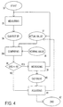
- Fig. 1 a flowchart illustrates a method in which after a start 1 a value of motor current fed to the motor is measured in 2 to obtain a value 3 of motor current for an actual value of the disk rotation speed 4.
- a disk rotation speed and more precisely the actual value of the disk rotation speed 4 may be measured in many different ways, e.g., using data read from the disk or using tachometric information of the disk motor as is well known from a person skilled in the art.
- the value of motor current 3 may typically be obtained using a resistor and appropriate measuring equipment as is well known by a person skilled in the art.
- a comparing 5 compares the value of motor current 3 with a nominal value of motor current 6 which should be flowing at the actual value of the disk rotation speed 4, i.e. with a nominal value of motor current obtained from the above mentioned established function.
- the nominal value of motor current may be obtained for example out of a table (not shown) or a curve (not shown). Other ways of obtaining the nominal value 6 are not excluded.
- a case study 7 checks whether the value of the motor current 3 is substantially equal to the nominal value 6. If the case study 7 returns a positive result (YES) then an increasing 8 increases the disk rotation speed to a new actual value of disk rotation speed and the measuring 2 is initiated again using the new actual value of disk rotation speed in the comparing 5 to find a new nominal value of motor current. Just before increasing the disk rotations speed to the new actual value, the actual value of disk rotation speed is stored as old speed value in 9.
- an adjusting 10 uses the old speed value stored in 9, this value having previously been stored, and adjusts the disk rotation speed to the old speed value. At this point the method comes to an end 11.
- the adjusting 10 in fact results in a reducing of the motor current value which effectively reduces the disk rotation speed to a value at which possible imperfections do not affect the disk data drive anymore.
- the described method allows to have an optimized disk rotation speed for any disk inserted in the disk data drive.
- the measuring 2 may be realized as an average of a plurality of measures.
- a value of motor current 14 is obtained from a current measure 15 and added in 16 to a total measure value 17, the latter having been set equal to 0 by a reset 18 after start 12.
- the established function between nominal values of motor current and disk rotation speeds may be stored in the disk data drive as nominal values.
- a normalization of the established function may be performed regularly. This way aging effects of the bearings may be taken into account.
- the normalization may for example be realized in a test mode during which the motor is rotated at several rotation speeds like 500, 1000, 1500... rpm without a disk in the drive, and the value of motor current is measured at each speed. Offset values between the measured values of motor currents and nominal values stored, obtained by operating a subtraction of the two latter, are used to modify the stored nominal motor current values, e.g. by adding the offset values to the nominal values. Hence an influence from aging components of the disk data drive may be eliminated.
- a start 23 initiates a method for normalizing in a data drive during which no disk is driven by the drive motor.
- a first determined rotation speed of the motor is adjusted in 24 followed by a measurement of the motor current in 25 in order to obtain a first value of the motor current.
- the latter is compared in 26 with a first nominal value of motor current extracted from a table 27 which contains values of nominal motor current associated to values of rotation speeds. If in case study 28 the first value and the first nominal value of motor current appear to be different (YES) then a correcting 29 of the nominal values stored in table 27 is undertaken and a second determined rotation speed is adjusted in 24.
- a case study 30 checks if the adjusted rotation speed is equal to a final rotation speed value and ends the normalizing method if this is the case. This way a series of rotation speed values may be tested until the final rotation speed value has been checked.
- the methods described to this point adjust a rotation speed and measure a motor current which is subsequently compared to a nominal value of motor current.
- Another example of realization of the invention instead comprises adjusting a motor current value and measure a disk rotation speed which is subsequently compared to a nominal value of disk rotation speed.
- a method is started in 33 and a value of disk rotation speed 34 is measured in 35.
- a comparing 355 compares the disk rotation speed 34 with a nominal value of disk rotation speed 36 which one would expect for an actual value of the motor current 37 flowing through the drive motor.
- FIG. 5 shows a diagrammatical view of a device for performing a method according to the invention.
- a disc 50 is shown as data carrier in cross-sectional view. Data is stored on the disk in a data carrying layer 51. Data carrying layer 51 is scanned by a beam of light 52, being produced and received by an optical pick-up 53. Optical pick-up 53 is controlled by and sends electrical signals to a control unit 54. Control unit 54 provides data D to be reproduced. Working of this part of the device is known to those skilled in the art and is thus not described in detail here.
- Disk 50 is mounted to and driven by a disk motor 54.
- Disk motor 54 rotates the disk 50 which is indicated by arrow 56.
- the rotational speed v a which is also named the number of rotations is measured by a rotation sensor 57.
- the actual rotational speed signal v a is fed to a disk speed controller 58 which also receives a desired rotational speed signal v d .
- Disk speed controller 58 provides a control signal to control the disk motor 54 upon which a disk motor driver, not further described here, provides an electric current I to disk motor 54.
- An amperemeter 59 provides for measuring the actual disk motor current I a which signal is fed to a comparison unit 60.
- Comparison unit 60 also receives the actual rotational speed signal v a and compares both values to respective pairs of nominal rotational speed v n and nominal disc motor current I n stored in a memory 61 depending on the result of the comparison according to the inventive method. Comparison unit 60 sets the desired rotational speed v d which is supplied to the disk speed controller 58.
- Figure 6 shows a diagram indicating motor current I over rotational speed v.
- Line 62 shows the relationship of disk motor current I for different rotational speeds v in a standard situation. The curve starts for low rotational speeds approximately linearly and shows a higher increase or non-linear behaviour for larger rotational speeds v. Line 62 indicates the stable condition. In contrast thereto dashed line 63 indicates the starting behaviour for increasing the rotational speed from a low speed to a higher speed v 2 .
- the disk motor current increases sharply short after the desired rotational speed signal v d was increased.
- the disk motor current I also decreases sharply when the motor is already accelerated and approaches v 2 and it most likely falls below line 62, see indication of arrow 64, before the final speed v 2 is reached.
- Dotted line 65 shows, as an example, how the normal characteristic indicated by line 62 might change in case of mechanical resistances e. g. caused by friction or dissipation of or at the disk motor 55 or other mechanically or electrical impacts on the system.
- the adjusting method according to the invention makes it possible to identify such deviation from the standard behaviour.
- the nominal data v n and I n stored in memory 61 which usually complied to line 62 are amended accordingly and corrected nominal values v n and I n are stored to memory 61.
- the more linear shift of line 62 to dotted line 64 it might be possible to just measure one point and to calculate all other points from the measured deviation.
- Dash-dotted line 66 shows the I(v) relation in case that a disk 50 exhibiting eccentricity is used in the device.
- dash-dotted line 66 shows nearly the same characteristic as line 64 but for increasing speeds it deviates therefrom.
- speed v 3 the motor current increases extremely with increasing rotational speed as the high eccentricity causes a high need and thus a high loss of energy.
- dash-dotted line 66 the device would be adapted to the maximum speed v 3 until a different disk is used.
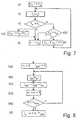
- Figure 7 shows a flowchart illustrating a method for monitoring and adjusting motor current I according to the invention.
- step a) the desired rotational speed v d is set to an initial value v 1 .
- step b) the actual disk motor current I a for the actual rotational speed value v a is measured.
- step c) a comparison of the actual disk motor current I a for the actual rotational speed v a to the nominal disk motor current In corresponding to the same rotational speed v a is done. In case that the measured actual value I a exceeds the nominal value I n the actual rotational speed v a is kept as the disk motor rotational speed v in step d).
- step e) the desired rotational speed v d is increased e.g. by adding a value dv to the actual rotational speed v a . It is then returned to step b).
- step ca) which is to be performed, if desired, after a positive result in step c) is indicated in addition in Fig. 7.
- step ca) the desired rotational speed is set to a lower value than the actual rotational speed v a , for example by reducing the actual rotational speed v a by a difference dv1.
- step cb which is to be performed after a negative result of step c) is also indicated in Fig. 7.
- step d it is checked, whether the actual rotational speed v a equals or exceeds a maximum rotational speed v n for the device. In case of a positive outcome, it is branched to step d). That means that the rotational speed is not increased to higher values than the maximum rotational speed v n set for the device.
- Fig. 8 shows a flowchart illustrating a method for averaging the measured value. These steps would replace step b) of Fig. 7.
- a counting value n and a mean actual value of disk motor current I aM are reset to zero.
- an n-th value of actual motor current I an for the actual rotational speed v a is measured.
- a new value for actual mean current I aM is generated by adding the former actual mean value I aM and the actually measured value I an .
- the counting value n is increased by 1.
- the counting value is compared to a maximum counting value n max . In case the maximum value is not reached it is returned to step bb), else step bf) is performed.
- the actual disk motor current I a is set to be 1/n of the actual mean value of the disk motor current I aM .
- Fig. 9 shows a flowchart illustrating a further example of an inventive method.
- the disk motor current I is set and the actual rotational speed v a is measured and compared to the nominal rotational speed v n corresponding to the actual disk motor current I a .
- the upper left part of Fig. 9 shows a case in which it is started with a low value of the disk motor current I1 in step a1).
- the actual rotational speed v a is measured.
- step c1) the actual rotational speed v a is compared to the nominal rotational speed v n and the motor current I is kept constant in case that v a is smaller than v n .
- step cb1) and e1) being similar to step cb) and e) of Fig. 7, are carried out.
- step cb1) it is indicated the sign "equals 2", however, it is to be understood that also for rotational speeds v a exceeding v n it is branched to step d1).
- Steps b2), c2) and d2) are similar to the respective steps described above, except that in step c2) it is checked whether the actual rotational speed v a exceeds the nominal rotational speed v n .
- step cb2) the actual rotational speed v a is compared to a lowest acceptable rotational speed v l . If v a equals or falls below this minimum rotational speed v l an error message is generated.
- a low rotational speed v l is one which usually does not occur.
- the disk may be mechanically blocked so that the disk motor 55 cannot rotate or can only rotate at an extremely low speed. In this case it is of no use to proceed further.
- Fig. 9 it is shown an example where it is started with a certain medium value of the disk motor current I 3 in step a3).
- the corresponding actual rotational speed v a is measured in step b3) and it is continued with step e2) in case the actual rotational speed v a exceeds the nominal rotational speed v n corresponding to disk motor current I3. If it falls below that value it is continued with step e2).
- the rotational speed v a assumes the nominal rotational speed V n the actual disk motor current I a is kept in step d3).
- Fig. 9 is directed to control the disk motor 55 to assume a certain disk motor current I, it is obvious that a similar method may well be carried out for control regarding rotational speed v.
- Fig. 10 shows a flowchart with regard to a method for normalizing nominal values of motor current In for determined rotational speeds v a .
- the method starts at step g) with mounting a defined load to the device.
- the defined load means that no disk is loaded.
- step h) a desired rotational speed v d is set to an initial value v 1 .
- step i) the actual motor current I a needed to drive a disk motor 55 at rotational speed v a corresponding to v d is measured.
- step k) is this checked whether actual current I a lies within a certain range around the nominal motor current I n for rotational speed v a .
- step m If that is the case, the disk is stopped in step m) and the normalizing procedure is ended. Otherwise the nominal value I n , stored in a memory, is set to assume the value of actual motor current I a .
- step e) the rotational speed is increased and it is returned to step i). This is repeated until the maximum speed is reached. In this case the method ends with step m).
- step n) an offset current I o is determined by subtracting the nominal current I n from the actual current I a .
- steps o) and p) all stored nominal values I n are replaced by the offset value I o added to the old values I n . After all values have been replaced the procedure is stopped with step n).
- optical disk drives in which relatively high rotation speeds of optical disks are desired but may not necessarily be achieved for any optical disk inserted since many optical disk have some kind of manufacturing imperfection.
- optical disk drives include for example DVD-ROM and DVD-RAM drives.
Landscapes
- Control Of Electric Motors In General (AREA)
Priority Applications (1)
| Application Number | Priority Date | Filing Date | Title |
|---|---|---|---|
| EP19990123075 EP1006524B1 (fr) | 1998-12-03 | 1999-11-22 | Contrôle et réglage du courant du moteur d'un appareil d'entrainement de disque d'emmagasinage de données pour l'optimalisation de la vitesse de rotation du disque |
Applications Claiming Priority (3)
| Application Number | Priority Date | Filing Date | Title |
|---|---|---|---|
| EP98403032A EP1006523A1 (fr) | 1998-12-03 | 1998-12-03 | Contrôle et réglage du courant du moteur d'un appareil d'entraínement de disque d'emmagasinage de données pour l'optimalisation de la vitesse de rotation du disque |
| EP98403032 | 1998-12-03 | ||
| EP19990123075 EP1006524B1 (fr) | 1998-12-03 | 1999-11-22 | Contrôle et réglage du courant du moteur d'un appareil d'entrainement de disque d'emmagasinage de données pour l'optimalisation de la vitesse de rotation du disque |
Publications (2)
| Publication Number | Publication Date |
|---|---|
| EP1006524A1 true EP1006524A1 (fr) | 2000-06-07 |
| EP1006524B1 EP1006524B1 (fr) | 2012-02-22 |
Family
ID=26151752
Family Applications (1)
| Application Number | Title | Priority Date | Filing Date |
|---|---|---|---|
| EP19990123075 Expired - Lifetime EP1006524B1 (fr) | 1998-12-03 | 1999-11-22 | Contrôle et réglage du courant du moteur d'un appareil d'entrainement de disque d'emmagasinage de données pour l'optimalisation de la vitesse de rotation du disque |
Country Status (1)
| Country | Link |
|---|---|
| EP (1) | EP1006524B1 (fr) |
Citations (5)
| Publication number | Priority date | Publication date | Assignee | Title |
|---|---|---|---|---|
| US5612933A (en) * | 1994-06-17 | 1997-03-18 | Hitachi, Ltd. | Apparatus for reproducing recorded information with error detection and correction processing |
| EP0821356A2 (fr) * | 1996-07-25 | 1998-01-28 | Sony Corporation | Dispositif d'entraínement de disque et méthode pour en fixer la vitesse de rotation |
| EP0833328A2 (fr) * | 1996-09-03 | 1998-04-01 | Pioneer Electronic Corporation | Système de lecture d'information enregistrée sur un disque |
| WO1998027549A2 (fr) * | 1996-12-19 | 1998-06-25 | Siemens Nixdorf Informationssysteme Ag | Lecteur de cd-rom |
| US5815478A (en) * | 1996-05-14 | 1998-09-29 | Samsung Electronics Co., Ltd. | Method of driving a CD-ROM drive |
-
1999
- 1999-11-22 EP EP19990123075 patent/EP1006524B1/fr not_active Expired - Lifetime
Patent Citations (5)
| Publication number | Priority date | Publication date | Assignee | Title |
|---|---|---|---|---|
| US5612933A (en) * | 1994-06-17 | 1997-03-18 | Hitachi, Ltd. | Apparatus for reproducing recorded information with error detection and correction processing |
| US5815478A (en) * | 1996-05-14 | 1998-09-29 | Samsung Electronics Co., Ltd. | Method of driving a CD-ROM drive |
| EP0821356A2 (fr) * | 1996-07-25 | 1998-01-28 | Sony Corporation | Dispositif d'entraínement de disque et méthode pour en fixer la vitesse de rotation |
| EP0833328A2 (fr) * | 1996-09-03 | 1998-04-01 | Pioneer Electronic Corporation | Système de lecture d'information enregistrée sur un disque |
| WO1998027549A2 (fr) * | 1996-12-19 | 1998-06-25 | Siemens Nixdorf Informationssysteme Ag | Lecteur de cd-rom |
Non-Patent Citations (1)
| Title |
|---|
| STAN S G ET AL: "ADAPTIVE-SPEED ALGORITHMS FOR CD-ROM SYSTEMS", IEEE TRANSACTIONS ON CONSUMER ELECTRONICS, vol. 42, no. 1, 1 February 1996 (1996-02-01), pages 43 - 51, XP000583556 * |
Also Published As
| Publication number | Publication date |
|---|---|
| EP1006524B1 (fr) | 2012-02-22 |
Similar Documents
| Publication | Publication Date | Title |
|---|---|---|
| US6233212B1 (en) | Monitoring and adjusting a motor current in a disk data drive to optimize a disk rotation speed | |
| CN1428769A (zh) | 在变速盘上最佳地记录数据的方法和设备 | |
| EP1006524B1 (fr) | Contrôle et réglage du courant du moteur d'un appareil d'entrainement de disque d'emmagasinage de données pour l'optimalisation de la vitesse de rotation du disque | |
| EP0878795B1 (fr) | Système de commande de moteur de broche pour tourne-disque | |
| CN1578105A (zh) | 电动机及电动机的控制方法 | |
| US6289483B1 (en) | Read retry method in disk drive | |
| US6724695B2 (en) | Method for accessing optical disk by detecting the different between moving command and actually moving | |
| US20030002409A1 (en) | Optical disk recording method and apparatus | |
| JPH11317006A (ja) | アンバランスディスクのリード方法 | |
| US20060279239A1 (en) | Apparatus and method for controlling motor | |
| US7859963B2 (en) | Method and apparatus for adjusting recording power for optical disk device | |
| EP1627384B1 (fr) | Procede de reglage de la vitesse d'un support de donnees dans un appareil du type unite de support de donnees | |
| US20080008063A1 (en) | Optimal Power Control | |
| JP4345167B2 (ja) | 光記録媒体のデータマークの読み/書き装置 | |
| EP1966794B1 (fr) | Procede d'exploitation d'un dispositif d'enregistrement de donnees | |
| US8325574B2 (en) | Optical disc device | |
| CN1215469C (zh) | 动态决定光盘刻录机刻录速度的方法 | |
| US7948837B2 (en) | TE signal polarity determining system and related method thereof | |
| EP1946312B1 (fr) | Procede permettant d'ajuster les parametres d'ecriture, graveur de disque optique et procede permettant d'enregistrer des donnees au moyen de ce dernier | |
| US20060262691A1 (en) | Method for setting data carrier in a data carrier drive apparatus | |
| CN1444218A (zh) | 消除光盘驱动器内部振动的方法和设备 | |
| JP4195426B2 (ja) | データ記録システムにおける系統的エラーの識別 | |
| KR19990004137A (ko) | 디스크의 피트 길이에 따른 rf 레벨 및 에러율을 이용한 등화기 제어 방법 | |
| US20060209650A1 (en) | Method for controlling spindle in optical disc device | |
| EP1629482A2 (fr) | Procede de reglage de la vitesse d'un support de donnees dans un appareil du type unite de support de donnees |
Legal Events
| Date | Code | Title | Description |
|---|---|---|---|
| PUAI | Public reference made under article 153(3) epc to a published international application that has entered the european phase |
Free format text: ORIGINAL CODE: 0009012 |
|
| AK | Designated contracting states |
Kind code of ref document: A1 Designated state(s): DE FR GB IT |
|
| AX | Request for extension of the european patent |
Free format text: AL;LT;LV;MK;RO;SI |
|
| 17P | Request for examination filed |
Effective date: 20001128 |
|
| AKX | Designation fees paid |
Free format text: DE FR GB IT |
|
| 17Q | First examination report despatched |
Effective date: 20080131 |
|
| RAP1 | Party data changed (applicant data changed or rights of an application transferred) |
Owner name: THOMSON |
|
| RAP1 | Party data changed (applicant data changed or rights of an application transferred) |
Owner name: THOMSON LICENSING, S.A. |
|
| RAP1 | Party data changed (applicant data changed or rights of an application transferred) |
Owner name: THOMSON LICENSING |
|
| RAP1 | Party data changed (applicant data changed or rights of an application transferred) |
Owner name: THOMSON LICENSING |
|
| GRAP | Despatch of communication of intention to grant a patent |
Free format text: ORIGINAL CODE: EPIDOSNIGR1 |
|
| GRAS | Grant fee paid |
Free format text: ORIGINAL CODE: EPIDOSNIGR3 |
|
| GRAA | (expected) grant |
Free format text: ORIGINAL CODE: 0009210 |
|
| AK | Designated contracting states |
Kind code of ref document: B1 Designated state(s): DE FR GB IT |
|
| REG | Reference to a national code |
Ref country code: GB Ref legal event code: FG4D |
|
| REG | Reference to a national code |
Ref country code: DE Ref legal event code: R084 Ref document number: 69944045 Country of ref document: DE |
|
| REG | Reference to a national code |
Ref country code: GB Ref legal event code: 746 Effective date: 20120227 |
|
| REG | Reference to a national code |
Ref country code: DE Ref legal event code: R096 Ref document number: 69944045 Country of ref document: DE Effective date: 20120419 |
|
| REG | Reference to a national code |
Ref country code: DE Ref legal event code: R084 Ref document number: 69944045 Country of ref document: DE Effective date: 20120223 |
|
| PG25 | Lapsed in a contracting state [announced via postgrant information from national office to epo] |
Ref country code: IT Free format text: LAPSE BECAUSE OF FAILURE TO SUBMIT A TRANSLATION OF THE DESCRIPTION OR TO PAY THE FEE WITHIN THE PRESCRIBED TIME-LIMIT Effective date: 20120222 |
|
| PLBE | No opposition filed within time limit |
Free format text: ORIGINAL CODE: 0009261 |
|
| STAA | Information on the status of an ep patent application or granted ep patent |
Free format text: STATUS: NO OPPOSITION FILED WITHIN TIME LIMIT |
|
| 26N | No opposition filed |
Effective date: 20121123 |
|
| REG | Reference to a national code |
Ref country code: DE Ref legal event code: R097 Ref document number: 69944045 Country of ref document: DE Effective date: 20121123 |
|
| REG | Reference to a national code |
Ref country code: FR Ref legal event code: PLFP Year of fee payment: 17 |
|
| PGFP | Annual fee paid to national office [announced via postgrant information from national office to epo] |
Ref country code: GB Payment date: 20151130 Year of fee payment: 17 Ref country code: DE Payment date: 20151126 Year of fee payment: 17 |
|
| PGFP | Annual fee paid to national office [announced via postgrant information from national office to epo] |
Ref country code: FR Payment date: 20151120 Year of fee payment: 17 |
|
| REG | Reference to a national code |
Ref country code: DE Ref legal event code: R119 Ref document number: 69944045 Country of ref document: DE |
|
| GBPC | Gb: european patent ceased through non-payment of renewal fee |
Effective date: 20161122 |
|
| REG | Reference to a national code |
Ref country code: FR Ref legal event code: ST Effective date: 20170731 |
|
| PG25 | Lapsed in a contracting state [announced via postgrant information from national office to epo] |
Ref country code: FR Free format text: LAPSE BECAUSE OF NON-PAYMENT OF DUE FEES Effective date: 20161130 |
|
| PG25 | Lapsed in a contracting state [announced via postgrant information from national office to epo] |
Ref country code: GB Free format text: LAPSE BECAUSE OF NON-PAYMENT OF DUE FEES Effective date: 20161122 Ref country code: DE Free format text: LAPSE BECAUSE OF NON-PAYMENT OF DUE FEES Effective date: 20170601 |