EP0821988A1 - Vorrichtung und Verfahren zum Spülen eines simulierten Wanderbettes, das mindestens zwei Leitungen zur Verteilung der Fluide enthält - Google Patents
Vorrichtung und Verfahren zum Spülen eines simulierten Wanderbettes, das mindestens zwei Leitungen zur Verteilung der Fluide enthält Download PDFInfo
- Publication number
- EP0821988A1 EP0821988A1 EP97401813A EP97401813A EP0821988A1 EP 0821988 A1 EP0821988 A1 EP 0821988A1 EP 97401813 A EP97401813 A EP 97401813A EP 97401813 A EP97401813 A EP 97401813A EP 0821988 A1 EP0821988 A1 EP 0821988A1
- Authority
- EP
- European Patent Office
- Prior art keywords
- fluid
- line
- desorbent
- lines
- rinsing
- Prior art date
- Legal status (The legal status is an assumption and is not a legal conclusion. Google has not performed a legal analysis and makes no representation as to the accuracy of the status listed.)
- Granted
Links
- 239000012530 fluid Substances 0.000 title claims abstract description 121
- 238000000034 method Methods 0.000 title claims abstract description 24
- 238000000926 separation method Methods 0.000 claims abstract description 12
- 239000000203 mixture Substances 0.000 claims description 29
- 230000001105 regulatory effect Effects 0.000 claims description 22
- 238000011010 flushing procedure Methods 0.000 claims description 17
- 238000011144 upstream manufacturing Methods 0.000 claims description 6
- 238000000605 extraction Methods 0.000 claims description 5
- 239000000945 filler Substances 0.000 claims description 3
- 238000003795 desorption Methods 0.000 claims description 2
- XLYOFNOQVPJJNP-UHFFFAOYSA-N water Substances O XLYOFNOQVPJJNP-UHFFFAOYSA-N 0.000 claims 1
- 239000002904 solvent Substances 0.000 abstract description 3
- 238000002347 injection Methods 0.000 description 23
- 239000007924 injection Substances 0.000 description 23
- URLKBWYHVLBVBO-UHFFFAOYSA-N Para-Xylene Chemical group CC1=CC=C(C)C=C1 URLKBWYHVLBVBO-UHFFFAOYSA-N 0.000 description 18
- 238000004064 recycling Methods 0.000 description 16
- YXFVVABEGXRONW-UHFFFAOYSA-N Toluene Chemical compound CC1=CC=CC=C1 YXFVVABEGXRONW-UHFFFAOYSA-N 0.000 description 15
- YNQLUTRBYVCPMQ-UHFFFAOYSA-N Ethylbenzene Chemical compound CCC1=CC=CC=C1 YNQLUTRBYVCPMQ-UHFFFAOYSA-N 0.000 description 14
- CTQNGGLPUBDAKN-UHFFFAOYSA-N O-Xylene Chemical group CC1=CC=CC=C1C CTQNGGLPUBDAKN-UHFFFAOYSA-N 0.000 description 14
- IVSZLXZYQVIEFR-UHFFFAOYSA-N m-xylene Chemical group CC1=CC=CC(C)=C1 IVSZLXZYQVIEFR-UHFFFAOYSA-N 0.000 description 14
- 238000004821 distillation Methods 0.000 description 13
- DSNHSQKRULAAEI-UHFFFAOYSA-N 1,4-Diethylbenzene Chemical compound CCC1=CC=C(CC)C=C1 DSNHSQKRULAAEI-UHFFFAOYSA-N 0.000 description 12
- 125000003118 aryl group Chemical group 0.000 description 10
- 238000004891 communication Methods 0.000 description 7
- AFZZYIJIWUTJFO-UHFFFAOYSA-N 1,3-diethylbenzene Chemical compound CCC1=CC=CC(CC)=C1 AFZZYIJIWUTJFO-UHFFFAOYSA-N 0.000 description 6
- 229910052799 carbon Inorganic materials 0.000 description 6
- 239000000470 constituent Substances 0.000 description 5
- 238000003780 insertion Methods 0.000 description 4
- 230000037431 insertion Effects 0.000 description 4
- 239000003463 adsorbent Substances 0.000 description 3
- 150000001768 cations Chemical class 0.000 description 3
- 238000009792 diffusion process Methods 0.000 description 3
- 238000001179 sorption measurement Methods 0.000 description 3
- 229910021536 Zeolite Inorganic materials 0.000 description 2
- 125000004432 carbon atom Chemical group C* 0.000 description 2
- HNPSIPDUKPIQMN-UHFFFAOYSA-N dioxosilane;oxo(oxoalumanyloxy)alumane Chemical group O=[Si]=O.O=[Al]O[Al]=O HNPSIPDUKPIQMN-UHFFFAOYSA-N 0.000 description 2
- 230000000694 effects Effects 0.000 description 2
- 239000012535 impurity Substances 0.000 description 2
- 239000010457 zeolite Substances 0.000 description 2
- 229910052788 barium Inorganic materials 0.000 description 1
- DSAJWYNOEDNPEQ-UHFFFAOYSA-N barium atom Chemical compound [Ba] DSAJWYNOEDNPEQ-UHFFFAOYSA-N 0.000 description 1
- 230000000052 comparative effect Effects 0.000 description 1
- 238000011109 contamination Methods 0.000 description 1
- 230000008878 coupling Effects 0.000 description 1
- 238000010168 coupling process Methods 0.000 description 1
- 238000005859 coupling reaction Methods 0.000 description 1
- 230000003247 decreasing effect Effects 0.000 description 1
- 239000000463 material Substances 0.000 description 1
- 238000005259 measurement Methods 0.000 description 1
- 238000005070 sampling Methods 0.000 description 1
Images

Classifications
-
- B—PERFORMING OPERATIONS; TRANSPORTING
- B01—PHYSICAL OR CHEMICAL PROCESSES OR APPARATUS IN GENERAL
- B01D—SEPARATION
- B01D15/00—Separating processes involving the treatment of liquids with solid sorbents; Apparatus therefor
- B01D15/08—Selective adsorption, e.g. chromatography
- B01D15/10—Selective adsorption, e.g. chromatography characterised by constructional or operational features
- B01D15/18—Selective adsorption, e.g. chromatography characterised by constructional or operational features relating to flow patterns
- B01D15/1814—Recycling of the fraction to be distributed
- B01D15/1821—Simulated moving beds
- B01D15/1828—Simulated moving beds characterised by process features
-
- B—PERFORMING OPERATIONS; TRANSPORTING
- B01—PHYSICAL OR CHEMICAL PROCESSES OR APPARATUS IN GENERAL
- B01D—SEPARATION
- B01D15/00—Separating processes involving the treatment of liquids with solid sorbents; Apparatus therefor
- B01D15/08—Selective adsorption, e.g. chromatography
- B01D15/10—Selective adsorption, e.g. chromatography characterised by constructional or operational features
- B01D15/18—Selective adsorption, e.g. chromatography characterised by constructional or operational features relating to flow patterns
- B01D15/1814—Recycling of the fraction to be distributed
- B01D15/1821—Simulated moving beds
- B01D15/1828—Simulated moving beds characterised by process features
- B01D15/1835—Flushing
-
- B—PERFORMING OPERATIONS; TRANSPORTING
- B01—PHYSICAL OR CHEMICAL PROCESSES OR APPARATUS IN GENERAL
- B01D—SEPARATION
- B01D15/00—Separating processes involving the treatment of liquids with solid sorbents; Apparatus therefor
- B01D15/08—Selective adsorption, e.g. chromatography
- B01D15/10—Selective adsorption, e.g. chromatography characterised by constructional or operational features
- B01D15/18—Selective adsorption, e.g. chromatography characterised by constructional or operational features relating to flow patterns
- B01D15/1814—Recycling of the fraction to be distributed
- B01D15/1821—Simulated moving beds
- B01D15/1842—Simulated moving beds characterised by apparatus features
Definitions
- the invention relates to a device and a method for rinsing in a separation in simulated moving bed comprising at least two circulation lines connecting the distribution plates to the external fluids.
- this flow control system on the incoming rinse loop, outgoing rinse is ill-suited to a programmable flow rate varying, for example, from zero during a certain part of the period at a certain setpoint during another part of the period, thus allowing efficient scanning with a minimum of displaced volume.
- An alternative technique implemented for example in the Eluxyl process consists in connecting each distributor tray located between two consecutive beds to outside by at least two separate circulation or distribution lines.
- the object of the invention is therefore to remedy this drawback while carrying out rinses with volumes or flow rates as low as possible and in all cases lower than those of the processes related to the use of the rotary valve and a single line common to the four main flows per bed.
- a second object of the invention is to minimize the rinsing volumes by increasing their efficiency, by carrying out very high flow rinses during a part of the period only.
- a mobile bed separation device simulated against the current or co-current with which a rinsing device is combined lines conveying various fluids.
- a simulated moving bed separation device comprising a plurality of columns chromatographic or interconnected column sections (2, 4, 6), a distribution (3) of fluids between each column section, at least two (10, 30) and at most four separate lines (10, 20, 30, 40) of circulation connected to the platform distribution (3), each circulation line being connected to a different line among the two supply lines (100, 300) through which the load and the desorbent and among the two withdrawal lines (200, 400) through which a fluid with the desired product and a fluid with the non-desired product (s); or a first circulation line (10) being connected to two lines (100, 200) in which the desorbent and the fluid circulate respectively with the sought product, a second circulation line (30) being connected to a load feed line (300) and a third circulation line being connected to a line for withdrawing the fluid with the non-desi
- the device is characterized in that the circulation line (10) of fluid containing the desired product comprises a rinsing line (250) of a incoming secondary fluid (desorbent, fluid with the desired product or fluid with the desired product depleted by desorbent) or an outgoing fluid (250) (mixture desorbent and fluid with the desired product).
- a rinsing line (250) of a incoming secondary fluid desorbent, fluid with the desired product or fluid with the desired product depleted by desorbent
- an outgoing fluid 250
- the device may contain at least one other circulation lines (30) which encloses a rinse line (350) of a fluid entering (desorbent) in the distributor plate or a fluid leaving (350) the distributor plate (charge, fluid containing the product or products not sought).
- the line for rinsing the incoming fluid can include at least one pressurized enclosure or a feed pump (101 or 253) in said fluid connected respectively to a flow control member (351, 352 or 256, 257 fig. 1).
- the rinsing line (350 or 250) of the outgoing fluid can include a flow regulator (352, 351 or 256, 257).
- the invention also relates to a method using the device. So more detailed, a simulated moving bed separation process is described in a separation zone or adsorber comprising a plurality of columns or sections interconnected columns, a fluid distribution tray between each column section, at least two (10, 30) and at most four rows (10, 20, 30, 40) separate circulation connected to the distribution plate, each line being connected to a different line among the four lines containing the four flows main (fluid comprising the product sought, fluid comprising the product not sought, charge, desorbent) or a first circulation line (10) being connected to two lines (100, 200) in which the desorbent and the fluid with the desired product, a second circulation line (30) being connected to a load supply line (300) and a third circulation line being connected to a fluid withdrawal line with the unwanted product (400); or else a first line of circulation being connected to two lines (300 and 400) in which the charge and the fluid with the non-sought product (s), a second line of circulation being connected to a desorbent supply line (100
- the process is characterized in that performs at least one rinsing of the line (10) containing the fluid comprising the product sought by a secondary fluid entering each tray distribution or by a fluid leaving each of said plates for at least part of a period of time between two successive permutations of lines main flow supply and main flow withdrawal lines, or during all of said periods, the secondary fluid being chosen from the group formed by the desorbent, the fluid comprising the desired product and the fluid comprising the desired product rid of at least part of the desorbent.
- the rinsing of said line can be carried out sequentially with the fluid secondary, downstream of the extract racking and upstream of the feed feed if the desired product is in the extract and downstream of the raffinate and upstream of the desorbent if the product sought is in the raffinate.
- the rinsing of said line can be carried out continuously by the secondary fluid on all platens at once during all periods of the cycle.
- the distribution plate when the distribution plate includes three or four circulation lines, you can also rinse of the line carrying the desorbent (100) by desorbent (line 150).
- the rinsing of the line containing the fluid comprising the desired product can be performed with a ratio of flushing fluid flow, compared to the flow of load between 0.005 and 0.4 advantageously between 0.02 and 0.15 and preferably between 0.04 and 0.08.
- This same ratio can be used for rinsing the line containing the fluid including the product not sought.
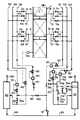
- a separation unit in simulated moving bed consisting of at least one column 1 separated into several beds or sections 2, 4, 6, ... the number of beds being between 4 and 24.
- Each bed is filled with an adsorbent, for example an X or Y zeolite exchanged by a cation from group lla and a cation from group la, when it is a question of separating the paraxylene from the aromatic C 8 cut.
- each bed is separated from the immediately lower bed by a distributor 3, 5 ...
- This distributor is connected to the outside of the column either by 2 lines (10 and 30) of circulation by reference to figure 1 either by 3 lines, or by 4 lines (10, 20, 30, 40) by reference to figure 2.
- a line of desorbent 100 serves each of the beds by valves 21a, 61a.
- the desorbent is sent successively to each bed by line 100 by means of a pump 101 and its flow is precisely regulated through a flow meter 102 and a control valve 103.
- a line of extract 200 serves each of the beds by valves 22a, 62a.
- the extract is withdrawn, at controlled rate, successively from each bed by line 200 by means of the flow meter 201 and valve 202 then is directed to a distillation column 203 where for example paraxylene is withdrawn at the head by line 206 while the desorbent consisting essentially of paradiethylbenzene is drawn off by the line 205 before being returned to the pump 101.
- This column also includes a racking tray 204 making it possible to take depleted extract by desorbing.
- a load line 300 serves each of the beds by the valves 41a, 81a. Load is sent successively in each bed by line 300 by means of a pump 301 and its flow is precisely regulated by a flow meter 302 and a control valve 303.
- the raffinate is withdrawn under pressure control successively of each bed by line 400 by means of the control valve 401 and the pressure sensor 402 located on the column. It is directed to a distillation column 403 where, for example, a mixture of paraffins and naphthenes, ethylbenzene, metaxylene and orthoxylene is drawn off at the head by line 405 while the desorbent consisting essentially of paradiethylbenzene is withdrawn by line 404 to pump 101.
- Lines 30, 70 lead to lines 41, 42, 43 and lines 81, respectively, 82, 83. These lines are used to convey dirty fluids, for example the raffinate and the load if the desired product is in the extract.
- These lines 30, 70 can be rinsed either continuously or sequentially using lines 43, 83 and valves 43a, 83a. When you want a continuous rinse, you will use valves able to regulate a constant and equal flow whatever the position of introduction. On the contrary, if we want a sequential rinsing, we will use all or nothing valves.
- the valves 43a, 83a allow the communication of each of the distributors 3, 5 with a line 350 allowing either to withdraw or inject a flushing fluid into lines 30, 70.
- valve 352 and the flow meter 351 allow regulating the injection rate.
- Lines 20, 60 are used exclusively to transport desorbent from line 100 or desorbent intended rinsing from line 150 through valves 24a, 64a. They can be rinsed either continuously or sequentially using on lines 24, 64.
- valves 24a, 64a When you want a continuous rinsing, you will use valves able to regulate a constant and substantially equal flow regardless of the position of introduction. On the contrary when we want a sequential rinsing, we will use all or nothing valves.
- valves 24a, 64a allow the communication of each of the distributors 3, 5 with a line 150 allowing either to withdraw or to introduce a flushing fluid in lines 20, 60.
- valve 151a It can be injected using line 150 of the desorbent.
- valve 151a we open the valve 151a and the flow is regulated by the flow meter 152 and the control valve 153 (the valve 154a is closed).
- valve 154a is opened (valve 151a is closed) and regulates the flow through the flow meter 152 and the control valve 153.
- Lines 10, 50 Connected to lines 10, 50 are lines 23, 63.
- Lines 10, 50 are used exclusively to convey extract via valves 22a, 62a (to line 200) and a rinsing current from or to the line 250 via the valves 23a, 63a.
- valves suitable for regulating a constant and substantially equal flow regardless of the insertion position At otherwise when you want a sequential rinse, you will use valves all or nothing.
- Lines 40, 80 are used exclusively to transport load from line 300 via valves 41a, 81a or desorbent intended for rinsing the line from line 450 by through valves 44a, 84a.
- valves suitable for regulating a constant and substantially equal flow regardless of the insertion position. At otherwise when you want a sequential rinse, you will use valves all or nothing.
- Lines 30, 70 Connected to lines 30, 70 are lines 43, 83. Lines 30, 70 are used exclusively to convey the raffinate via valves 42a, 82a to line 400 and a rinsing current to line 350 via valves 43a, 83a.
- valves suitable for regulating a constant and substantially equal flow regardless of the insertion position At otherwise when you want a sequential rinse, you will use valves all or nothing.
- a simulated moving bed separation unit consists of 24 adsorbent beds arranged in two columns of twelve beds each.
- the inside diameter of each bed is 915 mm.
- the heights of beds 1 to 11 and 13 to 23 are all substantially equal while the heights of beds 12 and 24 have been reduced: in accordance with French patent 2,721,529, the beds located near the recycling pumps are shorter in order to compensate for the effects induced by the dead volume of each recycling loop.
- each bed On average, the volume of each bed is 0.686 m 3 to which are added on average 0.031 m 3 per bed representing all the dead volumes (recycling loops and internal volumes of the distributors).
- a distributor Between each two beds is a distributor separating these beds and connected to the outside by two separate lines. The first of these two lines leads to a charge valve, a raffinate valve and a flush valve for the "dirty" service line. Each on-off flush valve is followed by a manual valve to adjust the flow rates. The second of these two lines leads to a desorbent valve, an extract valve and a "clean" service line rinse valve.
- the charge circulation line is equipped with a pump, a flow control valve and a flow meter, it is connected to each of the 24 “dirty” service lines on each of the floors.
- the raffinate circulation line is equipped with a pressure control valve and a flow meter, and is connected to each of the 24 “dirty” service lines on each of the floors.
- the “dirty” rinse circulation line is equipped with a flow meter. It can be connected either to the delivery of the desorbent pump or to the supply of the raffinate distillation column. It therefore allows either incoming rinses or outgoing rinses.
- the desorbent circulation line is equipped with a pump, a flow control valve and a flow meter, it is connected to each of the 24 "clean" service lines on each of the floors.
- the extract circulation line is equipped with a flow control valve and a flow meter, it is connected to each of the 24 "clean" service lines on each of the floors.
- the “clean” flushing circulation line is equipped with a pump, a flow control valve and a flow meter. It can be connected either to the suction of the desorbent pump or just downstream from the extract control valve, or finally to the 25th tray of the extract distillation column (the first forty are in the rectification zone, the last twenty are in the exhaustion zone).
- This clean rinse distribution line therefore makes it possible to carry out incoming rinses either of desorbent or of extract, or of extract depleted in desorbent.
- the adsorbent is an X zeolite whose main compensation cation is barium.
- the desorbent consists of 97.9% by paradiethylbenzene, 1.6% by metadiethylbenzene and 0.5% by about ten different aromatic constituents with 10 carbon atoms.
- the charge to be separated consists of 3.1% paraffins and naphthenes, 1.2% toluene, 11.6% ethylbenzene, 21.9% paraxylene, 39.1% metaxylene, 21.9% orthoxylene and 0.2% various aromatic constituents with 9 carbon atoms.
- the unit is operated isothermally at 165 ° C.
- the suction pressure of two recycling pumps is regulated at 9 bar.
- the flow compositions are obtained by the average of the analyzes of five series of samples (desorbent, extract, charge, raffinate) taken every six hours. The debits correspond to an average measurement over 24 hours. Purity is calculated on the composition of the extract, the yield on the compositions and flow rates of extract and raffinate.
- the material balance shows a difference of at most 0.3% for the majority constituents (aromatic C 8 and paradiethylbenzene) and at most 2.6% for the minority constituents (paraffins and naphthenes, toluene, aromatic C 9 , metadietylbenzene , other C 10 aromatics).
- composition of the extract is: paraffins and naphthenes 0.009%, toluene 1.121%, ethylbenzene 0.055%, paraxylene 35.324%, metaxylene 0.095%, orthoxylene 0.048%, C 9 aromatic 0.017%, metadiethylbenzene 1.021%, paradiethylbenzene 62.012%, C 10 aromatic 0.298%.
- Purity is calculated on paraffins and naphthenes, ethylbenzene, metaxylene, orthoxylene and aromatic C8s. Toluene is not counted since it is removed in another distillation column. The purity is 99.37%.
- the composition of the raffinate is: paraffins and naphthenes 1.58%, toluene 0.271%, ethylbenzene 5.887%, paraxylene 0.555%, metaxylene 19.903%, orthoxylene 11.65%, C 9 aromatic 0.097%, metadiethylbenzene 0.952%, paradiethylbenzene 58.82 %, C 10 aromatic 0.30%. The yield is therefore 95%.
- Example 1 is repeated, further connecting the "clean" rinsing circuit to the delivery of the desorbent pump.
- the flushing desorbent flow rate is 0.96 m 3 / h.
- Example 1 The temperature and the pressure are kept identical to Example 1. As previously there are 5 beds in zone 1, 7 beds in zone 3 and 3 beds in zone 4. In however, between the extract sample and the rinse injection (zone 5) is 1 bed and between the rinse injection and the charge injection (zone 2) there are 8 beds.
- the desorbent, charge and raffinate flow rates are kept strictly identical to those of Example 1.
- the flows in zone 1, in zone 2, in zone 3 and in zone 4 are kept strictly identical to those of Example 1.
- the extract flow rate is now 7.91 m 3 / h and the flow rate in the bed located between the extract sample and the rinsing injection (zone 5) has decreased by 0.96 m 3 / h compared to the previous case; as a result, the average recycling rate is now 56.06 m 3 / h.
- the paraxylene content in the extract is no more than 31.072%.
- the impurity contents are: paraffins and naphthenes 0.002%, ethylbenzene 0.044%, metaxylene 0.051%, orthoxylene 0.026%, C 9 aromatics 0.008%.
- the purity is therefore 99.58%, the yield remains almost unchanged: 95.02%.
- Example 2 The conditions of Example 2 are repeated, except that the flow rate of rinsing desorbent is reduced from 0.96 m 3 / h to 0.48 m 3 / h.
- the extract flow is then 7.43 m 3 / h, the average recycling flow is 56.08 m 3 / h.
- composition of the extract is: paraffins and naphthenes 0.002%, ethylbenzene 0.045%, paraxylene 33.044%, metaxylene 0.0052%, orthoxylene 0.026%, C 9 aromatics 0.008%.
- the purity is therefore 99.60%, the yield remains 95%.
- example 2 The conditions of example 2 are repeated, except that the flow rate of the rinsing desorbent is reduced to 0.24 m 3 / h.
- the extract flow is then 7.19 m 3 / h, the average recycling flow is 56.09 m 3 / h.
- the purity is 99.59%, the yield is 94.99%.
- Example 3 is repeated, changing only the distribution of the beds between zones 5 and 2. There are 2 beds between the extract sample and the rinsing injection. There are 7 beds between the rinse injection and the charge injection. The average recycling rate changes since there is one more bed in zone 5 and one less in zone 2: instead of 56.08 m 3 / h (example 3) it drops to 56.06 m 3 / h. The purity is 99.65%, the yield is 94.99%.
- the clean rinsing circuit is connected downstream of the extract control valve.
- the rinse extract flow rate is 0.48 m 3 / h.
- the "clean" rinsing circuit is connected to the column's withdrawal plate extract (25th tray located in the rectification zone).
- the distillation column is set so that the paraxylene concentration on this pan is about 65%. This figure corresponds to the maximum concentration of paraxylene in the adsorber. This maximum is located in zone 2.
- the clean rinsing circuit is connected downstream of the extract control valve.
- the rinse extract flow rate is 0.48 m 3 / h.
- valves connected to the clean rinsing circuit are actuated twice at during the 56 second period.
- Zones 2 and 5 during the entire period, have only 2 beds each and their flow rates are maintained identical to those of Examples 6 to 8. 5 beds are alternately in zone 5 during the first part of the period then in zone 2 during the second part of the period.
- the recycling flow rate setpoint is the arithmetic mean of the flows in zone 5 and in zone 2 (table III). It therefore appears a 6th zone, exactly as if we injected two clean rinsing currents, permanently, in two different places of the adsorber.
- the clean rinsing circuit is connected to the column withdrawal plate extract.
- Example 14 to be compared with Example 13
- the temperature is brought to 175 ° C. and other conditions are adopted: the flow rates mass are kept compared to Example 13, the volume flow rates all increase by 0.9% (due inversely proportional to the masses load volumes at 165 ° C and 175 ° C).
- the permutation period is reduced from 56 seconds to 55.6 seconds.
- the first and second parts of the period are 27.8 s each.
- the purity is 99.86%, the yield 94.76%.
- Example 15 (sequential rinsing of the clean line and continuous outgoing rinsing of the dirty line)
- Example No. 13 the desorbent flow rate is increased by 0.24 m 3 / h (therefore from 18.3 m 3 / h to 18.54 m 3 / h).
- the dirty rinse line is connected to the supply of the raffinate distillation column. All the dirty rinse all-or-nothing valves are open and the flow rates on each of the stages are adjusted so that a continuous flow rate of 0.01 m 3 / h is taken from each of the distributors. All the dirty rinses leaving the unit represent a total of 0.24 m 3 / h. This stream is sent to the feed to the raffinate distillation column.
- Example 13 is repeated with, in addition, the two flushing valves which are operated sequentially. There is one bed of difference between the desorbent injection and the dirty rinse sample, four beds between the dirty rinse sample and the extract sample.
- the desorbent flow rate is 18.54 m 3 / h and the dirty rinse flow rate is 0.24 m 3 / h.
- the purity is 99.84% and the yield 94.65%.
- Example 10 The conditions of Example 10 are repeated, in addition the dirty rinse line is connected to the delivery of the desorbent pump. All-or-nothing flush valves dirty are operated sequentially. Dirty rinse is injected in the same place clean rinsing: four beds after extracting the extract.
- the flow in zone 5 drops by 0.24 m 3 / h
- the extract flow increases by 0.24 m 3 / h (from 7.43 m 3 / h to 7.67 m 3 / h).
- the average recycling rate drops from 56.02 m 3 / h to 55.98 m 3 / h.
- the purity is 99.68% and the yield 95.49%.
- Example 18 (rinsing in two different positions of the clean line and rinsing incoming sequential from dirty line)
- Example 12 and 17 The conditions of Examples 12 and 17 are repeated.
- the dirty rinse is injected 7 beds after the extracting of the extract and two beds before the charge injection.
- a flow rate of 0.24 m 3 / h of desorbent is used for this purpose.
- the average recycling rate is 55.95 m 3 / h.
- the purity is 99.78%, the yield 95.34%.
- Example 19 (rinsing in two different positions of the "clean” line with the extract depleted in desorbent and sequential rinsing leaving the line " clean ")
- Example 14 The conditions of Example 14 are repeated, adding to it the outgoing sequential rinsing described in Example 16. The purity is 99.89% and the yield 94.67%.
- the descriptive part which follows is common to Examples 20 to 24.
- the distributors separating the beds have been replaced by distributors connected to the outside by four separate lines. The first of these lines leads to a charge valve and a flushing valve. The second of these lines leads to a raffinate valve and a flushing valve. The third line leads to a desorbent valve and a rinse valve. The fourth line leads to an extract valve and a rinse valve.
- composition of the filler and the desorbent as well as the nature of the sieve molecular are identical to those of Examples 1 to 19.
- Example 22 (sequential rinsing in two different positions of the line extract and sequential rinsing entering the desorbent line)
- Example 23 (sequential rinsing in two different positions of the extract line, sequential rinsing entering the desorbent line, sequential rinsing leaving the charge line)
- example 22 The conditions of example 22 are repeated, in addition the desorbent flow rate is increased by 0.24 m 3 / h and a current of 0.24 m 3 is withdrawn by the rinsing valve connected to the charge line. / h a bed downstream of the desorbent injection.
- Example 24 (sequential rinsing in two different positions of the extract line, sequential rinsing entering the desorbent line, sequential rinsing leaving the charge line, sequential rinsing leaving the raffinate line)
- example 23 The conditions of example 23 are repeated, in addition the desorbent flow rate is increased by 0.24 m 3 / h and a current of 0.24 m 3 is withdrawn by the rinsing valve connected to the raffinate line. / h a bed downstream of the desorbent injection. The outgoing rinse stream is returned to the raffinate distillation. The purity obtained is 99.91%, the yield 94.62%.
- Examples 2 to 19 and 21 to 24 show that it is essential to rinse the line (s) clean, to achieve significant gains in purity and to separate the line from raffinate and that of charge to obtain a significant gain in yield.
- the rinsing of dirty lines brings only small purity gains at the cost of one sharp drop in yield.
Landscapes
- Chemical & Material Sciences (AREA)
- Life Sciences & Earth Sciences (AREA)
- Sustainable Development (AREA)
- Analytical Chemistry (AREA)
- Chemical Kinetics & Catalysis (AREA)
- Treatment Of Liquids With Adsorbents In General (AREA)
- Extraction Or Liquid Replacement (AREA)
- Organic Low-Molecular-Weight Compounds And Preparation Thereof (AREA)
- Cleaning In General (AREA)
- Physical Or Chemical Processes And Apparatus (AREA)
Applications Claiming Priority (2)
| Application Number | Priority Date | Filing Date | Title |
|---|---|---|---|
| FR9609773A FR2751888B1 (fr) | 1996-07-31 | 1996-07-31 | Dispositif et procede de rincage en lit mobile simule comportant au moins deux lignes de distribution de fluides |
| FR9609773 | 1996-07-31 |
Publications (2)
| Publication Number | Publication Date |
|---|---|
| EP0821988A1 true EP0821988A1 (de) | 1998-02-04 |
| EP0821988B1 EP0821988B1 (de) | 2003-10-22 |
Family
ID=9494767
Family Applications (1)
| Application Number | Title | Priority Date | Filing Date |
|---|---|---|---|
| EP97401813A Expired - Lifetime EP0821988B1 (de) | 1996-07-31 | 1997-07-28 | Vorrichtung und Verfahren zum Spülen eines simulierten Wanderbettes, das mindestens zwei Leitungen zur Verteilung der Fluide enthält |
Country Status (10)
| Country | Link |
|---|---|
| US (2) | US5882523A (de) |
| EP (1) | EP0821988B1 (de) |
| KR (1) | KR100478770B1 (de) |
| CN (1) | CN1091624C (de) |
| AR (1) | AR008091A1 (de) |
| BR (1) | BR9704141A (de) |
| DE (1) | DE69725662T2 (de) |
| FR (1) | FR2751888B1 (de) |
| ID (1) | ID17971A (de) |
| TW (1) | TW350780B (de) |
Cited By (6)
| Publication number | Priority date | Publication date | Assignee | Title |
|---|---|---|---|---|
| WO2007144476A1 (fr) * | 2006-06-16 | 2007-12-21 | Groupe Novasep | Procede de separation sequence multicolonnes |
| FR2935101A1 (fr) * | 2008-08-19 | 2010-02-26 | Inst Francais Du Petrole | Procede et dispostif de separation en lit mobile simule a debit de fluide de derivation non regule automatiquement |
| FR2956037A1 (fr) * | 2010-02-11 | 2011-08-12 | Inst Francais Du Petrole | Procede et dispositif de separation en lit mobile simule comportant des lignes de derivation d'un lit sur deux avec debits de balayage controles lors des injections et des soutirages |
| WO2012172190A1 (fr) * | 2011-06-16 | 2012-12-20 | IFP Energies Nouvelles | Procédé et dispositif de séparation chromatographique a contre-courant simulé a faible perte de charge et nombre de zones élevé |
| CN105521622A (zh) * | 2014-09-30 | 2016-04-27 | 中国石油化工股份有限公司 | 模拟移动床吸附塔外管路淋洗设备及其在吸附分离中的应用 |
| WO2020216685A1 (fr) * | 2019-04-25 | 2020-10-29 | IFP Energies Nouvelles | Dispositif de distribution par panneaux méridiens avec séparation des réseaux de collecte |
Families Citing this family (22)
| Publication number | Priority date | Publication date | Assignee | Title |
|---|---|---|---|---|
| FR2772634B1 (fr) * | 1997-12-22 | 2000-02-18 | Inst Francais Du Petrole | Procede et dispositif d'amelioration de la purete d'un produit en lit mobile simule |
| FR2777798B1 (fr) * | 1998-04-27 | 2000-06-02 | Inst Francais Du Petrole | Procede et dispositif d'amelioration de la purete d'un produit en lit mobile simule comprenant une recirculation forcee de fluide |
| US6149352A (en) | 1999-02-11 | 2000-11-21 | Keystone Retaining Wall Systems, Inc. | Retaining wall block system |
| AU2002220007A1 (en) | 2000-11-15 | 2002-05-27 | Purdue Research Foundation | Systems and processes for performing separations using a simulated moving bed apparatus |
| ES2396679T3 (es) * | 2003-02-25 | 2013-02-25 | Dupont Nutrition Biosciences Aps | Un sistema de lecho móvil simulado |
| US7544293B2 (en) | 2005-09-26 | 2009-06-09 | Semba Inc. | Valve and process for interrupted continuous flow chromatography |
| EP1775001A1 (de) | 2005-10-13 | 2007-04-18 | Xendo Holding B.V. | Vorrichtung für chromatographische Trennungen |
| KR100741752B1 (ko) | 2005-12-26 | 2007-07-23 | 삼성토탈 주식회사 | 단일 흡착 챔버를 사용하여 공급물을 전처리하는 유사 이동층 흡착 분리 방법 및 그에 사용되는 장치 |
| KR100741749B1 (ko) | 2005-12-26 | 2007-07-23 | 삼성토탈 주식회사 | 최종 제품을 2차 세척 액체로 사용하는 유사 이동층 흡착 분리 방법 |
| FR2904776B1 (fr) * | 2006-08-08 | 2009-01-23 | Inst Francais Du Petrole | Procede et dispositif de separation en lit mobile simule a nombre de vannes reduit |
| FR2907021B1 (fr) * | 2006-10-16 | 2009-02-06 | Inst Francais Du Petrole | Procede et dispositif de separation en lit mobile simule a nombre de vannes de grand diametre reduit |
| FR2913345B1 (fr) * | 2007-03-09 | 2010-06-11 | Inst Francais Du Petrole | Procede et dispositif de separation en lit mobile simule a nombre de vannes et volume de lignes reduits |
| FR2913346B1 (fr) * | 2007-03-09 | 2009-04-24 | Inst Francais Du Petrole | Procede et dispositif de separation en lit mobile simule a nombre de vannes de grand diametre et volume de lignes reduits |
| KR100929115B1 (ko) | 2008-01-17 | 2009-11-30 | 삼성토탈 주식회사 | 추출액을 2차 세척용 액체로 사용하는 유사 이동층 흡착분리 방법 |
| JP5602224B2 (ja) * | 2009-05-29 | 2014-10-08 | エクソンモービル・ケミカル・パテンツ・インク | Parexユニット供給 |
| JP5709974B2 (ja) | 2010-03-30 | 2015-04-30 | エクソンモービル・ケミカル・パテンツ・インク | 分離システム |
| CN102895799B (zh) * | 2011-07-28 | 2015-09-23 | 中国石油化工股份有限公司 | 控制阀数量减少的模拟移动床吸附分离方法和设备 |
| CN102895800B (zh) | 2011-07-28 | 2016-05-25 | 中国石油化工股份有限公司 | 模拟移动床吸附分离方法和设备 |
| US20130153501A1 (en) * | 2011-12-15 | 2013-06-20 | Uop Llc | System and process for recovering products using simulated-moving-bed adsorption |
| US9522863B2 (en) | 2014-02-28 | 2016-12-20 | Exxonmobil Chemical Patents Inc. | Xylene separation process |
| WO2016081113A1 (en) | 2014-11-20 | 2016-05-26 | Exxonmobil Chemical Patents Inc. | Xylene separation process and apparatus |
| FR3072885B1 (fr) | 2017-10-27 | 2019-11-15 | IFP Energies Nouvelles | Nouveau systeme de distribution par panneaux meridiens pour un procede de separation en lit mobile simule utilisant n-colonnes en serie |
Citations (4)
| Publication number | Priority date | Publication date | Assignee | Title |
|---|---|---|---|---|
| EP0075611A1 (de) * | 1981-09-29 | 1983-04-06 | Uop Inc. | Simuliertes Gegenstrom-Sorptions-Verfahren mit Rückfluss, das Ionenaustauscherharze verwendet |
| EP0415822A1 (de) * | 1989-08-28 | 1991-03-06 | Institut Français du Pétrole | Kontinuierliches Verfahren und Vorrichtung für eine chromatographische Trennung einer Mischung von mindestens drei Bestandteilen in drei gereinigte Ausflüsse mittels eines Lösungsmittels bei zwei verschiedenen Temperaturen und/oder Drucken |
| US5156736A (en) * | 1991-05-07 | 1992-10-20 | Schoenrock Karlheinz W R | Simulated moving bed apparatus using a single sorbent bed for separating components from a fluid stream |
| EP0688590A1 (de) * | 1994-06-22 | 1995-12-27 | Institut Francais Du Petrole | Trennungsprozess mittels simulierter Wanderbettchromatographie mit Korrektion für das Totvolumen durch Längenabnahme |
Family Cites Families (14)
| Publication number | Priority date | Publication date | Assignee | Title |
|---|---|---|---|---|
| US515736A (en) * | 1894-03-06 | Food compound | ||
| US547046A (en) * | 1895-10-01 | Binder for sewing-machines | ||
| US4402832A (en) * | 1982-08-12 | 1983-09-06 | Uop Inc. | High efficiency continuous separation process |
| US4498991A (en) * | 1984-06-18 | 1985-02-12 | Uop Inc. | Serial flow continuous separation process |
| US4724081A (en) * | 1986-04-28 | 1988-02-09 | Soken Kagaku Kabushiki Kaisha | Process and apparatus for separation by liquid chromatography |
| JPH0669521B2 (ja) * | 1986-12-23 | 1994-09-07 | 三菱化成エンジニアリング株式会社 | クロマト分離法 |
| JPH0746097B2 (ja) * | 1988-05-17 | 1995-05-17 | 三菱化成エンジニアリング株式会社 | クロマト分離法 |
| US4990259A (en) * | 1988-12-16 | 1991-02-05 | The Amalgamated Sugar Company | Chromatographic separator sorbent bed preparation |
| FR2651148B1 (fr) * | 1989-08-28 | 1992-05-07 | Inst Francais Du Petrole | Procede continu et dispositif de separation chromatographique d'un melange d'au moins trois constituants en trois effluents purifies au moyen de deux solvants. |
| ES2130262T3 (es) * | 1992-04-29 | 1999-07-01 | Inst Francais Du Petrole | Procedimiento y dispositivo de fraccionamiento de una mezcla en lecho movil simulado en presencia de un gas comprimido, de un fluido supercritico o de un liquido subcritico. |
| US5470464A (en) * | 1994-04-06 | 1995-11-28 | Uop | Small scale simulated moving bed separation apparatus and process |
| FR2721528B1 (fr) * | 1994-06-22 | 1996-09-06 | Inst Francais Du Petrole | Procédé de séparation par chromatographie en lit mobile simulé avec correction de volume mort par desynchronisation des périodes. |
| DE4421934A1 (de) * | 1994-06-23 | 1996-01-04 | Ford Werke Ag | Metallisches Profil als Verstärkung einer Kraftfahrzeugtür |
| FR2743002B1 (fr) * | 1995-12-27 | 1998-01-30 | Inst Francais Du Petrole | Procede de regulation d'au moins un debit de fluide circulant dans une boucle de separation chromatographique en lit mobile simule |
-
1996
- 1996-07-31 FR FR9609773A patent/FR2751888B1/fr not_active Expired - Fee Related
-
1997
- 1997-07-25 TW TW086110618A patent/TW350780B/zh not_active IP Right Cessation
- 1997-07-28 EP EP97401813A patent/EP0821988B1/de not_active Expired - Lifetime
- 1997-07-28 AR ARP970103406A patent/AR008091A1/es active IP Right Grant
- 1997-07-28 DE DE69725662T patent/DE69725662T2/de not_active Expired - Lifetime
- 1997-07-30 US US08/903,510 patent/US5882523A/en not_active Expired - Lifetime
- 1997-07-30 BR BR9704141A patent/BR9704141A/pt not_active Application Discontinuation
- 1997-07-30 KR KR1019970035992A patent/KR100478770B1/ko not_active Expired - Lifetime
- 1997-07-31 ID IDP972669A patent/ID17971A/id unknown
- 1997-07-31 CN CN97117422A patent/CN1091624C/zh not_active Expired - Lifetime
-
1998
- 1998-07-20 US US09/119,020 patent/US6017448A/en not_active Expired - Lifetime
Patent Citations (4)
| Publication number | Priority date | Publication date | Assignee | Title |
|---|---|---|---|---|
| EP0075611A1 (de) * | 1981-09-29 | 1983-04-06 | Uop Inc. | Simuliertes Gegenstrom-Sorptions-Verfahren mit Rückfluss, das Ionenaustauscherharze verwendet |
| EP0415822A1 (de) * | 1989-08-28 | 1991-03-06 | Institut Français du Pétrole | Kontinuierliches Verfahren und Vorrichtung für eine chromatographische Trennung einer Mischung von mindestens drei Bestandteilen in drei gereinigte Ausflüsse mittels eines Lösungsmittels bei zwei verschiedenen Temperaturen und/oder Drucken |
| US5156736A (en) * | 1991-05-07 | 1992-10-20 | Schoenrock Karlheinz W R | Simulated moving bed apparatus using a single sorbent bed for separating components from a fluid stream |
| EP0688590A1 (de) * | 1994-06-22 | 1995-12-27 | Institut Francais Du Petrole | Trennungsprozess mittels simulierter Wanderbettchromatographie mit Korrektion für das Totvolumen durch Längenabnahme |
Cited By (18)
| Publication number | Priority date | Publication date | Assignee | Title |
|---|---|---|---|---|
| WO2007144476A1 (fr) * | 2006-06-16 | 2007-12-21 | Groupe Novasep | Procede de separation sequence multicolonnes |
| WO2007144522A3 (fr) * | 2006-06-16 | 2008-02-07 | Groupe Novasep | Procede de separation sequence multicolonnes |
| US8182696B2 (en) | 2006-06-16 | 2012-05-22 | Groupe Novasep | Multicolumn sequential separation process |
| US8465649B2 (en) | 2006-06-16 | 2013-06-18 | Groupe Novasep | Multicolumn sequential separation process |
| FR2935101A1 (fr) * | 2008-08-19 | 2010-02-26 | Inst Francais Du Petrole | Procede et dispostif de separation en lit mobile simule a debit de fluide de derivation non regule automatiquement |
| US8049055B2 (en) | 2008-08-19 | 2011-11-01 | IFP Energies Nouvelles | Process and device for separation in a simulated moving bed with a bypass fluid flow rate that is not regulated automatically |
| FR2956037A1 (fr) * | 2010-02-11 | 2011-08-12 | Inst Francais Du Petrole | Procede et dispositif de separation en lit mobile simule comportant des lignes de derivation d'un lit sur deux avec debits de balayage controles lors des injections et des soutirages |
| US8123951B2 (en) | 2010-02-11 | 2012-02-28 | IFP Energies Nouvelles | Process and apparatus for simulated moving bed separation comprising bypass lines in every other bed and with controlled flushing flow rates during injections and withdrawals |
| FR2976500A1 (fr) * | 2011-06-16 | 2012-12-21 | IFP Energies Nouvelles | Procede et dispositif de sepation chromatographique a contre-courant simule a faible perte de charge et nombre de zones eleve. |
| WO2012172190A1 (fr) * | 2011-06-16 | 2012-12-20 | IFP Energies Nouvelles | Procédé et dispositif de séparation chromatographique a contre-courant simulé a faible perte de charge et nombre de zones élevé |
| CN103596654A (zh) * | 2011-06-16 | 2014-02-19 | Ifp新能源公司 | 具有低压力降和高区数的模拟逆流色谱分离方法和装置 |
| CN103596654B (zh) * | 2011-06-16 | 2015-06-17 | Ifp新能源公司 | 具有低压力降和高区数的模拟逆流色谱分离方法 |
| US9365470B2 (en) | 2011-06-16 | 2016-06-14 | IFP Energies Nouvelles | Simulated countercurrent chromatographic separation process and device with low pressure drop and high number of zones |
| CN105521622A (zh) * | 2014-09-30 | 2016-04-27 | 中国石油化工股份有限公司 | 模拟移动床吸附塔外管路淋洗设备及其在吸附分离中的应用 |
| WO2020216685A1 (fr) * | 2019-04-25 | 2020-10-29 | IFP Energies Nouvelles | Dispositif de distribution par panneaux méridiens avec séparation des réseaux de collecte |
| FR3095351A1 (fr) * | 2019-04-25 | 2020-10-30 | IFP Energies Nouvelles | Dispositif de distribution par panneaux méridiens avec séparation des réseaux de collecte |
| CN113747959A (zh) * | 2019-04-25 | 2021-12-03 | Ifp 新能源公司 | 具有收集网络的分隔的使用子午线嵌板的分布装置 |
| CN113747959B (zh) * | 2019-04-25 | 2023-04-18 | Ifp 新能源公司 | 具有收集网络的分隔的使用子午线嵌板的分布装置 |
Also Published As
| Publication number | Publication date |
|---|---|
| EP0821988B1 (de) | 2003-10-22 |
| FR2751888A1 (fr) | 1998-02-06 |
| BR9704141A (pt) | 1999-08-10 |
| ID17971A (id) | 1998-02-12 |
| CN1176838A (zh) | 1998-03-25 |
| MX9705691A (es) | 1998-06-30 |
| US5882523A (en) | 1999-03-16 |
| KR100478770B1 (ko) | 2005-07-18 |
| CN1091624C (zh) | 2002-10-02 |
| DE69725662D1 (de) | 2003-11-27 |
| KR980008291A (ko) | 1998-04-30 |
| FR2751888B1 (fr) | 1998-09-11 |
| US6017448A (en) | 2000-01-25 |
| AR008091A1 (es) | 1999-12-09 |
| TW350780B (en) | 1999-01-21 |
| DE69725662T2 (de) | 2004-04-29 |
Similar Documents
| Publication | Publication Date | Title |
|---|---|---|
| EP0821988B1 (de) | Vorrichtung und Verfahren zum Spülen eines simulierten Wanderbettes, das mindestens zwei Leitungen zur Verteilung der Fluide enthält | |
| EP0818226B1 (de) | Spülvorrichtung in einer Adsorptionseinheit mit simuliertem Wanderbett und deren Verwendung | |
| EP0923970B1 (de) | Verfahren und Vorrichtung zur Verbesserung der Reinheit eines Produktes durch ein simuliertes Wanderbett | |
| EP2276548B1 (de) | Gradientenelutionsmehrsäulentrennverfahren | |
| EP1325772B1 (de) | Bypassflüssigkeitsinjektionssystem in einem simulierten Wanderbett-Trennungsverfahren | |
| EP1913988B1 (de) | Verfahren und Vorrichtung zur Abscheidung in einem simulierten Fließbett mit einer reduzierten Anzahl von Schiebern großen Durchmessers | |
| EP1600675B1 (de) | Verbessertes Trennungsverfahren und Vorrichtung in einem simulierten Wanderbettsystem | |
| FR2656231A1 (fr) | Procede et equipement pour la separation fractionnaire chromatographique d'un fluide. | |
| EP0415821A1 (de) | Kontinuierliches Verfahren und Vorrichtung für eine chromatographische Trennung einer Mischung von mindestens drei Bestandteilen in drei gereinigte Ausflüsse mittels zwei Lösungsmitteln | |
| FR2677555A1 (fr) | Procede pour la separation fractionnee d'une multitude de constituants de leur melange. | |
| EP0797472B1 (de) | Verfahren zur trennung von schweren und leichten verbindungen durch extraktion mit einem überkritischen fluid und durch nanofiltration | |
| FR2913345A1 (fr) | Procede et dispositif de separation en lit mobile simule a nombre de vannes et volume de lignes reduits | |
| FR2904776A1 (fr) | Procede et dispositif de separation en lit mobile simule a nombre de vannes reduit | |
| FR2956037A1 (fr) | Procede et dispositif de separation en lit mobile simule comportant des lignes de derivation d'un lit sur deux avec debits de balayage controles lors des injections et des soutirages | |
| EP1646437B1 (de) | Verfahren und vorrichtung zur trennung von bestandteilen einer flüssigen beschickung mittels flüssigkeit-flüssigkeit-zentrifugenchromatographie | |
| EP0846483B1 (de) | Spülungsvorrichtung in einer Adsorbtionseinheit eines simulierten Wanderbettes, die zwei Leitungen zur Verteilung der Fluiden enthält und ihre Anwendung | |
| FR2935101A1 (fr) | Procede et dispostif de separation en lit mobile simule a debit de fluide de derivation non regule automatiquement | |
| WO2010020715A1 (fr) | Procédé et dispositif de séparation en lit mobile simulé à débit de fluide de dérivation modulé | |
| CA2272638C (fr) | Dispositif de regulation de debit d'au moins un fluide d'unites de separation par lit mobile simule | |
| FR2721529A1 (fr) | Procédé de séparation par chromatographie en lit mobile simulé avec correction de volume mort par diminution de longueur. | |
| EP0688589A1 (de) | Trennverfahren mittels simulierter Wanderbettchromatographie mit Korrektur des Totvolumens durch Desynchronisation der Perioden | |
| FR2913346A1 (fr) | Procede et dispositif de separation en lit mobile simule a nombre de vannes de grand diametre et volume de lignes reduits | |
| FR2777798A1 (fr) | Procede et dispositif d'amelioration de la purete d'un produit en lit mobile simule comprenant une recirculation forcee de fluide | |
| FR2856313A1 (fr) | Methode de gestion des vannes d'un systeme de separation a lit mobile simule | |
| FR2704158A1 (fr) | Procédé et dispositif de fractionnement d'un mélange en lit mobile simulé en présence d'un gaz comprimé. |
Legal Events
| Date | Code | Title | Description |
|---|---|---|---|
| PUAI | Public reference made under article 153(3) epc to a published international application that has entered the european phase |
Free format text: ORIGINAL CODE: 0009012 |
|
| AK | Designated contracting states |
Kind code of ref document: A1 Designated state(s): DE GB IT NL |
|
| 17P | Request for examination filed |
Effective date: 19980804 |
|
| AKX | Designation fees paid |
Free format text: DE GB IT NL |
|
| RBV | Designated contracting states (corrected) |
Designated state(s): DE GB IT NL |
|
| 17Q | First examination report despatched |
Effective date: 20020816 |
|
| GRAH | Despatch of communication of intention to grant a patent |
Free format text: ORIGINAL CODE: EPIDOS IGRA |
|
| GRAS | Grant fee paid |
Free format text: ORIGINAL CODE: EPIDOSNIGR3 |
|
| GRAA | (expected) grant |
Free format text: ORIGINAL CODE: 0009210 |
|
| AK | Designated contracting states |
Kind code of ref document: B1 Designated state(s): DE GB IT NL |
|
| REG | Reference to a national code |
Ref country code: GB Ref legal event code: FG4D Free format text: NOT ENGLISH |
|
| REF | Corresponds to: |
Ref document number: 69725662 Country of ref document: DE Date of ref document: 20031127 Kind code of ref document: P |
|
| GBT | Gb: translation of ep patent filed (gb section 77(6)(a)/1977) |
Effective date: 20040204 |
|
| PLBE | No opposition filed within time limit |
Free format text: ORIGINAL CODE: 0009261 |
|
| STAA | Information on the status of an ep patent application or granted ep patent |
Free format text: STATUS: NO OPPOSITION FILED WITHIN TIME LIMIT |
|
| 26N | No opposition filed |
Effective date: 20040723 |
|
| REG | Reference to a national code |
Ref country code: DE Ref legal event code: R081 Ref document number: 69725662 Country of ref document: DE Owner name: IFP ENERGIES NOUVELLES, FR Free format text: FORMER OWNER: INSTITUT FRANCAIS DU PETROLE, RUEIL-MALMAISON, HAUTS-DE-SEINE, FR Effective date: 20110331 |
|
| PGFP | Annual fee paid to national office [announced via postgrant information from national office to epo] |
Ref country code: NL Payment date: 20140714 Year of fee payment: 18 Ref country code: DE Payment date: 20140805 Year of fee payment: 18 |
|
| PGFP | Annual fee paid to national office [announced via postgrant information from national office to epo] |
Ref country code: GB Payment date: 20140717 Year of fee payment: 18 |
|
| PGFP | Annual fee paid to national office [announced via postgrant information from national office to epo] |
Ref country code: IT Payment date: 20140717 Year of fee payment: 18 |
|
| REG | Reference to a national code |
Ref country code: DE Ref legal event code: R119 Ref document number: 69725662 Country of ref document: DE |
|
| GBPC | Gb: european patent ceased through non-payment of renewal fee |
Effective date: 20150728 |
|
| REG | Reference to a national code |
Ref country code: NL Ref legal event code: MM Effective date: 20150801 |
|
| PG25 | Lapsed in a contracting state [announced via postgrant information from national office to epo] |
Ref country code: DE Free format text: LAPSE BECAUSE OF NON-PAYMENT OF DUE FEES Effective date: 20160202 Ref country code: GB Free format text: LAPSE BECAUSE OF NON-PAYMENT OF DUE FEES Effective date: 20150728 Ref country code: IT Free format text: LAPSE BECAUSE OF NON-PAYMENT OF DUE FEES Effective date: 20150728 |
|
| PG25 | Lapsed in a contracting state [announced via postgrant information from national office to epo] |
Ref country code: NL Free format text: LAPSE BECAUSE OF NON-PAYMENT OF DUE FEES Effective date: 20150801 |