EP0822059B1 - Verfahren und Vorrichtung zur Herstellung eines Reifens mit seinen Seitenwänden die die Laufflächenseiten überlappen - Google Patents
Verfahren und Vorrichtung zur Herstellung eines Reifens mit seinen Seitenwänden die die Laufflächenseiten überlappen Download PDFInfo
- Publication number
- EP0822059B1 EP0822059B1 EP97202114A EP97202114A EP0822059B1 EP 0822059 B1 EP0822059 B1 EP 0822059B1 EP 97202114 A EP97202114 A EP 97202114A EP 97202114 A EP97202114 A EP 97202114A EP 0822059 B1 EP0822059 B1 EP 0822059B1
- Authority
- EP
- European Patent Office
- Prior art keywords
- drum
- axially
- carcass
- tire
- tubular
- Prior art date
- Legal status (The legal status is an assumption and is not a legal conclusion. Google has not performed a legal analysis and makes no representation as to the accuracy of the status listed.)
- Expired - Lifetime
Links
- 238000000034 method Methods 0.000 title claims description 33
- 238000004519 manufacturing process Methods 0.000 title claims description 23
- 230000000181 anti-adherent effect Effects 0.000 claims description 32
- 239000011324 bead Substances 0.000 claims description 23
- 230000003014 reinforcing effect Effects 0.000 claims description 17
- 239000000463 material Substances 0.000 claims description 16
- 238000003825 pressing Methods 0.000 claims description 7
- 239000004753 textile Substances 0.000 claims description 6
- 239000004744 fabric Substances 0.000 claims description 3
- 239000003365 glass fiber Substances 0.000 claims description 3
- 239000000203 mixture Substances 0.000 claims description 3
- 229920001296 polysiloxane Polymers 0.000 claims description 2
- 239000012783 reinforcing fiber Substances 0.000 claims description 2
- 238000003892 spreading Methods 0.000 description 8
- 230000007480 spreading Effects 0.000 description 8
- 239000004698 Polyethylene Substances 0.000 description 4
- 230000008021 deposition Effects 0.000 description 4
- 230000006870 function Effects 0.000 description 4
- 230000001788 irregular Effects 0.000 description 4
- -1 polyethylene Polymers 0.000 description 4
- 229920000573 polyethylene Polymers 0.000 description 4
- 230000004048 modification Effects 0.000 description 3
- 238000012986 modification Methods 0.000 description 3
- 230000002787 reinforcement Effects 0.000 description 3
- 238000005096 rolling process Methods 0.000 description 3
- 230000008602 contraction Effects 0.000 description 2
- 239000000047 product Substances 0.000 description 2
- 239000011265 semifinished product Substances 0.000 description 2
- 238000004873 anchoring Methods 0.000 description 1
- 230000008859 change Effects 0.000 description 1
- 230000008878 coupling Effects 0.000 description 1
- 238000010168 coupling process Methods 0.000 description 1
- 238000005859 coupling reaction Methods 0.000 description 1
- 230000006378 damage Effects 0.000 description 1
- 230000006866 deterioration Effects 0.000 description 1
- 238000007599 discharging Methods 0.000 description 1
- 238000006073 displacement reaction Methods 0.000 description 1
- 239000013536 elastomeric material Substances 0.000 description 1
- 230000007613 environmental effect Effects 0.000 description 1
- 238000003912 environmental pollution Methods 0.000 description 1
- 239000000945 filler Substances 0.000 description 1
- 230000001050 lubricating effect Effects 0.000 description 1
- 239000004033 plastic Substances 0.000 description 1
- 229920003023 plastic Polymers 0.000 description 1
- 238000002360 preparation method Methods 0.000 description 1
- 239000000126 substance Substances 0.000 description 1
- 238000006467 substitution reaction Methods 0.000 description 1
- 238000004073 vulcanization Methods 0.000 description 1
- 238000003466 welding Methods 0.000 description 1
Images

Classifications
-
- B—PERFORMING OPERATIONS; TRANSPORTING
- B29—WORKING OF PLASTICS; WORKING OF SUBSTANCES IN A PLASTIC STATE IN GENERAL
- B29D—PRODUCING PARTICULAR ARTICLES FROM PLASTICS OR FROM SUBSTANCES IN A PLASTIC STATE
- B29D30/00—Producing pneumatic or solid tyres or parts thereof
- B29D30/06—Pneumatic tyres or parts thereof (e.g. produced by casting, moulding, compression moulding, injection moulding, centrifugal casting)
- B29D30/72—Side-walls
Definitions
- the present invention relates to a method for manufacturing a tire and, more specifically, to a method for manufacturing a tire having sidewalls enclosing the ends of the tread band, as well as to an apparatus for carrying out this method and to a tire thus produced.
- a tire essentially comprises a carcass including at least one reinforcing ply, a couple of bead wires around which the ply edges are folded back in loop form after interposition of an elastomeric filling fixed to the radially external surface of each bead wire, a belting structure arranged as a crown around the torically formed carcass, a tread band wrapped around the belt, and a couple of axially opposed sidewalls, radially extending between the bead wires and the tread band.
- Some kind of tires have the side portions of the tread band arranged over the radially external end of the sidewalls, while in other kinds the upper ends of the sidewalls are overlapped on the ends of the tread band.
- a conventional tire manufacturing method disclosed by US patent n. 4,006,766 substantially comprises the steps of wrapping at least one carcass ply around a cylindrical assembly drum having a radially external surface connected to corresponding axially external side surfaces, perpendicular to the drum rotation axis, through two curvilinear connecting surfaces, preferably arc-shaped in transversal cross-section, said ply having a width greater than that of the drum; turning down the edges of the ply radially inwardly onto the drum side surfaces, fixing the bead wires, optionally already assembled with the corresponding filling, against the carcass ply edges at said side surfaces of the drum, folding back the carcass ply edges in loop form radially outwardly around the bead wires and against the carcass ply, preferably until they reach and cover a portion of the ply lying on the cylindrical surface of the drum, wrapping around the side portions of the carcass ply, on the cylindrical portion, the corresponding sidewall of the tire with the axially external edge later
- the above mentioned sleeve is withdrawn from the assembly drum (or first-step drum) after contraction of the drum and fitted onto a toric forming drum of the expanding type (or second-step drum) to associate the same with the belt pack and the tread band which were separately preassembled on an auxiliary assembly drum.
- the belt/tread band assembly is placed around the sleeve in coaxial alignment with its center-line plane (or equatorial plane of the tire) and air is fed under pressure into the sleeve to torically form the same until the crown zone of the sleeve is brought against the belt pack.
- the coupling between the sleeve and the belt/tread assembly is improved with appropriate pressing means to provide a green tire which will then be inserted in a mold to form the tread pattern and vulcanize the tire.
- an anti-adhesive element usually a strip of sheet material (e.g. polyethylene), is preliminarily wound around the carcass ply towards each end of the drum for a portion of predetermined width so as to prevent adhesion of the ply to the entire surface of the sidewalls which are subsequently overlapped around each anti-adhesive element with their axially internal edge on said anti-adhesive element, while taking care that the sidewall portion between their axially external edge and the axially external edge of the anti-adhesive element be wide enough to ensure adhesion of the sidewall to the carcass in order to prevent relative sliding between the sidewall strip and the carcass ply during rotation of the assembly drum.
- an anti-adhesive element usually a strip of sheet material (e.g. polyethylene)
- said sleeve is removed from the assembly drum and fitted on the forming drum (i.e. the second-step drum), wherein the anti-adhesive element interposed between the sidewall and the carcass is withdrawn.
- This withdrawal is necessary to be able to associate the corresponding axially internal surface of the sidewalls with the carcass ply and over the side surfaces of the tread band.
- the operation is manually or mechanically carried out primarily by gradually spreading apart the sidewalls from the carcass sleeve and then by removing the anti-adhesive element: preparation and subsequent rolling of the belt/tread assembly against the carcass ply are then performed and, lastly, the sidewalls are overturned from the spread-apart position to a closed position against the carcass ply and the ends of the tread band.
- the step of spreading apart the carcass sidewall involves a radial stretching of the sidewall, perpendicularly to the tire rotation axis, with ensuing harmful dimensional variations of the semi-finished product, due to the plasticity of the material in the green state, which are very serious and sometimes unacceptable when the spreading operations of the sidewall are carried out manually.
- the sidewall takes on an irregular wavy configuration predominantly concentrated along its periphery.
- the free part of the sidewall no longer supported by the carcass wall in toric configuration tends, due to its memory, to gradually return to a configuration free from internal stresses, i.e. a configuration corresponding to the deposition diameter of the sidewall onto the cylindrical surface of the assembly drum.
- the operation is normally performed either manually or with the aid of rollers or through expansion of two small inflatable chambers arranged aside of the forming drum which, in their expansion, come into contact with the sidewall guiding its overturning against the carcass.
- the sidewall overturning operation often originates a further undesired folding of the sidewall and in any case consolidates the curling and folding which may have possibly formed, which must be eliminated by using specific manual work with resulting cost increases of the manufacturing method and quality deterioration of the finished product.
- the removal of the anti-adhesive element, in particular when this is a thin sheet of plastics such as a strip of polyethylene is one of the most delicate operations in the tire manufacture, up to the point that the final result of this removal can determine the acceptability of the tire.
- the anti-adhesive element is inserted between the sidewall and the carcass ply and thus creates with its radially internal edge the weld line between the sidewall and the carcass so that it may turn out to be as clamped between these elements.
- the forces applied by the operator may cause by tearing an entrapment of small sheet scraps between the sidewall and the carcass: the result is a welding failure between the rubber compositions separated by these scraps during the subsequent vulcanization step of the tire.
- the ensuing detachments in the tire may cause during operation a rapid destruction of the tire.
- a last but no less important drawback is that the generalized use of anti-adhesive elements of undegradable and unrecyclable materials, such as e.g. polyethylene, causes problems of environmental pollution due to the wasting of numberless releasing strips no longer reusable in the indicated production method.
- the manufacturing method of the present invention is specifically directed to manufacturing the type of tire described above and to solving the problems set forth above.
- the aim of the present invention is to provide a method for manufacturing a tire of the type having sidewalls overlapping the side portions of the tread, capable to achieve greater automation of the manufacturing cycle with reduced manufacturing costs, high quality of the finished product, without the risk of trapping incompatible materials within the tire body and discharging non-reusable service materials.
- the present invention relates to a method for manufacturing a tire having the sidewall ends overlapping the ends of the tread band starting from a cylindrical sleeve-shaped tire carcass comprising at least one carcass ply provided with reinforcing cords having respective ends each folded back around at least one circumferentially inextensible bead wire and a tire sidewall fixed on each side portion of said sleeve, said method comprising the steps of:
- this method comprises the additional step carried out before withdrawing said sleeve from said drum, of drawing the axially internal edge of said first tubular element axially and outwardly until said sidewalls are completely spread apart from said carcass.
- this method is characterized in that additional anti-adhesive means are arranged on the outer surface of said sidewalls, said additional anti-adhesive means comprising a second tubular element which is radially extensible and longitudinally inextensible, axially movable in both directions from a first position away from said drum to a second position wherein it fits thereon.
- the method is characterized in that the sidewalls and the carcass ply are made mutually integral before rotating the drum in a known manner to wrap the sidewalls onto said sleeve.
- This step may be conveniently carried out with removable clamping means in the form of clamps and the like, arranged at least in two axially opposed positions of the drum revolution surface.
- the clamping means ensure freedom from relative slipping between the tubular element and the sidewall during the wrapping step of the sidewalls onto the sleeve surface.
- the method is characterized in that said first tubular elements are fitted on said drum by bringing the axially-free external edge of said tubular elements at the curvilinear connecting surfaces between said radially external cylindrical surface and the corresponding axially external surfaces of said drum.
- the present invention relates to an apparatus for manufacturing a cylindrical sleeve-shaped tire carcass, as described above, comprising an assembly drum, rotating around its own axis, having a radially contractable radially external cylindrical revolution surface connected to two axially opposed external side surfaces through two curvilinear surfaces, means for turning down and folding back the ends of said plies on said side surfaces and means for setting bead wires against said side surfaces, which is characterized in that it comprises aside of each drum end at least a first anti-adhesive element, comprising a tubular part having a maximum diameter equal to the drum diameter, coaxial with said drum, open as a funnel at one end, at least one annular flange, coaxial with the drum, having an internal diameter greater than the diameter of said drum, rotatably connected to the drum and axially movable in both directions with respect thereto, said annular flange being connected with the funnel-shaped end of said element, and means for axially moving said flanges.
- the apparatus is characterized in that it comprises, for each end of said drum, a couple of said tubular elements, coaxial and concentric with one another, each connected to a corresponding annular flange: each element, having a funnel-shaped tubular form and unbroken surface, is conveniently made of an anti-adhesive material having extensibility characteristics in a circumferential direction and inextensibility characteristics in an axial direction ensured by reinforcing means incorporated and appropriately positioned in said tubular elements.
- the above mentioned element is made of a rubberized fabric cylinder reinforced with threads selected from the group comprising monofilaments, elementary threads and reinforcing cords, either textile or metallic, arranged in a mutually parallel manner according to the generating line of said cylinder.
- the above mentioned element is made of a rubber tube incorporating reinforcing fibers selected from the group comprising axially-oriented textile, metallic or glass fibers.
- the present invention also relates to a tire for vehicle wheels comprising a torically shaped carcass, provided in a radially internal position with beads for anchoring to a corresponding mounting rim, a tread band crown-arranged around the carcass having ends welded to the underlying carcass ply and a couple of axially opposed sidewalls, extending in radial direction from the zone of the bead wires up a zone wherein they cover the side ends of the tread band, characterized in that said sidewalls have been folded back against said side ends of the tread band by the method of the present invention.
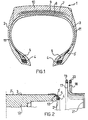
- FIG. 1 initially illustrates the type of tire which may specifically be made by the manufacturing method of the present invention; this tire comprises a torically-shaped carcass 2 comprising at least one reinforcing ply 3, the edges 3' of which are folded back in loop form around usual bead reinforcement wires 4.
- Rubber fillers 5 are arranged in a known manner between the ply 3 and the associated folded back edges 3'.
- the carcass may indifferently be either of the radial type or of the crossed-ply type.
- the tire 1 also comprises, crown-arranged around the carcass 2, a tread band 10 the ends of which are welded to the underlying carcass ply.
- a belt pack may be provided, consisting of at least two radially superimposed belt strips 7, 8, provided with parallel reinforcing cords in each strip and inclined with respect to the equatorial plane of the tire, preferably symmetrically crossed with one another and preferably reinforced by a further radially external layer 9 with circumferentially-oriented reinforcing cords. All the used materials are conventional and may be selected by the skilled in the art on the basis of specific needs with reference to the type of tire and its performance, so that they are not further described.
- the carcass is additionally provided with a pair of axially opposed sidewalls 11 extending in radial direction from the bead zone (from the bead wires) to cover the side ends of the tread band 10.
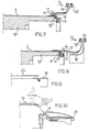
- FIG. 2 shows an assembly drum 12 also know as first-step drum, having a radially external cylindrical revolution surface, radially contractable for disengaging the carcass sleeve built on the drum.
- the drawing figures illustrating the different operating steps show partial cross sections, both axial and radial, of the assembly devices and of the tire being manufactured and do not illustrate the common frame, i.e. the apparatus, on which the above mentioned devices and the related acting means are mounted.
- the cylindrical surface of the assembly drum 12 is connected to the two axially external side surfaces, generally at right angles to the drum rotation axis through two curvilinear surfaces, also defined hereinbelow as drum shoulders, each preferably shaped according to an arc having radius "r".
- annular flange aside of each end of drum 12 is arranged an annular flange, preferably a pair 19, 20 of annular flanges, coaxial with the drum 12 and having an internal diameter greater than that of the drum, synchronously rotating and separately axially movable in both directions with respect thereto.
- Each flange is integral with one end of a tubular element 17, 18 free at the other end and is fixed to a means for axial movement.
- the tubular elements 17, 18 are coaxial and concentric with one another and comprise a geometrical figure identified by a tubular portion having a diameter substantially equal to the drum diameter, which at one end opens like a funnel to engage with one of the above mentioned flanges.
- the means for the axial movement of the flanges are not shown since they are of known type and in an case readily determinable by one skilled in the art: for example, they may consist of an apparatus with cylinder and piston with hydraulic or pneumatic control, having the function of displacing each flange and, along therewith, the related tubular element, either towards the assembly drum or towards the opposite direction.
- Each element has a tubular and funnel-like shape with unbroken surface and is made of an anti-adhesive material with elasticity characteristics in the circumferential direction but substantially inextensible in the axial direction, for the purpose of being able to expand for wrapping up, optionally under pressure if desired, cylindrical bodies placed therein and to withstand longitudinal traction without elongation.
- the aforementioned tubular elements are preferably made of rubber having anti-adhesive characteristics with respect to the materials of the tire carcass with which they will be in contact, e.g. with silicone-based rubber compositions, and preferably incorporate continuous or discontinuous reinforcement means arranged in such a way as to provide the above-mentioned circumferential extensibility and axial inextensibility.
- the anti-adhesive element is made of a cylinder of rubberized fabric, reinforced with threads selected from either textile or metallic monofilaments, elementary threads and cords mutually arranged in parallel with one another and essentially in accordance with the generating line of the cylinder.
- threads selected from either textile or metallic monofilaments, elementary threads and cords mutually arranged in parallel with one another and essentially in accordance with the generating line of the cylinder.
- the reinforcing elements may not be incorporated in the tubular element and in a different embodiment they can be present on one or both the surfaces of the tubular element, preferably also acting as anti-adhesive elements.
- the element may be made of a rubber tube incorporating as reinforcing elements, e.g. textile, metallic or glass fibers, preferably oriented in an axial direction, uniformly distributed in the tube wall.
- as reinforcing elements e.g. textile, metallic or glass fibers, preferably oriented in an axial direction, uniformly distributed in the tube wall.
- the thickness and/or quantity of said reinforcing means is determined as a function of the stresses to which the element might be subjected in operation and, more specifically, of the tensile stress to which it will undergo during the manufacturing steps of the carcass sleeve.
- FIG. 2 also shows the cylindrical carcass sleeve during its assembly on the drum 12 according to the procedures discussed above.
- a sheet of impermeable rubber 2' and at least one carcass ply 3, optionally preassembled together, are wrapped by rotating the drum onto the cylindrical drum surface;
- the impermeable sheet usually called 'liner', has the function of ensuring air tightness in the finished tire of the so-called tubeless type, i.e. those which are used without inner tubes.
- edges 3' of the ply 3 are folded back in loop form radially from the inside outwardly around the bead wire and its filling, preferably up to covering part of the carcass ply at the central cylindrical portion of the drum.
- bead zone may comprise other structural elements, such as loops, edges and additional reinforcements, all known per se, which are not described here bearing no influence with respect to the present invention.
- the strips of elastomeric material constituting the tire sidewalls are mounted on the cylindrical sleeve.
- the axially most inward flange 19 is axially moved along (FIG. 3) the direction of arrow F1, around the assembly drum thus dragging the tubular element 17 onto the carcass sleeve, continuing the movement at least until the axially external edge 21 of said element is also correctly positioned on the sleeve as explained below.
- the internal diameter of the tubular element is selected so as to have a value proximate to but not greater than that of the assembly drum diameter, the element slightly expands, point by point, in relation to the thickness of the sleeve fitted on the drum, which is variable from a minimum at the cylindrical portion of the carcass ply up to a maximum at the ply folds and thus wraps up the sleeve with a slight pressure.
- the expansion values of the element do not exceed 10% of its circumferential development.
- the above mentioned axial movement in relation to the length of the tubular element continues until the free end 21, i.e. the axially external edge of the element, reaches the connecting arc 14 between the cylindrical surface and the drum shoulders.
- the length of the cylindrical part of the tubular element i.e. of the tubular element part between the beginning of the funnel-shaped portion - connecting the element to the corresponding displacing flange - and the axially external edge, allows to use said tubular element with different widths of the tire sidewalls, in such a way that it does not require its substitution along with the size of the tire being built, as will be clarified hereinbelow.
- the position of the above mentioned edge 21 of the tubular element is identified by the intersection of the surface of the connecting arc 14 with the conical surface defined by the radius of said arc 14 when the angle a between the drum rotation axis and the radius, i.e. the cone opening, is between 0° and 90°.
- the angle a is between 15° and 60° and, still more preferably, is equal to 45° in such a manner that after overturning the arrangement of the sidewall aside of the drum keeps the same diameter value of its configuration upon deposition on the drum.
- the sidewall portion in direct contact with the carcass sleeve i.e. the sidewall portion between the axially external edge of the tubular element and the axially external edge of the sidewall, may have a so narrow width as not to ensure that rotation of the drum will drag out and wrap the sidewall strip thereon, especially when, in accordance with the above mentioned preferred embodiment of the present invention, the edge of the element lies on the end of the drum.
- the carcass sleeve is now ready to be removed from the drum and sent to the forming step after removal of the tubular element and spreading apart of the sidewall as discussed below.
- another operating step is provided which is carried out on the assembly drum using the second tubular element mentioned above.
- the second tubular element 18 is displaced, according to an axial movement along arrow F1 shown in FIG. 6, towards the assembly drum until it is fitted on the outer surface of the sidewall 11 which in this manner is clamped between the couple of tubular elements 17, 18.
- the means for axially moving the two tubular elements 17, 18 are operated simultaneously and axially towards the outside of the drum along the direction of arrow F2 shown in FIG. 7.
- the sidewall adheres to the sleeve only at the curvilinear connecting portion with the drum shoulders upon overturning it takes on an essentially cylindrical configuration having a diameter corresponding to that of the drum as shown in FIG. 8, i.e. it is arranged according to an essentially stable configuration because its elastic memory can do nothing but compell said sidewall to return to the configuration it had upon deposition on the drum, i.e. a cylindrical configuration which is in practice aside and coaxial with the drum surface.
- the carcass sleeve having spread-apart sidewalls thus formed is removed from the assembly drum after radial contraction of the same and transferred into the second-step operating area, preferably directly onto the second-step drum by means of a transferring apparatus 23 (FIG. 9) comprising adequate sleeve-supporting means known per se.
- inflatable side chambers 28 overturn the sidewalls 11 on the carcass and on the side portions of the tread band and it is clear that the cylindrical form of the sidewalls obtainable by the method of the present invention allows to carry out this overturning in an optimal manner, without causing undesired deformation or irregular stretching of the sidewall.
- the method of the present invention achieves the desired results.
- the tubular element although being made of a releasing material insensitive to the stickiness of the green materials of the carcass sleeve, cannot be removed from beneath the sidewall following the axial movement towards the outside of the guide flange, since the axially internal end of the sidewall does not offer sufficient mechanical resistance to constitute a constraining element around which the tubular element could slip while revolving around itself: in conclusion, the overturning of the tubular element consequently causes overturning of the sidewall.
- This overturning only allows expansion in a circumferential direction for the tubular element but does not involve elongation in an axial direction, which is prevented by the presence of the inextensible reinforcing elements of said element so that it ensures dimensional stability of the sidewall width, which sidewall cannot undergo stretching in the same direction in its overturning movement.
- the tubular element 18 acts as a lubricating substance with the result of allowing the sidewall 11 (FIG. 7) to freely slide towards the opening position shown in FIG. 8.
- the skilled in the art will have no difficulty in replacing the element 18, if preferred, with other alternative anti-adhesive means.
- the weld line position between the sidewall and the sleeve at the curvilinear connection between the cylindrical surface and the drum shoulders is also to be considered as preferred, since a different position, in particular an axially more inward one, does not preclude to carry out a correct spreading apart of the sidewall in a uniform manner and without irregular stretching of the material: on the other hand, the spread-apart sidewall being arranged along a surface having a diameter greater than that of deposition on the drum, maintains an internal tension state which tends to close the axially outermost free end towards the drum rotation axis.
- tubular elements employed in the steps of the present method allows, as explained above, to abandon the conventional anti-adhesive elements in sheet form inserted between the carcass ply and the sidewalls during the manufacturing steps of the carcass sleeve.
- tubular element being radially extensible, may be employed for a large range of sleeves of different diameter, thus avoiding the need to change frequently equipment for different tire sizes.
- tubular elements being already prepared in the correct form instead of being in sheet form, may be connected to automatic displacing devices capable to insert and withdraw the tubular elements into and from a cylindrically-shaped body within the same, such as a carcass sleeve wrapped on an assembly drum.
- the steps of applying the releasing and sidewall fold-back element may advantageously be automated with a number of qualitative and economic benefits for the production process.
- step of spreading apart the sidewall may be performed even after having disassembled the sleeve from the first-step drum by providing appropriate clamping and releasing means for the axially internal edge of the tubular elements from respective displacement flanges which allows to move the sleeve with the tubular elements still inserted therein.
- the method of the present invention allows to spread apart the sidewalls aside of the sleeve in a stable tubular form, substantially aligned with the assembly drum surface. Thanks to the above mentioned feature, the step of overturning the sidewalls performed on the forming drum against the toric carcass takes place correctly.
- the chambers 28 aside of the forming drum are positioned (FIG. 10) below the surface of the sidewalls arranged in a stable and extended tubular configuration, free from curlings or similar irregularities.
- the chambers may gradually and regularly act on the sidewalls pressing them against the wall of the carcass and of the tread band.
Landscapes
- Engineering & Computer Science (AREA)
- Mechanical Engineering (AREA)
- Tyre Moulding (AREA)
- Basic Packing Technique (AREA)
- Auxiliary Devices For And Details Of Packaging Control (AREA)
Claims (15)
- Verfahren zur Herstellung eines Reifens (1), der Seitenwandenden hat, die die Enden eines Laufflächenbandes (10) überlappen, wobei von einer zylindrischen hülsenförmigen Reifenkarkasse (2) mit wenigstens einer Karkassenlage (3), die mit Verstärkungskorden versehen ist, deren jeweilige Enden (3') um wenigstens einen in Umfangsrichtung nicht dehnbaren Wulstdraht (4) zurückgefaltet sind, und von einer Reifenseitenwand (11) ausgegangen wird, die an jedem Seitenabschnitt der Hülse festgelegt ist, und das Verfahren die Schritte aufweist:Herumlegen wenigstens einer Karkassenlage (3) um eine Montagetrommel (12) mit einer radial äußeren zylindrischen Fläche, die mit entsprechenden radial äußeren Seitenflächen über zwei gekrümmte Flächen (13) verbunden ist, wobei die Karkassenlage (3) eine Breite hat, die größer als die Breite der Trommel (12) ist,radial und einwärts Umschlagen der Ränder (3') der Lage (3) auf die Seitenflächen der Trommel (12),Befestigen der Wulstdrähte (4) an den Rändern (3') der Karkassenlage (3) an den Seitenflächen,Zurückfalten der Ränder (3') der Karkassenlage (3) in einer Schleifenform radial und nach außen um die Wulstdrähte (4) herum und an die Karkassenlage (3),Anordnen eines Antihaftelements (17) um Seitenabschnitte der Karkassenlage (3) an einem zylindrischen Abschnitt und für einen Teil einer vorher festgelegten Breite davon,Herumlegen der entsprechenden Seitenwand (11) des Reifens (1) um jedes Antihaftelement (17), wobei der axial innere Rand an dem Antihaftelement (17) und der axial äußere Rand bezüglich des entsprechenden axial äußeren Randes (21) des Antihaftelements (17) seitlich vorstehen,Pressen eines Teils der Seitenwand (11), der seitlich von dem axial äußeren Rand (21) des Antihaftelements (17) vorsteht, gegen den entsprechenden Lagenabschnitt und/oder gegen den zurückgefalteten Lagenabschnitt der Karkassenlage (3) undAbziehen der zylindrischen hülsenförmigen Karkasse (2) von der Montagetrommel (12) für weitere Endbearbeitungsvorgänge des Reifens (1),wobei sich das Verfahren dadurch auszeichnet, dass als Antihaftelement (17) ein erstes rohrförmiges Element (17) verwendet wird, das zur Trommel (12) koaxial ist, das radial dehnbar und axial nicht dehnbar ist und das axial in beiden Richtungen aus einer ersten Position weg von der Trommel (12) in eine zweite Position bewegbar ist, in der es auf diese passt.
- Verfahren nach Anspruch 1, dadurch gekennzeichnet, dass das erste rohrförmige Element (17) auf die Trommel (12) dadurch aufgepasst wird, dass ein axial freier äußerer Rand (21) des rohrförmigen Elements (17) an den gekrümmten Verbindungsflächen (13) zwischen die radial äußere zylindrische Fläche und die entsprechenden axial äußeren Flächen der Trommel (12) gebracht wird.
- Verfahren nach Anspruch 2, dadurch gekennzeichnet, dass der freie Rand (21) des ersten rohrförmigen Elements (17) an der Kreuzung zwischen die gekrümmte Verbindungsfläche (13) und die konische Fläche gebracht wird, die durch den Radius (r) der gekrümmten Fläche (13) erzeugt wird, die um die Drehachse der Trommel (12) dreht, wobei der Konus einen Öffnungswinkel (α) von 0° bis 90° hat.
- Verfahren nach Anspruch 3, dadurch gekennzeichnet, dass der Winkel (α) zwischen 15° und 60° liegt.
- Verfahren nach Anspruch 1, dadurch gekennzeichnet, dass es den zusätzlichen, vor dem Abziehen der Hülse von der Trommel (12) ausgeführten Schritt aufweist, den axial inneren Rand des ersten rohrförmigen Elements (17) axial und nach außen von der Karkasse (2) abzuziehen, bis die Seitenwände (11) ausgebreitet sind.
- Verfahren nach Anspruch 1, dadurch gekennzeichnet, dass als Antihafteinrichtung auf die Seitenwände (11) ein zweites rohrförmiges Element (18) aufgebracht wird, das radial dehnbar und in Längsrichtung nicht dehnbar ist, das koaxial zur Trommel (12) ist und das axial in beiden Richtungen aus einer Position weg von der Trommel (12) in eine zweite Position bewegbar ist, in der es auf diese passt.
- Verfahren nach Anspruch 1, dadurch gekennzeichnet, dass die Seitenwände (11) und das erste rohrförmige Element (17) miteinander zu einem Teil vereint werden, bevor die Trommel (12) gedreht wird, um das Herumlegen der Seitenwände (11) auf die hülsenförmige Karkasse (2) herbeizuführen.
- Vorrichtung zur Herstellung einer zylindrischen hülsenförmigen Reifenkarkasse (2) mit wenigstens einer Karkassenlage (3), die mit Verstärkungskorden versehen ist, deren jeweilige Enden (3') um wenigstens einen in Umfangsrichtung nicht dehnbaren Wulstdraht (4) zurückgefaltet sind, und mit einer Reifenseitenwand (11), die an jedem Seitenabschnitt der Hülse befestigt ist, wobei die Vorrichtung eine Montagetrommel (12), die um ihre eigene Achse dreht, und eine radial zusammenziehbare, radial äußere zylindrische Drehfläche hat, die mit zwei axial gegenüberliegenden äußeren Seitenflächen durch zwei gekrümmte Flächen (13) verbunden ist, Einrichtungen zum Umschlagen und Zurückfalten der Enden (3') der wenigstens einen Karkassenlage (3) auf die Seitenflächen und Einrichtungen zum Anlegen der Wulstdrähte (4) an die Seitenflächen aufweist, dadurch gekennzeichnet, dass die Vorrichtung seitlich von jeder Stirnseite der Trommel (12)wenigstens ein rohrförmiges Element (17), das einen rohrförmigen Teil mit einem Durchmesser hat, der nicht größer ist als der Durchmesser der Trommel, der koaxial zur Trommel (12) und der an einem Ende als Trichter offen ist,wenigstens einen ringförmigen Flansch (19), der koaxial zur Trommel (12) ist, einen Innendurchmesser hat, der größer ist als der Durchmesser der Trommel (12), der drehbar mit der Trommel (12) verbunden ist und der axial in beide Richtungen bezogen auf sie bewegbar ist, wobei der ringförmige Flansch (19) mit dem trichterförmigen Ende des Elements (17) verbunden ist, undEinrichtungen zum axialen Bewegen des wenigstens einen Flansches (19) aufweist.
- Vorrichtung nach Anspruch 8, dadurch gekennzeichnet, dass sie für jede Stirnseite der Trommel (12) ein Paar von rohrförmigen Elementen (17, 18) aufweist, von denen jedes mit einem entsprechenden ringförmigen Flansch (19, 20) verbunden ist.
- Vorrichtung nach Anspruch 9, dadurch gekennzeichnet, dass jedes Element (17, 18), das eine trichterförmige Rohrform und eine nicht unterbrochene Oberfläche hat, aus einem entlastenden Material hergestellt ist, das in Umfangsrichtung dehnbar und in Axialrichtung nicht dehnbar ist.
- Vorrichtung nach Anspruch 10, dadurch gekennzeichnet, dass das entlastende Material eine Kautschukzusammensetzung auf Silikonbasis ist.
- Vorrichtung nach Anspruch 10, dadurch gekennzeichnet, dass die rohrförmigen Elemente (17, 18) Verstärkungseinrichtungen aus entlastendem Material aufweisen, die auf wenigstens einer Fläche der rohrförmigen Elemente (17, 18) angeordnet sind.
- Vorrichtung nach Anspruch 10, dadurch gekennzeichnet, dass die rohrförmigen Elemente (17, 18) Verstärkungseinrichtungen aufweisen, die so angeordnet sind, dass sie die Dehnbarkeit in Umfangsrichtung und die Nichtdehnbarkeit in Axialrichtung bereitstellen.
- Vorrichtung nach Anspruch 13, dadurch gekennzeichnet, dass die rohrförmigen Elemente (17, 18) aus einem gummierten Gewebezylinder hergestellt sind, der mit Fäden verstärkt ist, die aus der Gruppe ausgewählt sind, die Monofilamente, Elementarfäden und Verstärkungskorde entweder textil oder metallisch umfasst, und die zueinander parallel entsprechend der Erzeugendendes Zylinders angeordnet sind.
- Vorrichtung nach Anspruch 13, dadurch gekennzeichnet, dass die rohrförmigen Elemente (17, 18) aus einem Kautschukrohr hergestellt sind, in dem Verstärkungsfasern eingeschlossen sind, die aus der Gruppe ausgewählt sind, die axial ausgerichtete Textil-, Metall- oder Glasfasern umfasst.
Applications Claiming Priority (2)
| Application Number | Priority Date | Filing Date | Title |
|---|---|---|---|
| ITMI961650 | 1996-07-31 | ||
| IT96MI001650A IT1283382B1 (it) | 1996-07-31 | 1996-07-31 | Metodo e dispositivo per confezionare un pneumatico con le estremita' dei fianchi sovrapposte alle estremita' della fascia |
Publications (2)
| Publication Number | Publication Date |
|---|---|
| EP0822059A1 EP0822059A1 (de) | 1998-02-04 |
| EP0822059B1 true EP0822059B1 (de) | 2002-03-06 |
Family
ID=11374730
Family Applications (1)
| Application Number | Title | Priority Date | Filing Date |
|---|---|---|---|
| EP97202114A Expired - Lifetime EP0822059B1 (de) | 1996-07-31 | 1997-07-29 | Verfahren und Vorrichtung zur Herstellung eines Reifens mit seinen Seitenwänden die die Laufflächenseiten überlappen |
Country Status (11)
| Country | Link |
|---|---|
| US (2) | US5851329A (de) |
| EP (1) | EP0822059B1 (de) |
| JP (1) | JPH1095053A (de) |
| AR (1) | AR008130A1 (de) |
| AT (1) | ATE213993T1 (de) |
| BR (1) | BR9704143A (de) |
| DE (1) | DE69710823T2 (de) |
| ES (1) | ES2174178T3 (de) |
| IT (1) | IT1283382B1 (de) |
| PT (1) | PT822059E (de) |
| TR (1) | TR199700717A2 (de) |
Families Citing this family (4)
| Publication number | Priority date | Publication date | Assignee | Title |
|---|---|---|---|---|
| US6783618B2 (en) | 2000-12-22 | 2004-08-31 | Pirelli Pneumatici S.P.A. | Method and apparatus for the manufacturing of a tire for vehicle wheels |
| AU2002343129A1 (en) * | 2002-10-28 | 2004-05-13 | Pirelli Pneumatici S.P.A. | Method and apparatus for manufacturing a pneumatic tyre for vehicle wheels |
| DE60210682T2 (de) * | 2002-10-28 | 2007-03-29 | Pirelli Pneumatici S.P.A. | Verfahren und vorrichtung zur herstellung eines fahrzeugreifens |
| JP5358681B2 (ja) | 2008-05-28 | 2013-12-04 | ピレリ・タイヤ・ソチエタ・ペル・アツィオーニ | タイヤを構築する方法および装置 |
Family Cites Families (10)
| Publication number | Priority date | Publication date | Assignee | Title |
|---|---|---|---|---|
| US3728194A (en) * | 1970-11-27 | 1973-04-17 | Nrm Corp | Rotating expandable ply ring mechanism |
| US4006766A (en) * | 1970-12-29 | 1977-02-08 | Bridgestone Tire Company Limited | Radial tires |
| GB1593761A (en) * | 1977-01-11 | 1981-07-22 | Dunlop Ltd | Pneumatic tyres |
| JPS5842444A (ja) * | 1981-09-08 | 1983-03-11 | Bridgestone Corp | タイヤ成形方法 |
| GB2195959B (en) * | 1986-09-24 | 1990-04-04 | Apsley Metals Ltd | Tyre building apparatus |
| JP2519069B2 (ja) * | 1987-10-06 | 1996-07-31 | 株式会社ブリヂストン | タイヤ成形装置 |
| GB8809647D0 (en) * | 1988-04-23 | 1988-05-25 | Apsley Metals Ltd | Method of manufacture of tyre & apparatus therefor |
| JP2707285B2 (ja) * | 1988-09-06 | 1998-01-28 | 株式会社ブリヂストン | タイヤ構成部材の搬送装置 |
| EP0613767B1 (de) * | 1993-03-04 | 1998-06-10 | Bridgestone Corporation | Verfahren zum Aufbauen von Rohreifen |
| DE69514563T2 (de) * | 1994-04-12 | 2000-08-03 | Bridgestone Corp., Tokio/Tokyo | Verfahren zur Herstellung von radialen Rohreifen mit niedrigem Querschnittsprofil |
-
1996
- 1996-07-31 IT IT96MI001650A patent/IT1283382B1/it active IP Right Grant
-
1997
- 1997-07-23 US US08/899,267 patent/US5851329A/en not_active Expired - Fee Related
- 1997-07-29 DE DE69710823T patent/DE69710823T2/de not_active Expired - Lifetime
- 1997-07-29 EP EP97202114A patent/EP0822059B1/de not_active Expired - Lifetime
- 1997-07-29 PT PT97202114T patent/PT822059E/pt unknown
- 1997-07-29 AT AT97202114T patent/ATE213993T1/de not_active IP Right Cessation
- 1997-07-29 ES ES97202114T patent/ES2174178T3/es not_active Expired - Lifetime
- 1997-07-30 BR BR9704143-2A patent/BR9704143A/pt not_active IP Right Cessation
- 1997-07-31 AR ARP970103468A patent/AR008130A1/es active IP Right Grant
- 1997-07-31 JP JP9206233A patent/JPH1095053A/ja active Pending
- 1997-07-31 TR TR97/00717A patent/TR199700717A2/xx unknown
-
1998
- 1998-09-11 US US09/151,700 patent/US6098686A/en not_active Expired - Fee Related
Also Published As
| Publication number | Publication date |
|---|---|
| JPH1095053A (ja) | 1998-04-14 |
| US5851329A (en) | 1998-12-22 |
| ATE213993T1 (de) | 2002-03-15 |
| DE69710823D1 (de) | 2002-04-11 |
| TR199700717A2 (xx) | 1998-02-21 |
| ITMI961650A0 (de) | 1996-07-31 |
| ITMI961650A1 (it) | 1998-01-31 |
| PT822059E (pt) | 2002-07-31 |
| EP0822059A1 (de) | 1998-02-04 |
| BR9704143A (pt) | 2000-12-19 |
| DE69710823T2 (de) | 2002-11-21 |
| ES2174178T3 (es) | 2002-11-01 |
| US6098686A (en) | 2000-08-08 |
| IT1283382B1 (it) | 1998-04-17 |
| AR008130A1 (es) | 1999-12-09 |
Similar Documents
| Publication | Publication Date | Title |
|---|---|---|
| RU2222437C2 (ru) | Шина для колес транспортного средства | |
| EP0647522B1 (de) | Verfahren und Vorrichtung zum Wickeln einer Beschichtungsstruktur um den Wulstring herum in Fahrzeugreifen | |
| EP2276627B1 (de) | Verfahren und vorrichtung zur reifenherstellung | |
| EP0468738A2 (de) | Verfahren und Gürtelbildungstrommel zum Aufbau eines Rohreifens | |
| CA1069423A (en) | Method and apparatus for building a closed torus tire | |
| EP1216814B1 (de) | Verfahren und Vorrichtung zur Herstellung von Luftreifen für Fahrzeugräder | |
| US5851329A (en) | Method for manufacturing a tire having the sidewalls ends overlapping the ends of the tread band | |
| EP0053997B1 (de) | Luftreifen und Verfahren zu seiner Herstellung | |
| EP3562661B1 (de) | Vorrichtung und verfahren zur herstellung von reifen für fahrzeugräder | |
| EP1136243B1 (de) | Verfahren zur Herstellung von Luftreifen | |
| US3816202A (en) | Tire building method and machine | |
| US6783618B2 (en) | Method and apparatus for the manufacturing of a tire for vehicle wheels | |
| EP0302935B1 (de) | Radialreifen für flugzeug und dessen herstellung | |
| JPH03118144A (ja) | 空気入りタイヤとその製造方法 | |
| EP0894614B1 (de) | Verfahren zur Herstellung eines Luftreifens für Fahrzeugräder | |
| RU2373056C2 (ru) | Способ и устройство для изготовления шин для колес транспортных средств | |
| JPS599340B2 (ja) | ラジアルタイヤの成形方法 | |
| JPH0647274B2 (ja) | 航空機用ラジアルタイヤの製造方法 | |
| EP1556207B1 (de) | Verfahren und vorrichtung zur herstellung eines fahrzeugreifens | |
| JP2691459B2 (ja) | 空気入りタイヤの製造方法 | |
| US20060137807A1 (en) | Method and apparatus for manufacturing a pneumatic tyre for vehicle wheels | |
| WO2025032403A1 (en) | Process and apparatus for making multilayer annular components in building of tyres for vehicles | |
| JPH11165359A5 (de) | ||
| KR20050083818A (ko) | 차륜용 공기압 타이어 제조방법 및 제조장치 | |
| KR20050083817A (ko) | 차륜용 공기압 타이어 제조방법 및 제조장치 |
Legal Events
| Date | Code | Title | Description |
|---|---|---|---|
| PUAI | Public reference made under article 153(3) epc to a published international application that has entered the european phase |
Free format text: ORIGINAL CODE: 0009012 |
|
| AK | Designated contracting states |
Kind code of ref document: A1 Designated state(s): AT BE DE DK ES FR GB GR IT LU NL PT SE |
|
| 17P | Request for examination filed |
Effective date: 19980707 |
|
| AKX | Designation fees paid |
Free format text: AT BE DE DK ES FR GB GR IT LU NL PT SE |
|
| RBV | Designated contracting states (corrected) |
Designated state(s): AT BE DE DK ES FR GB GR IT LU NL PT SE |
|
| RAP1 | Party data changed (applicant data changed or rights of an application transferred) |
Owner name: PIRELLI PNEUMATICI SOCIETA' PER AZIONI |
|
| 17Q | First examination report despatched |
Effective date: 20000204 |
|
| GRAG | Despatch of communication of intention to grant |
Free format text: ORIGINAL CODE: EPIDOS AGRA |
|
| GRAG | Despatch of communication of intention to grant |
Free format text: ORIGINAL CODE: EPIDOS AGRA |
|
| GRAG | Despatch of communication of intention to grant |
Free format text: ORIGINAL CODE: EPIDOS AGRA |
|
| GRAH | Despatch of communication of intention to grant a patent |
Free format text: ORIGINAL CODE: EPIDOS IGRA |
|
| GRAH | Despatch of communication of intention to grant a patent |
Free format text: ORIGINAL CODE: EPIDOS IGRA |
|
| REG | Reference to a national code |
Ref country code: GB Ref legal event code: IF02 |
|
| GRAA | (expected) grant |
Free format text: ORIGINAL CODE: 0009210 |
|
| AK | Designated contracting states |
Kind code of ref document: B1 Designated state(s): AT BE DE DK ES FR GB GR IT LU NL PT SE |
|
| PG25 | Lapsed in a contracting state [announced via postgrant information from national office to epo] |
Ref country code: NL Free format text: LAPSE BECAUSE OF FAILURE TO SUBMIT A TRANSLATION OF THE DESCRIPTION OR TO PAY THE FEE WITHIN THE PRESCRIBED TIME-LIMIT Effective date: 20020306 Ref country code: GR Free format text: LAPSE BECAUSE OF FAILURE TO SUBMIT A TRANSLATION OF THE DESCRIPTION OR TO PAY THE FEE WITHIN THE PRESCRIBED TIME-LIMIT Effective date: 20020306 Ref country code: BE Free format text: LAPSE BECAUSE OF FAILURE TO SUBMIT A TRANSLATION OF THE DESCRIPTION OR TO PAY THE FEE WITHIN THE PRESCRIBED TIME-LIMIT Effective date: 20020306 Ref country code: AT Free format text: LAPSE BECAUSE OF FAILURE TO SUBMIT A TRANSLATION OF THE DESCRIPTION OR TO PAY THE FEE WITHIN THE PRESCRIBED TIME-LIMIT Effective date: 20020306 |
|
| REF | Corresponds to: |
Ref document number: 213993 Country of ref document: AT Date of ref document: 20020315 Kind code of ref document: T |
|
| REF | Corresponds to: |
Ref document number: 69710823 Country of ref document: DE Date of ref document: 20020411 |
|
| PG25 | Lapsed in a contracting state [announced via postgrant information from national office to epo] |
Ref country code: SE Free format text: LAPSE BECAUSE OF FAILURE TO SUBMIT A TRANSLATION OF THE DESCRIPTION OR TO PAY THE FEE WITHIN THE PRESCRIBED TIME-LIMIT Effective date: 20020606 Ref country code: DK Free format text: LAPSE BECAUSE OF FAILURE TO SUBMIT A TRANSLATION OF THE DESCRIPTION OR TO PAY THE FEE WITHIN THE PRESCRIBED TIME-LIMIT Effective date: 20020606 |
|
| PG25 | Lapsed in a contracting state [announced via postgrant information from national office to epo] |
Ref country code: LU Free format text: LAPSE BECAUSE OF NON-PAYMENT OF DUE FEES Effective date: 20020729 |
|
| REG | Reference to a national code |
Ref country code: PT Ref legal event code: SC4A Free format text: AVAILABILITY OF NATIONAL TRANSLATION Effective date: 20020416 |
|
| NLV1 | Nl: lapsed or annulled due to failure to fulfill the requirements of art. 29p and 29m of the patents act | ||
| ET | Fr: translation filed | ||
| REG | Reference to a national code |
Ref country code: ES Ref legal event code: FG2A Ref document number: 2174178 Country of ref document: ES Kind code of ref document: T3 |
|
| PLBE | No opposition filed within time limit |
Free format text: ORIGINAL CODE: 0009261 |
|
| STAA | Information on the status of an ep patent application or granted ep patent |
Free format text: STATUS: NO OPPOSITION FILED WITHIN TIME LIMIT |
|
| 26N | No opposition filed |
Effective date: 20021209 |
|
| PGFP | Annual fee paid to national office [announced via postgrant information from national office to epo] |
Ref country code: FR Payment date: 20060717 Year of fee payment: 10 |
|
| PGFP | Annual fee paid to national office [announced via postgrant information from national office to epo] |
Ref country code: GB Payment date: 20060726 Year of fee payment: 10 |
|
| GBPC | Gb: european patent ceased through non-payment of renewal fee |
Effective date: 20070729 |
|
| PG25 | Lapsed in a contracting state [announced via postgrant information from national office to epo] |
Ref country code: GB Free format text: LAPSE BECAUSE OF NON-PAYMENT OF DUE FEES Effective date: 20070729 |
|
| REG | Reference to a national code |
Ref country code: FR Ref legal event code: ST Effective date: 20080331 |
|
| PG25 | Lapsed in a contracting state [announced via postgrant information from national office to epo] |
Ref country code: FR Free format text: LAPSE BECAUSE OF NON-PAYMENT OF DUE FEES Effective date: 20070731 |
|
| PGFP | Annual fee paid to national office [announced via postgrant information from national office to epo] |
Ref country code: PT Payment date: 20080708 Year of fee payment: 12 |
|
| REG | Reference to a national code |
Ref country code: PT Ref legal event code: MM4A Free format text: LAPSE DUE TO NON-PAYMENT OF FEES Effective date: 20100129 |
|
| PG25 | Lapsed in a contracting state [announced via postgrant information from national office to epo] |
Ref country code: PT Free format text: LAPSE BECAUSE OF NON-PAYMENT OF DUE FEES Effective date: 20100129 |
|
| PGFP | Annual fee paid to national office [announced via postgrant information from national office to epo] |
Ref country code: DE Payment date: 20160726 Year of fee payment: 20 Ref country code: IT Payment date: 20160722 Year of fee payment: 20 |
|
| PGFP | Annual fee paid to national office [announced via postgrant information from national office to epo] |
Ref country code: ES Payment date: 20160726 Year of fee payment: 20 |
|
| REG | Reference to a national code |
Ref country code: DE Ref legal event code: R071 Ref document number: 69710823 Country of ref document: DE |
|
| REG | Reference to a national code |
Ref country code: ES Ref legal event code: FD2A Effective date: 20180508 |
|
| PG25 | Lapsed in a contracting state [announced via postgrant information from national office to epo] |
Ref country code: ES Free format text: LAPSE BECAUSE OF EXPIRATION OF PROTECTION Effective date: 20170730 |