EP0822402A2 - Méthode de conditionnement d'un débit de gaz de mesure - Google Patents
Méthode de conditionnement d'un débit de gaz de mesure Download PDFInfo
- Publication number
- EP0822402A2 EP0822402A2 EP97113001A EP97113001A EP0822402A2 EP 0822402 A2 EP0822402 A2 EP 0822402A2 EP 97113001 A EP97113001 A EP 97113001A EP 97113001 A EP97113001 A EP 97113001A EP 0822402 A2 EP0822402 A2 EP 0822402A2
- Authority
- EP
- European Patent Office
- Prior art keywords
- sample gas
- hose
- gas
- condensate
- flow
- Prior art date
- Legal status (The legal status is an assumption and is not a legal conclusion. Google has not performed a legal analysis and makes no representation as to the accuracy of the status listed.)
- Granted
Links
Images
Classifications
-
- G—PHYSICS
- G01—MEASURING; TESTING
- G01N—INVESTIGATING OR ANALYSING MATERIALS BY DETERMINING THEIR CHEMICAL OR PHYSICAL PROPERTIES
- G01N1/00—Sampling; Preparing specimens for investigation
- G01N1/02—Devices for withdrawing samples
- G01N1/22—Devices for withdrawing samples in the gaseous state
- G01N1/24—Suction devices
-
- G—PHYSICS
- G01—MEASURING; TESTING
- G01N—INVESTIGATING OR ANALYSING MATERIALS BY DETERMINING THEIR CHEMICAL OR PHYSICAL PROPERTIES
- G01N33/00—Investigating or analysing materials by specific methods not covered by groups G01N1/00 - G01N31/00
- G01N33/0004—Gaseous mixtures, e.g. polluted air
- G01N33/0009—General constructional details of gas analysers, e.g. portable test equipment
- G01N33/0011—Sample conditioning
- G01N33/0016—Sample conditioning by regulating a physical variable, e.g. pressure or temperature
-
- G—PHYSICS
- G01—MEASURING; TESTING
- G01N—INVESTIGATING OR ANALYSING MATERIALS BY DETERMINING THEIR CHEMICAL OR PHYSICAL PROPERTIES
- G01N1/00—Sampling; Preparing specimens for investigation
- G01N1/02—Devices for withdrawing samples
- G01N1/22—Devices for withdrawing samples in the gaseous state
- G01N2001/2282—Devices for withdrawing samples in the gaseous state with cooling means
-
- G—PHYSICS
- G01—MEASURING; TESTING
- G01N—INVESTIGATING OR ANALYSING MATERIALS BY DETERMINING THEIR CHEMICAL OR PHYSICAL PROPERTIES
- G01N33/00—Investigating or analysing materials by specific methods not covered by groups G01N1/00 - G01N31/00
- G01N33/0004—Gaseous mixtures, e.g. polluted air
- G01N33/0009—General constructional details of gas analysers, e.g. portable test equipment
- G01N33/0027—General constructional details of gas analysers, e.g. portable test equipment concerning the detector
- G01N33/0036—General constructional details of gas analysers, e.g. portable test equipment concerning the detector specially adapted to detect a particular component
- G01N33/0037—NOx
-
- G—PHYSICS
- G01—MEASURING; TESTING
- G01N—INVESTIGATING OR ANALYSING MATERIALS BY DETERMINING THEIR CHEMICAL OR PHYSICAL PROPERTIES
- G01N33/00—Investigating or analysing materials by specific methods not covered by groups G01N1/00 - G01N31/00
- G01N33/0004—Gaseous mixtures, e.g. polluted air
- G01N33/0009—General constructional details of gas analysers, e.g. portable test equipment
- G01N33/0027—General constructional details of gas analysers, e.g. portable test equipment concerning the detector
- G01N33/0036—General constructional details of gas analysers, e.g. portable test equipment concerning the detector specially adapted to detect a particular component
- G01N33/0042—SO2 or SO3
-
- Y—GENERAL TAGGING OF NEW TECHNOLOGICAL DEVELOPMENTS; GENERAL TAGGING OF CROSS-SECTIONAL TECHNOLOGIES SPANNING OVER SEVERAL SECTIONS OF THE IPC; TECHNICAL SUBJECTS COVERED BY FORMER USPC CROSS-REFERENCE ART COLLECTIONS [XRACs] AND DIGESTS
- Y02—TECHNOLOGIES OR APPLICATIONS FOR MITIGATION OR ADAPTATION AGAINST CLIMATE CHANGE
- Y02A—TECHNOLOGIES FOR ADAPTATION TO CLIMATE CHANGE
- Y02A50/00—TECHNOLOGIES FOR ADAPTATION TO CLIMATE CHANGE in human health protection, e.g. against extreme weather
- Y02A50/20—Air quality improvement or preservation, e.g. vehicle emission control or emission reduction by using catalytic converters
Definitions
- the invention relates to a method for processing a Sample gas flow for a gas analysis device according to the preamble of claim 1.
- the sample gas especially the one contained in the sample gas To remove moisture.
- the invention was therefore based on the problem at the outset described method for processing a sample gas so improve that it no longer has the disadvantages described having.
- the preparation required Energy needs can be cut to last longer Operating times of battery-operated gas analysis devices too increase.
- the invention is based on the idea of completely dispensing with heating of the sample gas hose and largely preventing absorption of NO 2 and SO 2, for example, by considerably reducing the length of time the sample gas stays in the sample gas hose.
- This concept points in exactly the opposite direction to the efforts of experts known to date. So far, attempts have been made to reduce the energy required for heating the sample gas hose by providing the sample gas hose with an insulating jacket in order at least to minimize the heat dissipation to the outside. This led to sometimes unwieldy and heavy sample gas hoses.
- the method according to the invention allows the use of a thin measuring gas hose which does not require any additional elements, such as insulation or the like.
- sample gas hose serves as a cooling section for the sample gas that is passed through, so that with a corresponding design at the end of the sample gas hose a temperature has already been reached which essentially corresponds to the ambient temperature.
- This also reduces the cooling capacity required for the remaining cooling of the measuring gas to a temperature below the dew point temperature, which must be introduced by the cooling element integrated in the condensate separator.
- a temperature reduction in the condensate separator by 200 ° to 300 ° C had to be achieved only a temperature reduction of approximately 20 ° C is now required.
- This comparatively low cooling capacity can also be introduced over a considerably reduced distance, with the consequence that the condensate separator can be significantly reduced.
- the described effect is achieved when the mean flow velocity of the sample gas flow, ie the mean flow velocity averaged over the flow cross section, assumes a value of at least 1.5 m / s.
- Optimal results are achieved when the flow velocity is set to a value in the range between 4.0 m / s and 7.0 m / s.
- the measurement error caused by the absorption of NO 2 and SO 2 can be reduced to negligible values if the average residence time of the sample gas flow in the sample gas hose is less than 3 seconds.
- a measurement error of less than one percent can be achieved if, according to a preferred method variant, the dwell time is in the range from 0.25 seconds to 1.0 seconds.
- sample gas hose which is made of PTFE.
- This material is on the one hand sufficiently resistant to aggressive components of the measuring gas, on the other hand it has a surface structure, the adherence of droplets of condensate difficult, so that it is particularly easily carried away by the sample gas flow will.
- a measuring gas hose with an inner diameter in the range from 1.5 mm to 4.0 mm is preferably used, and an inner diameter of 2.0 mm has proven to be optimal.
- the above diameter specifications are matched to the measurement tasks described above in the field of exhaust technology and also take into account the normally installed delivery capacity of the sample gas pump, which sucks the sample gas stream out of the exhaust gas stream. This output allows a delivery volume of approx. 0.9 l / min. Taking into account the average state data of the sample gas and the flow resistances, the speed condition for the sample gas flow described at the beginning is obtained.
- a diameter of less than 1.0 mm leads in practice to such large flow resistances that the installed pump capacity is no longer sufficient.
- With an inner diameter of more than 4.0 mm however, the flow velocity in the sample gas hose has already dropped so far that measurement errors due to increased absorption of NO 2 and SO 2 occur to a measurement-relevant extent.
- a very particularly preferred process variant provides a condensate separator with an integrated Peltier element to use, the cold side of the Peltier element is directly flowed around by the sample gas stream.
- a condensate separator is filed on the same filing date Patent application No. (tes200 "condensate separator"), to which reference is expressly made.
- a condensate separator has one compared to now known condensate separators significantly better efficiency, so that the total energy requirement for processing of the sample gas can be reduced to an exceptionally high degree.
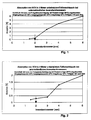
- FIG. 1 shows the absorption of NO 2 as a function of the inner diameter. After an initially flat increase in absorption from 0.2% to 0.4% during the transition from an inner diameter of 1.5 mm to 2 mm, the course of the curve increases relatively steeply and only weakens again towards large diameter values until it finally reached a value of 6% with a diameter of 6 mm.
- the largest of the given diameters (6 mm) corresponds to that Diameter of the sample gas lines previously used and clarified the potential for improvement of the invention Procedure. This measuring point also clarifies that with measuring hoses with currently usual diameters heating is unavoidable since an absorption of 6% is not is acceptable.
- the diagram shown in FIG. 2 shows the absorption of SO 2 as a function of the above-mentioned diameter.
- the curve shows a flat course in the range from 1.5 mm to 3 mm with absorption values between 0.2% and 0.4%. The curve rises very sharply towards larger diameters and achieves an absorption of 2% with the largest diameter.
- 2 mm inner diameter are favorable with regard to the absorption of SO to approximately 3 minutes.
- an inner diameter of approx. 2 mm represents the optimum.
- Hose is suitable for the accumulation of condensate droplets to be avoided safely on the inner wall.
- a Accumulation of such droplets to the so-called water sack which the sample gas would have to be passed through can no longer arise.
- the sample gas hose is thus independent of the position, i.e. it can be in any desired arrangement, for example also sagging or in an overhead arrangement, be used.
- test gas hose tested is not very sensitive to dirt. While one of the endurance tests carried out over two days was one interim cleaning not required. So that shows the practicality of the inventive concept.
Landscapes
- Chemical & Material Sciences (AREA)
- Life Sciences & Earth Sciences (AREA)
- Health & Medical Sciences (AREA)
- Engineering & Computer Science (AREA)
- Pathology (AREA)
- Immunology (AREA)
- Physics & Mathematics (AREA)
- Analytical Chemistry (AREA)
- Biochemistry (AREA)
- General Health & Medical Sciences (AREA)
- General Physics & Mathematics (AREA)
- Molecular Biology (AREA)
- Biomedical Technology (AREA)
- Combustion & Propulsion (AREA)
- Food Science & Technology (AREA)
- Medicinal Chemistry (AREA)
- Sampling And Sample Adjustment (AREA)
- Measuring Volume Flow (AREA)
- Transition And Organic Metals Composition Catalysts For Addition Polymerization (AREA)
Applications Claiming Priority (2)
| Application Number | Priority Date | Filing Date | Title |
|---|---|---|---|
| DE19631002 | 1996-08-01 | ||
| DE19631002A DE19631002C2 (de) | 1996-08-01 | 1996-08-01 | Meßgasschlauch für eine Gasanalyseeinrichtung |
Publications (3)
| Publication Number | Publication Date |
|---|---|
| EP0822402A2 true EP0822402A2 (fr) | 1998-02-04 |
| EP0822402A3 EP0822402A3 (fr) | 1999-02-03 |
| EP0822402B1 EP0822402B1 (fr) | 2000-10-25 |
Family
ID=7801438
Family Applications (1)
| Application Number | Title | Priority Date | Filing Date |
|---|---|---|---|
| EP97113001A Expired - Lifetime EP0822402B1 (fr) | 1996-08-01 | 1997-07-29 | Méthode de conditionnement d'un débit de gaz de mesure |
Country Status (6)
| Country | Link |
|---|---|
| US (1) | US5872305A (fr) |
| EP (1) | EP0822402B1 (fr) |
| JP (1) | JP3025806B2 (fr) |
| AT (1) | ATE197191T1 (fr) |
| DE (2) | DE19631002C2 (fr) |
| ES (1) | ES2152062T3 (fr) |
Cited By (1)
| Publication number | Priority date | Publication date | Assignee | Title |
|---|---|---|---|---|
| EP2533029A1 (fr) * | 2011-06-10 | 2012-12-12 | AVL List GmbH | Procédé et dispositif d'analyse des gaz d'échappement de moteurs à combustion interne, ainsi que refroidisseur de gaz d'échappement pour ce dispositif |
Families Citing this family (3)
| Publication number | Priority date | Publication date | Assignee | Title |
|---|---|---|---|---|
| US6825418B1 (en) | 2000-05-16 | 2004-11-30 | Wpfy, Inc. | Indicia-coded electrical cable |
| KR100631477B1 (ko) * | 2004-11-03 | 2006-10-09 | 건국대학교 산학협력단 | 대기오염 분석을 위한 수분 전처리 수단이 구비된 시료포집장치 |
| KR20110063442A (ko) | 2008-09-03 | 2011-06-10 | 테스토 아게 | 측정값 감지 및 측정값 표시를 위한 방법 |
Family Cites Families (13)
| Publication number | Priority date | Publication date | Assignee | Title |
|---|---|---|---|---|
| US3593023A (en) * | 1968-09-18 | 1971-07-13 | Beckman Instruments Inc | Apparatus and method for exhaust analysis |
| FR2346707A1 (fr) * | 1976-04-02 | 1977-10-28 | Commissariat Energie Atomique | Canne de prelevement de gaz corrosifs ou de fumees dans un four d'incineration |
| FR2578325B1 (fr) * | 1985-03-04 | 1987-03-20 | Siderurgie Fse Inst Rech | Ligne de prelevement et de conditionnement de gaz en vue de son analyse. |
| JPS62277536A (ja) * | 1986-05-27 | 1987-12-02 | Babcock Hitachi Kk | 排ガス自動サンプリング装置 |
| US4817441A (en) * | 1988-05-02 | 1989-04-04 | O'donnell & Associates, Inc. | Process and apparatus for obtaining a gas sample |
| US4974453A (en) * | 1989-10-19 | 1990-12-04 | United States Department Of Energy | Method and apparatus for nitrogen oxide determination |
| EP0554327A1 (fr) * | 1990-10-22 | 1993-08-11 | Marine Shale Processors, Inc. | Systeme de controle continu d'emissions base sur un spectrometre de masse servant a mesurer des gaz de musees dangereux |
| DE4100363A1 (de) * | 1991-01-04 | 1992-07-09 | Ver Kraftwerks Ag Peitz Nieder | Anordnung einer rauchgas-probenahme- und -analysen-vorrichtung fuer eine feuerung |
| JPH04315027A (ja) * | 1991-04-12 | 1992-11-06 | Babcock Hitachi Kk | 燃焼排ガス分析装置 |
| DE4308191C2 (de) * | 1992-03-21 | 1995-09-28 | Horiba Ltd | Gasanalysegerät |
| JP2541419B2 (ja) * | 1992-03-30 | 1996-10-09 | 株式会社島津製作所 | 燃焼排ガス測定装置 |
| DE4216404A1 (de) * | 1992-05-18 | 1993-11-25 | Testoterm Mestechnik Gmbh & Co | Gasentnahmevorrichtung für ein Rauchgas-Analysegerät |
| US5410907A (en) * | 1993-08-25 | 1995-05-02 | White Consolidated Ind Inc | Gas sampling method and dilution tunnel therefor |
-
1996
- 1996-08-01 DE DE19631002A patent/DE19631002C2/de not_active Revoked
-
1997
- 1997-07-29 AT AT97113001T patent/ATE197191T1/de not_active IP Right Cessation
- 1997-07-29 EP EP97113001A patent/EP0822402B1/fr not_active Expired - Lifetime
- 1997-07-29 DE DE59702521T patent/DE59702521D1/de not_active Expired - Fee Related
- 1997-07-29 ES ES97113001T patent/ES2152062T3/es not_active Expired - Lifetime
- 1997-08-01 JP JP9207835A patent/JP3025806B2/ja not_active Expired - Fee Related
- 1997-08-01 US US08/904,806 patent/US5872305A/en not_active Expired - Fee Related
Cited By (1)
| Publication number | Priority date | Publication date | Assignee | Title |
|---|---|---|---|---|
| EP2533029A1 (fr) * | 2011-06-10 | 2012-12-12 | AVL List GmbH | Procédé et dispositif d'analyse des gaz d'échappement de moteurs à combustion interne, ainsi que refroidisseur de gaz d'échappement pour ce dispositif |
Also Published As
| Publication number | Publication date |
|---|---|
| ATE197191T1 (de) | 2000-11-15 |
| DE59702521D1 (de) | 2000-11-30 |
| US5872305A (en) | 1999-02-16 |
| ES2152062T3 (es) | 2001-01-16 |
| JPH1082724A (ja) | 1998-03-31 |
| DE19631002A1 (de) | 1998-02-05 |
| EP0822402A3 (fr) | 1999-02-03 |
| JP3025806B2 (ja) | 2000-03-27 |
| DE19631002C2 (de) | 1998-07-16 |
| EP0822402B1 (fr) | 2000-10-25 |
Similar Documents
| Publication | Publication Date | Title |
|---|---|---|
| DE60303426T2 (de) | Thermischer Sensor zur Erkennung von Vereisungsbedingungen | |
| DE2747619C3 (fr) | ||
| DE3114712A1 (de) | "tabaktrockungsvorrichtung" | |
| EP0343471A1 (fr) | Procédé de valorisation de déchets | |
| EP0822402B1 (fr) | Méthode de conditionnement d'un débit de gaz de mesure | |
| DE2022769B2 (de) | Vorrichtung zum in situ-Messen des prozentualen Anteils oder des Partialdruckes oder des elektrochemischen Potentials einer Komponente einer Gasmischung | |
| WO2009065613A1 (fr) | Dispositif et système de mesure pour déterminer la concentration des particules, la taille des particules, la taille moyenne des particules et la distribution granulométrique des particules d'une phase dispersée à l'intérieur d'un système dispersé, ainsi que la turbidité du système dispersé | |
| EP1697739B1 (fr) | Procede et systeme pour determiner des substances contenues dans l'eau | |
| EP1146336A2 (fr) | Appareillage de détection de gaz | |
| EP1358464B1 (fr) | Procédé pour la production d'échantillons de cendre de filtres ou de cendre volante | |
| DE3114711A1 (de) | "verfahren und vorrichtung zur verhinderung der ansammlung von material in einer rohrleitung" | |
| EP0345215B1 (fr) | Procédé pour la détermination du point de rosée d'un gaz humide et appareil pour l'utilisation du procédé | |
| EP0798560A2 (fr) | Appareil de mesure et méthode pour son usage | |
| AT519132B1 (de) | Anordnung und Verfahren zur Einstellung oder Funktionsüberprüfung eines Kondensationspartikelzählers | |
| AT518900B1 (de) | Abgasanalysesystem zur Bestimmung der Konzentration chemischer Komponenten in Abgasströmen | |
| DE3638362C2 (fr) | ||
| DE2236972C3 (de) | Apparatur zum Gewinnen von Proben der Abgase von mit innerer Verbrennung arbeitenden Triebwerken | |
| EP0703441A1 (fr) | Méthode et dispositif pour la mesure de la teneur en vapeur d'eau d'un gaz | |
| DE2428608C3 (de) | Verfahren und Vorrichtung zur quantitativen Bestimmung von Gasen bzw. von zu Gasen reagierenden Stoffen in Substanzen, insbesondere in metallischen Proben | |
| DE4122658A1 (de) | Vorrichtung zur messung der russkonzentration von abgasen in kaminen | |
| DE2806479C2 (de) | Verfahren und Vorrichtung für das Abscheiden von Flugasche aus Rauchgasen | |
| DE1946210C3 (de) | Abgasanalysegerät | |
| DE2820444C2 (de) | Verfahren und Vorrichtung zur quantitativen Bestimmung des Fremdgas- bzw. -dampfgehaltes in einem Gasgemisch | |
| DE3338296A1 (de) | Anordnung bei der druckmessung in einem druckbehaelter | |
| DE102005020258B4 (de) | Vorrichtung zur Einspritzraten- und/oder Einspritzmassenbestimmung |
Legal Events
| Date | Code | Title | Description |
|---|---|---|---|
| PUAI | Public reference made under article 153(3) epc to a published international application that has entered the european phase |
Free format text: ORIGINAL CODE: 0009012 |
|
| AK | Designated contracting states |
Kind code of ref document: A2 Designated state(s): AT BE CH DE ES FR GB IT LI LU NL |
|
| PUAL | Search report despatched |
Free format text: ORIGINAL CODE: 0009013 |
|
| AK | Designated contracting states |
Kind code of ref document: A3 Designated state(s): AT BE CH DE DK ES FI FR GB GR IE IT LI LU MC NL PT SE |
|
| 17P | Request for examination filed |
Effective date: 19990315 |
|
| GRAG | Despatch of communication of intention to grant |
Free format text: ORIGINAL CODE: EPIDOS AGRA |
|
| 17Q | First examination report despatched |
Effective date: 19990728 |
|
| GRAG | Despatch of communication of intention to grant |
Free format text: ORIGINAL CODE: EPIDOS AGRA |
|
| GRAH | Despatch of communication of intention to grant a patent |
Free format text: ORIGINAL CODE: EPIDOS IGRA |
|
| AKX | Designation fees paid |
Free format text: AT BE CH DE ES FR GB IT LI LU NL |
|
| GRAH | Despatch of communication of intention to grant a patent |
Free format text: ORIGINAL CODE: EPIDOS IGRA |
|
| GRAA | (expected) grant |
Free format text: ORIGINAL CODE: 0009210 |
|
| AK | Designated contracting states |
Kind code of ref document: B1 Designated state(s): AT BE CH DE ES FR GB IT LI LU NL |
|
| REF | Corresponds to: |
Ref document number: 197191 Country of ref document: AT Date of ref document: 20001115 Kind code of ref document: T |
|
| REG | Reference to a national code |
Ref country code: CH Ref legal event code: NV Representative=s name: DIPL.-ING. ETH H. R. WERFFELI PATENTANWALT Ref country code: CH Ref legal event code: EP |
|
| GBT | Gb: translation of ep patent filed (gb section 77(6)(a)/1977) |
Effective date: 20001025 |
|
| REF | Corresponds to: |
Ref document number: 59702521 Country of ref document: DE Date of ref document: 20001130 |
|
| ITF | It: translation for a ep patent filed | ||
| ET | Fr: translation filed | ||
| REG | Reference to a national code |
Ref country code: ES Ref legal event code: FG2A Ref document number: 2152062 Country of ref document: ES Kind code of ref document: T3 |
|
| PLBE | No opposition filed within time limit |
Free format text: ORIGINAL CODE: 0009261 |
|
| STAA | Information on the status of an ep patent application or granted ep patent |
Free format text: STATUS: NO OPPOSITION FILED WITHIN TIME LIMIT |
|
| 26N | No opposition filed | ||
| REG | Reference to a national code |
Ref country code: GB Ref legal event code: IF02 |
|
| PGFP | Annual fee paid to national office [announced via postgrant information from national office to epo] |
Ref country code: NL Payment date: 20030721 Year of fee payment: 7 |
|
| PGFP | Annual fee paid to national office [announced via postgrant information from national office to epo] |
Ref country code: AT Payment date: 20030725 Year of fee payment: 7 |
|
| PGFP | Annual fee paid to national office [announced via postgrant information from national office to epo] |
Ref country code: LU Payment date: 20030728 Year of fee payment: 7 Ref country code: CH Payment date: 20030728 Year of fee payment: 7 |
|
| PGFP | Annual fee paid to national office [announced via postgrant information from national office to epo] |
Ref country code: BE Payment date: 20030729 Year of fee payment: 7 |
|
| PG25 | Lapsed in a contracting state [announced via postgrant information from national office to epo] |
Ref country code: LU Free format text: LAPSE BECAUSE OF NON-PAYMENT OF DUE FEES Effective date: 20040729 Ref country code: AT Free format text: LAPSE BECAUSE OF NON-PAYMENT OF DUE FEES Effective date: 20040729 |
|
| PG25 | Lapsed in a contracting state [announced via postgrant information from national office to epo] |
Ref country code: LI Free format text: LAPSE BECAUSE OF NON-PAYMENT OF DUE FEES Effective date: 20040731 Ref country code: CH Free format text: LAPSE BECAUSE OF NON-PAYMENT OF DUE FEES Effective date: 20040731 Ref country code: BE Free format text: LAPSE BECAUSE OF NON-PAYMENT OF DUE FEES Effective date: 20040731 |
|
| BERE | Be: lapsed |
Owner name: *TESTO G.M.B.H. & CO. Effective date: 20040731 |
|
| PG25 | Lapsed in a contracting state [announced via postgrant information from national office to epo] |
Ref country code: NL Free format text: LAPSE BECAUSE OF NON-PAYMENT OF DUE FEES Effective date: 20050201 |
|
| REG | Reference to a national code |
Ref country code: CH Ref legal event code: PL |
|
| NLV4 | Nl: lapsed or anulled due to non-payment of the annual fee |
Effective date: 20050201 |
|
| BERE | Be: lapsed |
Owner name: *TESTO G.M.B.H. & CO. Effective date: 20040731 |
|
| PGFP | Annual fee paid to national office [announced via postgrant information from national office to epo] |
Ref country code: FR Payment date: 20090720 Year of fee payment: 13 Ref country code: ES Payment date: 20090724 Year of fee payment: 13 |
|
| PGFP | Annual fee paid to national office [announced via postgrant information from national office to epo] |
Ref country code: GB Payment date: 20090724 Year of fee payment: 13 |
|
| PGFP | Annual fee paid to national office [announced via postgrant information from national office to epo] |
Ref country code: DE Payment date: 20090923 Year of fee payment: 13 |
|
| PGFP | Annual fee paid to national office [announced via postgrant information from national office to epo] |
Ref country code: IT Payment date: 20090727 Year of fee payment: 13 |
|
| GBPC | Gb: european patent ceased through non-payment of renewal fee |
Effective date: 20100729 |
|
| REG | Reference to a national code |
Ref country code: FR Ref legal event code: ST Effective date: 20110331 |
|
| PG25 | Lapsed in a contracting state [announced via postgrant information from national office to epo] |
Ref country code: DE Free format text: LAPSE BECAUSE OF NON-PAYMENT OF DUE FEES Effective date: 20110201 |
|
| REG | Reference to a national code |
Ref country code: DE Ref legal event code: R119 Ref document number: 59702521 Country of ref document: DE Effective date: 20110201 |
|
| PG25 | Lapsed in a contracting state [announced via postgrant information from national office to epo] |
Ref country code: IT Free format text: LAPSE BECAUSE OF NON-PAYMENT OF DUE FEES Effective date: 20100729 Ref country code: FR Free format text: LAPSE BECAUSE OF NON-PAYMENT OF DUE FEES Effective date: 20100802 |
|
| PG25 | Lapsed in a contracting state [announced via postgrant information from national office to epo] |
Ref country code: GB Free format text: LAPSE BECAUSE OF NON-PAYMENT OF DUE FEES Effective date: 20100729 |
|
| REG | Reference to a national code |
Ref country code: ES Ref legal event code: FD2A Effective date: 20110818 |
|
| PG25 | Lapsed in a contracting state [announced via postgrant information from national office to epo] |
Ref country code: ES Free format text: LAPSE BECAUSE OF NON-PAYMENT OF DUE FEES Effective date: 20100730 |