EP0823060B1 - Procede de traitement de donnees sismiques pour obtenir la courbe de temps de parcours - Google Patents
Procede de traitement de donnees sismiques pour obtenir la courbe de temps de parcours Download PDFInfo
- Publication number
- EP0823060B1 EP0823060B1 EP96912108A EP96912108A EP0823060B1 EP 0823060 B1 EP0823060 B1 EP 0823060B1 EP 96912108 A EP96912108 A EP 96912108A EP 96912108 A EP96912108 A EP 96912108A EP 0823060 B1 EP0823060 B1 EP 0823060B1
- Authority
- EP
- European Patent Office
- Prior art keywords
- traces
- offset
- seismic
- travel time
- features
- Prior art date
- Legal status (The legal status is an assumption and is not a legal conclusion. Google has not performed a legal analysis and makes no representation as to the accuracy of the status listed.)
- Expired - Lifetime
Links
Images

Classifications
-
- G—PHYSICS
- G01—MEASURING; TESTING
- G01V—GEOPHYSICS; GRAVITATIONAL MEASUREMENTS; DETECTING MASSES OR OBJECTS; TAGS
- G01V1/00—Seismology; Seismic or acoustic prospecting or detecting
- G01V1/28—Processing seismic data, e.g. for interpretation or for event detection
- G01V1/30—Analysis
- G01V1/303—Analysis for determining velocity profiles or travel times
- G01V1/305—Travel times
Definitions
- the present invention relates to a method of processing seismic data.
- Seismic data are collected using an array of seismic sources and seismic receivers.
- the data may be collected on land using, for example, explosive charges as sources and geophones as receivers; or the data may be collected at sea using, for example, airguns as the sources and hydrophones as the receivers.
- the reflected signals (known as traces) received by each of the receivers as a result of actuation of a seismic energy source are processed to produce a sub-surface image.
- the processing includes the steps of transforming (or “migrating") the signals to their actual sub-surface location.
- the traces are then corrected to account for the separation, known as offset, between the source and the receiver.
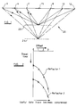
- Figure 1 of the accompanying drawings schematically illustrates an idealised source and receiver arrangement arranged along a line.
- the sources and receivers are arranged about a common mid-point 15.
- the stratum or rock 20 beneath the sources and receivers will be assumed to be isotropic and to contain first and second horizontal partial reflectors 22 and 24, respectively. Seismic energy produced from the actuation of the first source 2 is reflected from the partial reflectors 22 and 24 and received by each of the receivers 8, 10 and 12.
- only energy reflected from beneath the common midpoint 15 will be considered herein.
- the offset axis of Figure 2 is labelled 1, 2, and 3 to refer to the travel time between the first source and first receiver, the second source and second receiver, and the third source and third receiver, respectively.
- the traces are assigned to their respective common midpoints such that the geology beneath the line of sources and receivers can be probed at a plurality of positions.
- a velocity analysis is then performed for each common midpoint, and indeed, for each reflector 22 and 24. This is achieved by specifying a range of hyperbolas, as defined in the above equation, related to a range of velocities and computing the mean reflection amplitude along all specified hyperbolas within that range.
- the seismic traces for a plurality of offsets are then converted, in accordance with the hyperbolas, to equivalent traces having zero offset and the traces are then summed.
- the mean amplitudes at zero offset are then examined to determine which hyperbola gives the best result.
- all the seismic data relating to the common midpoint for which the hyperbola has been determined are then corrected for normal moved and stacked so as to provide a stacked trace for that particular common midpoint.
- the stacked trace has an improved signal to noise ratio compared to the traces recorded at the receivers.
- the accuracy of the seismic data processing could be improved if the actual round trip travel times were used as opposed to those fitted to a hyperbolic curve.
- a method of processing seismic data traces assigned to a common reflection point comprising analysing the seismic data traces to determine similar features therein relating to a reflection of seismic energy from a first reflector, and ordering those features with respect to at least offset so as to identify a travel time surface of the seismic energy reflected from the first reflector
- the traces are summed to form a composite trace having zero offset.
- the seismic array is an array adapted for three dimensional seismic surveying and the traces connected thereby are sorted into an array of cells (or bins) prior to analysis. A more detailed description of the binning process can be found in GB-A-2 247 751.
- the actual round trip travel times with respect to offset may be fitted to a curve so as to define a travel time line.
- the fitting may also be performed with respect to position of the common reflection point (in one or two dimensions) so as to define a travel time surface within a three or more dimensional space.
- the travel time curve or surface has a higher order than a hyperbolic curve or surface.
- a velocity model is used to determine the contribution of the seismic traces to the common reflection point.
- the common reflection point is a common midpoint.
- the method may be repeated for reflections from further reflectors.
- the method may be guided by pre-existing survey data or from estimates of the geology of the region. This may reduce the amount of computation performed on the data since the search for similar features will be guided to approximately the right position in a data space and consequently will make fewer unsuccessful analyses.
- the present invention replaces the prior art stacking velocity analysis step and the hyperbolic stacking step with a travel-time extraction step and a summation step along the extracted time curves or surface.
- the travel-time extraction is performed continuously along acquisition lines.
- the travel-time curves can take any shape and do not have any hyperbolic constraints.
- the summation can then be performed along these general travel-time curves (or surfaces) and the average amplitudes, or any other amplitude approximations, are posted at the position where the travel-time curves intersect the zero-offset axis.
- All of the available seismic data for a common midpoint may be used to develop the actual travel-time curve.
- the traces are examined by a computer to determine parts thereof which relate to the same reflection.
- the computer executes a programme that exploits the continuity of reflection amplitudes in travel-time and offset and optionally displacement (along the seismic line).
- a picked stack of travel-time curves relating to different travel-time depths is used to interpolate travel times to be used for the computations of the mean amplitudes that are posted to the zero offset position.
- the interpolation allows the processing step to account for the fact that the offsets may not be arranged in a regular array (i.e. all the offsets may not be an exact integer multiple of a unit offset).
- the processing does not involve the conventional normal move-out processing and thereby avoids the distortion introduced by such a technique into the traces and, as a consequence, higher frequencies at larger offsets are maintained.
- the interpolation may also be performed in the time domain with sub-sample accuracy. This is of benefit in extracting information from traces with large offsets because it helps to overcome the data compression which occurs with increasing offset.
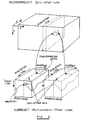
- the seismic measurements can be analysed in a four-dimensional space, as shown in Figure 3.
- the dimensions of this space are x and y spatial coordinates of the acquisition line, an offset coordinate o, and a travel time coordinate t.
- the seismic data can be transformed between the four dimensional zero-offset cube (the masterproject cube) and one or more subproject cubes having non-zero offset.
- the mean amplitude value over all offsets along a pre-specified curve in the subproject cube is posted at a respective position where this cube intersects the zero-offset plane t min and corresponding to the respective x and y spatial position along the acquisition line of the masterproject cube.
- the new cross-section consisting of the mean amplitude values and t min are generated in the master project cube along the x and y coordinates of the acquisition line. More than one subproject cube may be used, as illustrated in Figure 3. This represents a situation where more than one wave mode is measured and is described later below.
- the present invention extracts the exact travel-times explicitly from the data in the offset cube along the acquisition line and then sums along the travel line curves to get the mean amplitude at the zero-offset location. This provides improved quality of the zero-offset results.
- new wavefronts may be interpolated.
- the maximum density of the interpolated wavefronts is determined by the sample rate of the zero-offset cross-section.
- the position of the interpolated wavefront is determined by the neighbouring extracted wavefronts.
- the interpolated wavefronts together with the associated amplitude values are computed for the non-zero offsets. This gives enhanced fidelity of the zero-offset transformation.
- Figure 4 schematically illustrates a series of common midpoint traces arranged in order of decreasing offset.
- a given feature in any trace, such as reflection 30 of trace 80 along the offset axis has a counterpart in the neighbouring traces 79 and 81.
- the computer is arranged to locate a given feature and its counterparts and to extract the "path" of this feature in travel time with respect to changes in offset.
- the computer is arranged to start its analysis from one or more seed points.
- the seed point is a user defined event on a trackable path or surface of events. This does not necessarily imply that the seed points has been manually entered into the computer.
- the or each seed point may be a predetermined event that the computer has been instructed to search for (such as the first seismic signal occurring within a given travel time range for a preselected offset.
- the computer examines data occurring within a "neighbourhood" of the or each seed point to locate a similar seismic signal.
- a neighbourhood is a region of a data space (i.e. x, y coordinates, time travel, offset).
- the similar seismic signal may be identified using such comparison techniques as peak value identification or cross-correlation. Once a neighbouring event has been identified, it is itself used as a seed point for subsequent analysis of the data. By a repetition of the above sequence, the occurrence of a seismic reflection can be tracked through a multidimensional data space.
- the search need not be done without reference to other guiding data. For example, if an earlier seismic analysis of the geology is available or an a priori surface model (velocity distribution as a function of depth) is available, this data may be used to generate travel-time data which could be used as starting points for the analysis of the acquired data or which may be used to guide the subsequent analysis of the data.
- trajectory stacking can be achieved, for example, by ray tracing.
- Such stacking can be carried out for all source and receiver positions about the zero-offset axis.
- the stacking trajectories correspond to a set of parallel straight lines (not shown) over the offset range of the offset cube ( Figure 3), and the common reflection point therefore coincides with the common midpoint.
- the stacking trajectories can also be determined using the velocity model when the source and receiver positions deviate from a common horizontal plane (datum) by defining the source and receiver positions with respect to a corresponding common reflection point.
- the common midpoint does not coincide with the common reflection point, even if the subsurfaces are stratified.
- a velocity model is particularly useful when elastic waves generated by a seismic source are converted to a different mode of wave propagation, for example, the conversion at the reflecting interface of a compression wave (pressure mode) to a shear wave (shear mode).
- a compression wave pressure mode
- shear wave shear mode
- Curve 32 accurately matches the variation in travel time with respect to offset, which is itself a poor approximation to a hyperbolic function.
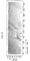
- the extraction of the travel time curves can be repeated along the acquisition line in order to determine a travel time surface, as shown in ' Figure 5.
- the black lines in Figure 5 map out contours within the travel time surface.
Landscapes
- Engineering & Computer Science (AREA)
- Remote Sensing (AREA)
- Physics & Mathematics (AREA)
- Life Sciences & Earth Sciences (AREA)
- Acoustics & Sound (AREA)
- Environmental & Geological Engineering (AREA)
- Geology (AREA)
- General Life Sciences & Earth Sciences (AREA)
- General Physics & Mathematics (AREA)
- Geophysics (AREA)
- Geophysics And Detection Of Objects (AREA)
- Electric Clocks (AREA)
Claims (12)
- Procédé de traitement de traces de données sismiques assignées à un point de réflexion commun, comprenant l'analyse des traces de données sismiques pour déterminer des caractéristiques similaires dans celles-ci ayant rapport à une réflexion d'énergie sismique depuis un premier réflecteur, et la mise en ordre de ces caractéristiques relativement à au moins un déport afin d'identifier une surface de temps de parcours de l'énergie sismique réfléchie depuis le premier réflecteur.
- Procédé selon la revendication 1, dans lequel les traces sont analysées pour déterminer le temps de parcours en fonction de la position du point de réflexion commun pour l'énergie sismique réfléchie depuis le premier réflecteur.
- Procédé selon l'une quelconque des revendications précédentes, dans lequel les traces sismiques sont transformées en une trace équivalente de déport nul et les traces équivalentes de déport nul sont additionnées pour former une trace composite.
- Procédé selon l'une quelconque des revendications précédentes, dans lequel des parties similaires de traces sont identifiées en recherchant des caractéristiques qui varient d'une façon sensiblement continue relativement à des changements de déport ou de position du point de réflexion commun.
- Procédé selon l'une quelconque des revendications précédentes, comprenant en outre l'étape d'ajustement d'une surface de temps de parcours définie mathématiquement en fonction d'au moins le déport par rapport à la surface de temps de parcours pour les caractéristiques similaires des traces identifiées dans l'étape d'analyse.
- Procédé selon l'une quelconque des revendications 1 à 4, comprenant en outre l'étape d'ajustement d'une courbe de temps de parcours définie mathématiquement en fonction du déport par rapport à la surface de temps de parcours pour les caractéristiques similaires des traces définies dans l'étape d'analyse.
- Procédé selon l'une quelconque des revendications précédentes, dans lequel les traces sismiques sont analysées pour déterminer des caractéristiques dans celles-ci ayant rapport à la réflexion depuis au moins un deuxième réflecteur, et pour identifier une surface de temps de parcours pour des réflexions depuis le au moins un deuxième réflecteur.
- Procédé selon l'une quelconque des revendications précédentes, dans lequel les caractéristiques similaires identifiées dans l'étape d'analyse sont additionnées.
- Procédé selon l'une quelconque des revendications précédentes, dans lequel une estimation des propriétés géologiques d'une zone étudiée est utilisée comme une estimation initiale dans une recherche de caractéristiques dans les traces de données ayant rapport à une réflexion sismique.
- Procédé selon la revendication 9, dans lequel l'estimation des propriétés géologiques est utilisée pour guider la recherche de caractéristiques dans les traces de données.
- Procédé selon l'une quelconque des revendications précédentes, dans lequel un modèle de vitesse est utilisé pour déterminer la contribution des traces sismiques au point de réflexion commun.
- Procédé selon l'une quelconque des revendications précédentes, dans lequel le point de réflexion commun est un point-milieu commun.
Applications Claiming Priority (3)
| Application Number | Priority Date | Filing Date | Title |
|---|---|---|---|
| GB9508525 | 1995-04-27 | ||
| GBGB9508525.4A GB9508525D0 (en) | 1995-04-27 | 1995-04-27 | Method of processing seismic data |
| PCT/GB1996/001018 WO1996034301A1 (fr) | 1995-04-27 | 1996-04-29 | Procede de traitement de donnees sismiques pour obtenir la courbe de temps de parcours |
Publications (2)
| Publication Number | Publication Date |
|---|---|
| EP0823060A1 EP0823060A1 (fr) | 1998-02-11 |
| EP0823060B1 true EP0823060B1 (fr) | 2000-06-07 |
Family
ID=10773584
Family Applications (1)
| Application Number | Title | Priority Date | Filing Date |
|---|---|---|---|
| EP96912108A Expired - Lifetime EP0823060B1 (fr) | 1995-04-27 | 1996-04-29 | Procede de traitement de donnees sismiques pour obtenir la courbe de temps de parcours |
Country Status (8)
| Country | Link |
|---|---|
| US (1) | US6049509A (fr) |
| EP (1) | EP0823060B1 (fr) |
| AU (1) | AU705172B2 (fr) |
| CA (1) | CA2218849C (fr) |
| DE (1) | DE69608795T2 (fr) |
| GB (1) | GB9508525D0 (fr) |
| NO (1) | NO318867B1 (fr) |
| WO (1) | WO1996034301A1 (fr) |
Families Citing this family (29)
| Publication number | Priority date | Publication date | Assignee | Title |
|---|---|---|---|---|
| US6138075A (en) * | 1998-08-05 | 2000-10-24 | Landmark Graphics Corporation | Methods and apparatus for analyzing seismic data |
| GB2368911A (en) * | 2000-11-09 | 2002-05-15 | Geco Prakla | Computing a stacked seismic line by interpolation between known stacks |
| GB0100207D0 (en) * | 2001-01-05 | 2001-02-14 | Geco Prakla Uk Ltd | A method of processing seismic data |
| FR2851662B1 (fr) * | 2003-02-24 | 2006-08-25 | Socomate Internat | Procede et dispositif de detection de discontinuites dans un milieu |
| US8234923B2 (en) * | 2004-09-20 | 2012-08-07 | Innervision Medical Technologies Inc. | Systems and methods for ultrasound imaging |
| US7819805B2 (en) | 2004-09-20 | 2010-10-26 | Mgb Investments Limited Partnership | Sub-nyquist sampling of acoustic signals in ultrasound imaging |
| US7850611B2 (en) * | 2004-09-20 | 2010-12-14 | Innervision Medical Technologies Inc. | System and methods for improved ultrasound imaging |
| WO2007092054A2 (fr) | 2006-02-06 | 2007-08-16 | Specht Donald F | procEDE et appareil permettant de visualiser les artEres coronaires A l'aide d'ultrasons |
| EP2088932B1 (fr) | 2006-10-25 | 2020-04-08 | Maui Imaging, Inc. | Procédé et appareil de production d'images ultrasonores au moyen d'une pluralité d'orifices |
| US9788813B2 (en) | 2010-10-13 | 2017-10-17 | Maui Imaging, Inc. | Multiple aperture probe internal apparatus and cable assemblies |
| US9339256B2 (en) | 2007-10-01 | 2016-05-17 | Maui Imaging, Inc. | Determining material stiffness using multiple aperture ultrasound |
| US9282945B2 (en) | 2009-04-14 | 2016-03-15 | Maui Imaging, Inc. | Calibration of ultrasound probes |
| US9247926B2 (en) | 2010-04-14 | 2016-02-02 | Maui Imaging, Inc. | Concave ultrasound transducers and 3D arrays |
| US7969818B2 (en) * | 2007-12-19 | 2011-06-28 | Pgs Geophysical As | Method for regularizing offset distribution in towed seismic streamer data |
| JP5485373B2 (ja) | 2009-04-14 | 2014-05-07 | マウイ イマギング,インコーポレーテッド | 複数開口の超音波アレイ位置合せ装置 |
| KR102322776B1 (ko) | 2010-02-18 | 2021-11-04 | 마우이 이미징, 인코포레이티드 | 초음파 이미지를 구성하는 방법 및 이를 위한 다중-개구 초음파 이미징 시스템 |
| JP6407719B2 (ja) | 2011-12-01 | 2018-10-17 | マウイ イマギング,インコーポレーテッド | ピングベース及び多数開口ドップラー超音波を用いた運動の検出 |
| JP2015503404A (ja) | 2011-12-29 | 2015-02-02 | マウイ イマギング,インコーポレーテッド | 任意経路のmモード超音波イメージング |
| EP2833791B1 (fr) | 2012-03-26 | 2022-12-21 | Maui Imaging, Inc. | Procédés pour l'amélioration de la qualité d'images ultrasonores par l'application de facteurs de pondération |
| CN104620128B (zh) | 2012-08-10 | 2017-06-23 | 毛伊图像公司 | 多孔径超声探头的校准 |
| US9986969B2 (en) | 2012-09-06 | 2018-06-05 | Maui Imaging, Inc. | Ultrasound imaging system memory architecture |
| CN103676827A (zh) | 2012-09-06 | 2014-03-26 | Ip音乐集团有限公司 | 用于远程控制音频设备的系统和方法 |
| WO2014160291A1 (fr) | 2013-03-13 | 2014-10-02 | Maui Imaging, Inc. | Alignement de groupements de transducteurs à ultrasons et ensemble de sonde à ouvertures multiples |
| US9883848B2 (en) | 2013-09-13 | 2018-02-06 | Maui Imaging, Inc. | Ultrasound imaging using apparent point-source transmit transducer |
| US10401493B2 (en) | 2014-08-18 | 2019-09-03 | Maui Imaging, Inc. | Network-based ultrasound imaging system |
| CN107613878B (zh) | 2015-03-30 | 2021-04-06 | 毛伊图像公司 | 用于检测物体运动的超声成像系统和方法 |
| EP4697068A3 (fr) | 2016-01-27 | 2026-04-22 | Maui Imaging, Inc. | Imagerie ultrasonore à sondes à matrice creuse |
| JP7724853B2 (ja) | 2020-10-21 | 2025-08-18 | マウイ イマギング,インコーポレーテッド | 多数開口超音波を用いた組織の特徴付けのためのシステム及び方法 |
| EP4236811A4 (fr) | 2020-11-02 | 2024-10-09 | Maui Imaging, Inc. | Systèmes et procédés d'amélioration de la qualité d'image ultrasonore |
Family Cites Families (10)
| Publication number | Priority date | Publication date | Assignee | Title |
|---|---|---|---|---|
| US3417370A (en) * | 1966-12-23 | 1968-12-17 | Texas Instruments Inc | Seismic velocity correlation |
| US3651451A (en) * | 1969-10-23 | 1972-03-21 | Mobil Oil Corp | Continuous velocity estimation |
| US3696331A (en) * | 1970-07-22 | 1972-10-03 | Mobil Oil Corp | Automated process for determining subsurface velocities from seismograms |
| US4503527A (en) * | 1981-03-30 | 1985-03-05 | Mobil Oil Corporation | Method for enhancement of the signal-to-noise ratio in seismic reflection signals |
| NO854447L (no) * | 1984-11-08 | 1986-05-09 | Texas Instruments Inc | Fremgangsmaate og innretning for automatisk frembringelse av representasjoner av tredimensjonale horisonter ut fra behandlede, seismiske data. |
| US4849887A (en) * | 1987-08-28 | 1989-07-18 | Amoco Corporation | Horizon velocity analysis |
| US5050131A (en) * | 1991-01-17 | 1991-09-17 | Conoco Inc. | Quantitative method for evaluating velocity model quality |
| US5153858A (en) * | 1991-07-09 | 1992-10-06 | Landmark Graphics Corporation | Method for finding horizons in 3D seismic data |
| US5414674A (en) * | 1993-11-12 | 1995-05-09 | Discovery Bay Company | Resonant energy analysis method and apparatus for seismic data |
| US5563949A (en) * | 1994-12-12 | 1996-10-08 | Amoco Corporation | Method of seismic signal processing and exploration |
-
1995
- 1995-04-27 GB GBGB9508525.4A patent/GB9508525D0/en active Pending
-
1996
- 1996-04-29 WO PCT/GB1996/001018 patent/WO1996034301A1/fr not_active Ceased
- 1996-04-29 DE DE69608795T patent/DE69608795T2/de not_active Expired - Fee Related
- 1996-04-29 AU AU55060/96A patent/AU705172B2/en not_active Ceased
- 1996-04-29 CA CA002218849A patent/CA2218849C/fr not_active Expired - Fee Related
- 1996-04-29 EP EP96912108A patent/EP0823060B1/fr not_active Expired - Lifetime
- 1996-04-29 US US08/945,075 patent/US6049509A/en not_active Expired - Lifetime
-
1997
- 1997-10-27 NO NO19974970A patent/NO318867B1/no not_active IP Right Cessation
Also Published As
| Publication number | Publication date |
|---|---|
| CA2218849C (fr) | 2000-10-24 |
| NO974970D0 (no) | 1997-10-27 |
| WO1996034301A1 (fr) | 1996-10-31 |
| DE69608795T2 (de) | 2000-12-28 |
| US6049509A (en) | 2000-04-11 |
| DE69608795D1 (de) | 2000-07-13 |
| GB9508525D0 (en) | 1995-06-14 |
| NO318867B1 (no) | 2005-05-18 |
| NO974970L (no) | 1997-12-22 |
| AU705172B2 (en) | 1999-05-20 |
| AU5506096A (en) | 1996-11-18 |
| CA2218849A1 (fr) | 1996-10-31 |
| EP0823060A1 (fr) | 1998-02-11 |
Similar Documents
| Publication | Publication Date | Title |
|---|---|---|
| EP0823060B1 (fr) | Procede de traitement de donnees sismiques pour obtenir la courbe de temps de parcours | |
| US7355923B2 (en) | Seismic analysis using post-imaging seismic anisotropy corrections | |
| EP0548384B1 (fr) | Méthode pour l'amélioration de la résolution sismique de structures géologiques | |
| US6055482A (en) | Method of seismic signal processing | |
| US7069150B2 (en) | Method for optimizing migration fields using time slice analysis | |
| US20110166790A1 (en) | Seismic Processing for the Elimination of Multiple Reflections | |
| US20040015296A1 (en) | Seismic processing with general non-hyperbolic travel-time corrections | |
| US7110323B2 (en) | Method, system and apparatus for interpreting seismic data using duplex waves | |
| EP2548052B1 (fr) | Système et procédé d'imagerie vsp de flancs de sel 3d avec des ondes transmises | |
| EP2185947A2 (fr) | Analyse complexe de cinématiques pour corrections non hyperboliques d'obliquité | |
| US20240219597A1 (en) | Sparse ocean bottom nodes and mini-streamer acquisition system for enhancing subsurface imaging | |
| WO2001029581A1 (fr) | Procede pour obtenir des fonctions de transfert lors du traitement et de l'exploration de signaux sismiques | |
| CA2606201C (fr) | Procede de traitement de donnees sismiques pour caracterisation avo ou avoa | |
| AU2006237350B2 (en) | Seismic data processing method for RMO picking | |
| Palmer | Integrating long and short wavelength time and amplitude statics | |
| GB2368911A (en) | Computing a stacked seismic line by interpolation between known stacks | |
| Talagapu | 2d and 3d land seismic data acquisition and seismic data processing | |
| Talwani et al. | Some recent developments in the acquisition and processing of seismic data | |
| Hassani et al. | Imaging crustal structures through a passive seismic imaging approach in a mining area in Saxony, Germany | |
| Sánchez et al. | 3D beamforming for surface wave dispersion analysis and inversion in complex land seismic data | |
| Mahdavi et al. | Multi-channel analysis of surface waves using Common Midpoint Cross Correlation method | |
| Druzhinin | Wavefield Separation, Multiple Attenuation and Migration in Terms of Local Beam Attributes | |
| Talwani et al. | Imaging of convergent zones by seismic acquisition and processing | |
| Benz et al. | The Norilsk DSS Profile in Northern Siberia: Interpretation of the Velocity Structure and Coinparison with Basin and Range and New England Profiling Results | |
| WO1998020368A1 (fr) | Alignement de traces sismiques |
Legal Events
| Date | Code | Title | Description |
|---|---|---|---|
| PUAI | Public reference made under article 153(3) epc to a published international application that has entered the european phase |
Free format text: ORIGINAL CODE: 0009012 |
|
| 17P | Request for examination filed |
Effective date: 19971117 |
|
| AK | Designated contracting states |
Kind code of ref document: A1 Designated state(s): DE FR IT NL |
|
| GRAG | Despatch of communication of intention to grant |
Free format text: ORIGINAL CODE: EPIDOS AGRA |
|
| 17Q | First examination report despatched |
Effective date: 19990827 |
|
| GRAG | Despatch of communication of intention to grant |
Free format text: ORIGINAL CODE: EPIDOS AGRA |
|
| GRAH | Despatch of communication of intention to grant a patent |
Free format text: ORIGINAL CODE: EPIDOS IGRA |
|
| GRAH | Despatch of communication of intention to grant a patent |
Free format text: ORIGINAL CODE: EPIDOS IGRA |
|
| GRAA | (expected) grant |
Free format text: ORIGINAL CODE: 0009210 |
|
| ITF | It: translation for a ep patent filed | ||
| AK | Designated contracting states |
Kind code of ref document: B1 Designated state(s): DE FR IT NL |
|
| REF | Corresponds to: |
Ref document number: 69608795 Country of ref document: DE Date of ref document: 20000713 |
|
| ET | Fr: translation filed | ||
| PLBE | No opposition filed within time limit |
Free format text: ORIGINAL CODE: 0009261 |
|
| STAA | Information on the status of an ep patent application or granted ep patent |
Free format text: STATUS: NO OPPOSITION FILED WITHIN TIME LIMIT |
|
| 26N | No opposition filed | ||
| PGFP | Annual fee paid to national office [announced via postgrant information from national office to epo] |
Ref country code: FR Payment date: 20030408 Year of fee payment: 8 |
|
| PGFP | Annual fee paid to national office [announced via postgrant information from national office to epo] |
Ref country code: DE Payment date: 20030508 Year of fee payment: 8 |
|
| PG25 | Lapsed in a contracting state [announced via postgrant information from national office to epo] |
Ref country code: DE Free format text: LAPSE BECAUSE OF NON-PAYMENT OF DUE FEES Effective date: 20041103 |
|
| PG25 | Lapsed in a contracting state [announced via postgrant information from national office to epo] |
Ref country code: FR Free format text: LAPSE BECAUSE OF NON-PAYMENT OF DUE FEES Effective date: 20041231 |
|
| REG | Reference to a national code |
Ref country code: FR Ref legal event code: ST |
|
| PGFP | Annual fee paid to national office [announced via postgrant information from national office to epo] |
Ref country code: IT Payment date: 20070525 Year of fee payment: 12 |
|
| PGFP | Annual fee paid to national office [announced via postgrant information from national office to epo] |
Ref country code: NL Payment date: 20080403 Year of fee payment: 13 |
|
| PG25 | Lapsed in a contracting state [announced via postgrant information from national office to epo] |
Ref country code: IT Free format text: LAPSE BECAUSE OF NON-PAYMENT OF DUE FEES Effective date: 20080429 |
|
| NLV4 | Nl: lapsed or anulled due to non-payment of the annual fee |
Effective date: 20091101 |
|
| PG25 | Lapsed in a contracting state [announced via postgrant information from national office to epo] |
Ref country code: NL Free format text: LAPSE BECAUSE OF NON-PAYMENT OF DUE FEES Effective date: 20091101 |