EP0823267A2 - Appareil de sport avec affichage des données pour un utilisateur - Google Patents
Appareil de sport avec affichage des données pour un utilisateur Download PDFInfo
- Publication number
- EP0823267A2 EP0823267A2 EP97113217A EP97113217A EP0823267A2 EP 0823267 A2 EP0823267 A2 EP 0823267A2 EP 97113217 A EP97113217 A EP 97113217A EP 97113217 A EP97113217 A EP 97113217A EP 0823267 A2 EP0823267 A2 EP 0823267A2
- Authority
- EP
- European Patent Office
- Prior art keywords
- wheel
- voltage
- evaluation
- path
- display device
- Prior art date
- Legal status (The legal status is an assumption and is not a legal conclusion. Google has not performed a legal analysis and makes no representation as to the accuracy of the status listed.)
- Granted
Links
- 238000011156 evaluation Methods 0.000 claims abstract description 26
- 230000032258 transport Effects 0.000 claims 1
- 239000003990 capacitor Substances 0.000 description 11
- 238000013461 design Methods 0.000 description 6
- 230000000694 effects Effects 0.000 description 6
- 230000006870 function Effects 0.000 description 6
- 238000000034 method Methods 0.000 description 6
- 230000033001 locomotion Effects 0.000 description 4
- 238000006073 displacement reaction Methods 0.000 description 3
- 230000005415 magnetization Effects 0.000 description 3
- 230000003287 optical effect Effects 0.000 description 3
- 239000000243 solution Substances 0.000 description 3
- BGPVFRJUHWVFKM-UHFFFAOYSA-N N1=C2C=CC=CC2=[N+]([O-])C1(CC1)CCC21N=C1C=CC=CC1=[N+]2[O-] Chemical compound N1=C2C=CC=CC2=[N+]([O-])C1(CC1)CCC21N=C1C=CC=CC1=[N+]2[O-] BGPVFRJUHWVFKM-UHFFFAOYSA-N 0.000 description 2
- 230000000875 corresponding effect Effects 0.000 description 2
- 238000001514 detection method Methods 0.000 description 2
- 238000011161 development Methods 0.000 description 2
- 230000018109 developmental process Effects 0.000 description 2
- 238000005516 engineering process Methods 0.000 description 2
- 230000001939 inductive effect Effects 0.000 description 2
- 238000005259 measurement Methods 0.000 description 2
- 238000005096 rolling process Methods 0.000 description 2
- 238000012549 training Methods 0.000 description 2
- 230000005540 biological transmission Effects 0.000 description 1
- 230000037396 body weight Effects 0.000 description 1
- 238000005266 casting Methods 0.000 description 1
- 238000010276 construction Methods 0.000 description 1
- 230000002596 correlated effect Effects 0.000 description 1
- 230000001419 dependent effect Effects 0.000 description 1
- 238000010586 diagram Methods 0.000 description 1
- 238000004512 die casting Methods 0.000 description 1
- 238000001746 injection moulding Methods 0.000 description 1
- 238000004519 manufacturing process Methods 0.000 description 1
- 238000002360 preparation method Methods 0.000 description 1
- 238000003825 pressing Methods 0.000 description 1
- 238000012545 processing Methods 0.000 description 1
- 230000035945 sensitivity Effects 0.000 description 1
- 238000009987 spinning Methods 0.000 description 1
- 239000013589 supplement Substances 0.000 description 1
- 230000002123 temporal effect Effects 0.000 description 1
- 238000004804 winding Methods 0.000 description 1
- 210000000707 wrist Anatomy 0.000 description 1
Images
Classifications
-
- A—HUMAN NECESSITIES
- A63—SPORTS; GAMES; AMUSEMENTS
- A63C—SKATES; SKIS; ROLLER SKATES; DESIGN OR LAYOUT OF COURTS, RINKS OR THE LIKE
- A63C17/00—Roller skates; Skate-boards
- A63C17/22—Wheels for roller skates
-
- A—HUMAN NECESSITIES
- A63—SPORTS; GAMES; AMUSEMENTS
- A63C—SKATES; SKIS; ROLLER SKATES; DESIGN OR LAYOUT OF COURTS, RINKS OR THE LIKE
- A63C17/00—Roller skates; Skate-boards
- A63C17/26—Roller skates; Skate-boards with special auxiliary arrangements, e.g. illuminating, marking, or push-off devices
-
- G—PHYSICS
- G01—MEASURING; TESTING
- G01P—MEASURING LINEAR OR ANGULAR SPEED, ACCELERATION, DECELERATION, OR SHOCK; INDICATING PRESENCE, ABSENCE, OR DIRECTION, OF MOVEMENT
- G01P3/00—Measuring linear or angular speed; Measuring differences of linear or angular speeds
- G01P3/42—Devices characterised by the use of electric or magnetic means
- G01P3/44—Devices characterised by the use of electric or magnetic means for measuring angular speed
- G01P3/48—Devices characterised by the use of electric or magnetic means for measuring angular speed by measuring frequency of generated current or voltage
- G01P3/481—Devices characterised by the use of electric or magnetic means for measuring angular speed by measuring frequency of generated current or voltage of pulse signals
- G01P3/487—Devices characterised by the use of electric or magnetic means for measuring angular speed by measuring frequency of generated current or voltage of pulse signals delivered by rotating magnets
-
- G—PHYSICS
- G01—MEASURING; TESTING
- G01P—MEASURING LINEAR OR ANGULAR SPEED, ACCELERATION, DECELERATION, OR SHOCK; INDICATING PRESENCE, ABSENCE, OR DIRECTION, OF MOVEMENT
- G01P3/00—Measuring linear or angular speed; Measuring differences of linear or angular speeds
- G01P3/42—Devices characterised by the use of electric or magnetic means
- G01P3/50—Devices characterised by the use of electric or magnetic means for measuring linear speed
-
- A—HUMAN NECESSITIES
- A63—SPORTS; GAMES; AMUSEMENTS
- A63C—SKATES; SKIS; ROLLER SKATES; DESIGN OR LAYOUT OF COURTS, RINKS OR THE LIKE
- A63C2203/00—Special features of skates, skis, roller-skates, snowboards and courts
- A63C2203/18—Measuring a physical parameter, e.g. speed, distance
Definitions
- the invention relates to a sports device according to the preamble of claim 1.
- Sports equipment serves their users on the one hand for leisure activities, but on the other hand also exercise, endurance and strength training.
- data displays which provide the user with information about the activity of the Give user.
- An example of such data displays are, for example, speedometers with Mileage on bicycles, the user of the bike the distance traveled and display the current speed.
- sports equipment Display devices common. Solutions are also known in which body functions such as about pulse rate are displayed.
- inline skates have been used as sports equipment and for Leisure use found widespread use. They can also be used especially for movement and Endurance training can be used. Additional equipment is also available for inline skates known. For example, in US Pat. No. 5,484,164 there is an optical warning device with which the users of such inline skates can draw attention to themselves.
- the invention has for its object such sports equipment used for locomotion to equip with wheels, rollers and the like with a device for data display.
- the sports equipment according to the invention is equipped with a device that the Locomotion characterizing key figures determined and displayed.
- the sports device has a voltage generator integrated in a wheel, from the kinetic energy when the sports equipment is used as intended is able to generate electrical voltage, also an integrated in the wheel Sensor for the detection of path impulses and next to it also arranged in the wheel Transmitter that transmits the detected path pulses wirelessly to a receiver Evaluates and displays.
- a voltage generator integrated in a wheel, from the kinetic energy when the sports equipment is used as intended is able to generate electrical voltage
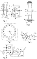
- Fig. 1 means a wheel of an inline skate that is rotatable about an axis 2, which in a not shown drive of an inline skate is attached.
- the smooth-running Rotatability of the wheel 1 is achieved by a ball bearing 3 arranged on both sides, the on the one hand with its inner ring on axis 2 and on the other hand with its outer ring the wheel 1 is connected.
- a stator 4, on which magnets 5 are connected, is firmly connected to axis 2 are attached.
- the stator 4 advantageously has a circular shape and the magnets 5 are arranged along its outer diameter.
- a coil 6 is fixedly arranged in the wheel 1, so that the coil 6 when the wheel 1 rotates about the axis 2 on a circular path around the Stator 4 with the magnets 5 moves ⁇
- This coil 6 thus forms together with those on the Stator 4 arranged magnets 5 a voltage generator 7, the components of which in the Figure are summarized with a dashed line.
- the Control circuit 9 is - not shown in the drawing for clarity - with the Coil 6 connected.
- One of the tasks of the control circuit 9 is the preparation of the in the Coil 6 generated electrical energy for the operation of the transmitter 10.
- the transmitter 10 has an antenna 12 connected.
- the transmitter 10 transmits a signal modulated with displacement pulses via the antenna 12.
- This Signal can be received by an antenna 20 of an evaluation and display device 21 will.
- the antenna 20 is connected to a receiver 22 so that the received signal can be detected by the receiver 22.
- the receiver 22 demodulates the received one Signal, thus recovers the path pulse signal and makes it available at an output.
- This output of the receiver 22 is connected to an input of a signal converter 23 connected.
- the path pulse signal is converted into one for one Microprocessor 24 brought appropriate form and in this form over a corresponding Connection passed to the microprocessor 24.
- the microprocessor 24 processes the incoming path pulse signals, calculated from the time sequence of the individual path pulses the data of interest to the user and controls a display 25 so that the data thereon being represented.
- An operating device 26 is also advantageously provided, with the help of which the microprocessor 24 can be influenced in such a way that it is determined by the user in each case displays the desired information.
- the evaluation and display device 21, the Receiver 22, the signal converter 23, the microprocessor 24, the display 25 and the Operating device 26 is supplied with voltage by a battery 27.
- the device described above works as follows. If the inline skate on an underground is moved by turning the wheel 1 about the axis 2 in the Coil 6 generates a voltage with which the transmitter 10 is operated.
- the ones from Voltage generator 7 generated voltage is an AC voltage whose frequency is directly related to the movement of the inline skate. According to the Electrical energy generated by the voltage generator 7 using the control circuit 9 in transformed a DC voltage for operating the transmitter 10.
- One also in bike 1 Arranged generator for the generation of path pulses can be of any type be. It is particularly advantageous for the AC voltage generated by the voltage generator 7 can also be used to generate the path impulses.
- Evaluation and Display device 21 with the receiver 22, transmitter 10 and the antennas 12 and 24 are each designed for the relevant frequency. That radiated by the antenna 12 in the wheel 1 Signal, shown in Fig. 1 by a dashed lightning arrow, is from the Antenna 20 recorded in the evaluation and display device 21.
- Path impulses recovered and sent to the microprocessor 24. This processes the incoming path impulses.
- Each path impulse corresponds to a certain distance, which with the Diameter or the circumference of the wheel 1 correlated. For example, if Diameter of the wheel 1 72 mm, the circumference of the wheel 1 has a value of 226.2 mm. If the control circuit 9 emits a travel pulse per revolution of the wheel 1, everyone has Wegimpuls a value of 226.2 mm. By counting the number of path impulses you can the distance covered can be calculated. In an embodiment described later of the voltage generator 7 with 16 magnets, this supplies an alternating voltage, the Frequency corresponds to eight times the number of revolutions.
- each individual path pulse has a value of 28.3 mm.
- the microprocessor 24 can calculate the speed at intervals of two path pulses.
- the diameter of the wheel 1 can be entered.
- inline Skates result in other dimensions.
- the Wear that occurs on wheel 1 over time during use Of the From time to time the user can measure the diameter of the wheel 1 and - should it be from the previous stored value deviate - re-enter using the operating device 26 or change.
- the wheel 1 consists of two wheel disks 30 and a wheel tire 31 surrounding and connecting them, which in turn consists of a carrier 32 and a running body 33 is composed.
- the carrier has 32 shaped pieces 34, engage in the recesses 35 of the barrel body.
- the fittings 34 and the recesses 35 are spatially designed so that they slip the barrel 33 on the carrier 32nd prevent, both in the circumferential direction and in the lateral direction.
- the Shaped pieces 34 are molded directly onto carrier 32.
- the carrier 32 can thus for example, be a suitably designed casting, pressing, injection molding or die casting.
- the Recesses of the barrel 33 are inevitable when the manufacture of the Tire 31 is done in such a way that the carrier 32 in a corresponding Tool is overmolded. This creates an intimate connection between carrier 32 and Running body 33 reached.
- each wheel disc 30 In a suitable central depression of each wheel disc 30, one is already connected fitted with the ball bearing 3 mentioned.
- the inner ring of the ball bearing 3 is with the Axis 2 connected.
- the wheel disks 30 are firmly connected to the wheel tire 31, wherein in Analogous to the aforementioned design of the wheel tire 31, the interlocking surfaces of Wheel disks 30 and wheel tires 31 are designed so that both the slipping of the Wheel tire 31 in the circumferential direction and the twisting of the two wheel disks 30 against each other is impossible. This can be done, for example, with appropriate grooves, notches and such things happen.
- the voltage generator 7 is shown schematically. It consists of the coil 6 and a number of magnets 5.
- the magnets 5 are along the circumferential line of the stator 4 arranged.
- the stator 4 is rigidly connected to the axis 2. Since axis 2 is not Drive shown is rigidly attached, so the stator 4 is rigid in the drive, rotates not with the wheel 1 rotating. In contrast, the coil 6 with the connected rotating wheel 1.
- the coil 6 is the circumferential line of the stator 4 directly adjacent.
- the number of magnets 5, which are uniform over the circumference of the stator 4 distributed, is an even number and adjacent magnets 5 are magnetized in opposite directions. When the wheel 1 rotates, an electrical voltage is thus induced in the coil 6.
- the coil 6 is arranged directly outside the circumferential line of the stator 4. Of the remaining air gap should be as small as possible. To as large an amount as possible To be able to gain energy, it can be advantageous to provide several coils 6. So can the number of coils 6 should be half the number of magnets 5. In such a case the coils 6 as the magnets 5 evenly distributed over the circumference, so that the distance from Coil 6 to coil 6 in radians is twice the distance from magnet 5 to Magnet 5 in radians. In the aforementioned case, the individual coils are advantageous all connected in parallel. This solution has the advantage that the yield of electrical Energy is greater than the presence of only one coil 6.
- the number of coils 6 can also be the same as the number of magnets 5. Die Distances in radians are then all the same. In such a case, it is advantageous to form groups of two from adjacent coils 6 and the two coils 6 to be connected antiparallel or with different winding directions in series. All these Groups of two are then connected in parallel.
- the number of magnets 5 is, for example, 16.
- the number of magnets 5 is 8 magnetic north pole N on the front of the stator 4 and the magnetic south pole S. the back.
- the front and back refer to the view according to FIG. 3 the other 8 magnets 5 it is the other way round. Others are within the scope of the invention Magnetization directions and coil arrangements possible.
- a diode 40 is connected to a first connection point of the voltage generator 7, the anode of the diode 40 facing the voltage generator 7.
- a charging capacitor 41, a zener diode 42 and an integrated component 43 are connected to the cathode connection of the diode 40, which forms the positive operating voltage connection + U B.
- the second connection of the charging capacitor 41 and the zener diode 42 are connected to a second connection point of the voltage generator 7. This second connection point forms the reference ground GND, to which the integrated module 43 is also connected.
- the integrated component 43 is, for example, a UHF transmitter of the HX 1000 type from RF Monolithics Inc., Dallas, Texas, USA, implemented in hybrid technology.
- the connection designations "1" to "4" refer to this component, however any other UHF receiver or receiver for long waves can be used. Depending on the information provided by the respective manufacturer, the circuit structure would then have to be varied accordingly.
- the antenna 12 is connected to an input "4" of the integrated module 43 via an adapter 44, for example an inductive or an ohmic resistor.
- the integrated component 43 is connected to the reference ground GND with its connection “3”.
- the integrated module 43 is connected to the positive operating voltage connection + U B with its connection "2".
- a further diode 45 is connected with its anode. Its cathode is connected to an input of a Schmitt trigger 46, the output of which is connected to the connection "1" of the integrated module 43.
- the diode 45 and the Schmitt trigger 46 form that part of the control circuit 9 which, in the manner already described as particularly advantageous, generates the path pulses directly from the AC voltage.
- a further capacitor 47 can be connected between this connection and the reference ground GND, which can dampen any interference signals.
- a further capacitor 48 can be connected between the connection "2" of the integrated component 43 and the reference ground GND, which serves to limit or largely limit the noise of the supply voltage + U B , ie a ripple of the supply voltage + U B to prevent.
- Voltage generator 7 generated AC voltage is one-way by means of the diode 40 rectified and the voltage stored on the charging capacitor 41.
- Zener diode 42 limits the voltage to, for example, 3.6 volts.
- a not shown Limiting resistance for the charging current of the capacitor is then not necessary at all, if the internal resistance of the voltage generator 7, determined by the impedance of the coil 6 shown, is sufficiently large. This is just a design question.
- the ones from Voltage generator 7 generated AC voltage is also via the diode 45, the one Small signal diode is fed to the input of the Schmitt trigger 46.
- the Schmitt trigger 46 forms a sequence of rectangular pulses from the sinusoidal AC voltage, the The frequency of this rectangular pulse train is identical to the frequency of the AC voltage.
- the rectangular pulse train arrives at connection "1" of the integrated module 43.
- the transmitter is modulated with the said rectangular pulse train.
- the dimensioning of the antenna 12 is based on the information provided by the manufacturer of the integrated Building block 43. For example, a short-wire antenna with a length of 60 mm has proven suitable proven. Such an antenna 12 can easily be accommodated in the wheel 1.
- the transmitter 10 mentioned in FIG. 1 is therefore in accordance with the exemplary embodiment according to FIG. 4 realized by the integrated module 43 together with the adapter 44.
- This The functional design of the transmitter 10 is shown in FIG. 4 by a dashed line summarized.
- the transmitter 10 is always in operation when the Voltage generator 7 generated voltage exceeds a certain limit.
- the Circuit is designed so that at a certain minimum rotational speed of the Wheel 1 is the case in inline skate, i.e. at a certain rolling speed of the inline Skates on the road. If the speed is less than this limit, then the speed is Transmitter 10 not in operation. This is expediently indicated in the display 25 by a special symbol "pause" is displayed when the receiver 22 of the evaluation and Display device 21 (FIG. 1) receives no signal.
- Fig. 5 shows a detail of a receiver with an evaluation device that is part of the evaluation and Display device 21 (Fig. 1).
- the antenna 20 is direct or via an adapter, for example an inductive or ohmic resistor with an integrated module 50 connected.
- This integrated module 50 is, for example, a hybrid technology RX 1000 UHF receiver from RF Monolithics Inc., Dallas, Texas, USA.
- the 5 connection designations refer to this component, however any other UHF receiver can be used. Depending on the information provided by the respective manufacturer the circuit structure would then have to be varied accordingly.
- the positive operating voltage connection + U B is connected to the connection "1" and is fed by a battery 27 according to FIG. 1.
- the integrated module 50 has with the connection “8” a ground connection which is connected to the reference ground GND, which is also connected to the battery 27 (FIG. 1).
- the connections "2" and “3” are connected to a capacitor 51, while a further capacitor 52 is connected to the connection "6", the second connection of which is connected to the reference ground GND.
- This information refers to the previously specified module and should be varied accordingly if another type is to be used.
- connection “7" of the integrated module 50 is connected to an input of a microcomputer 53, which is also connected to the positive operating voltage connection + U B and to the reference ground GND.
- a further capacitor 54 is also connected, which serves to suppress interference.
- the microcomputer 53 is, for example, a customer-specific component, also as an ASIC referred to, the a microprocessor, a data memory and for example also elements contains, which functionally correspond to the signal converter 23 (FIG. 1).
- the integrated module 50 with its additional elements such as capacitors 51 and 52 the Receiver 22 of FIG. 1, while the microcomputer 53 the functionality of Microprocessor 24 and the signal converter 23 (Fig. 1) comprises.
- the function of the circuit shown in FIG. 5 is as follows:
- the antenna 20 received signal originating from transmitter 10 (FIGS. 1 and 4) is received by receiver 22 demodulated, i.e. that the sequence of path impulses is recovered.
- These path impulses are processed by the microcomputer 53.
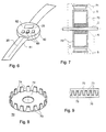
- FIG. 6 shows a spatial shape of a receiver with an evaluation and display device.
- a housing 60 comprises all elements of the evaluation and display device 21 (FIG. 1) housed with the exception of the antenna 20.
- the latter is integrated in a bracelet 61, with which the housing 60 can be attached to the arm of a user.
- a Velcro can be used.
- keys 63 are arranged which form the operating device 26 (FIG. 1).
- Such a spatial form is not mandatory, because there are many alternatives within the scope of the invention Design options. So it is also conceivable, for example, all elements of the evaluation and Integrate display device "1 (Fig. 1) in sunglasses.
- the frame of the Sunglasses can, for example, the antenna 20, the receiver 22, the Signal converter 23, the microprocessor 24 and the control device 26 included while the display 26 is realized, for example, by being integrated into an eyeglass lens with the help of an optical device such as Fresnel lens, the display despite the small Distance to the eye is easily recognizable for the user.
- an optical device such as Fresnel lens
- control circuit 9 (FIG. 4) is, for example, in modified in such a way that the diode 45 in conjunction with the Schmitt trigger 46 generated path pulses by a downstream switching element then not to connection "1" of the integrated block 43 when the pressure sensor arrives at the bottom Lifted wheel 1 signals. This prevents that during the lifting of the Rades 1 from the ground, if necessary, any path impulses still generated.
- the speed can be calculated directly from the time interval between two pulses, on the other hand, the number of path pulses can be determined during a predetermined period of time and the speed can be calculated from it. Both procedures are largely equivalent.
- the process is suitable for low speeds. Accordingly, it can in the microprocessor 24 program also be designed so that it depends on the number of Path impulses per unit of time different methods for determining the speed executes.
- the following values are prepared for display on display 25: current Speed, average speed, maximum speed, travel time since one freely selectable point in time, distance traveled since the freely selectable point in time, total Travel time and / or total distance traveled. It can also be provided the path and speed information in different measurement systems, for example Kilometers or miles, kilometers per hour or miles per hour. Advantageous it can be optionally to additionally display the date and time so that the evaluation and 6 as a wristwatch instead of one Wrist watch can be worn. Realized with the help of the keys 63 (Fig. 6) Operating device 26 (FIG. 1) can be selected and changed in accordance with the display modes.
- Magnets 5 evenly distributed, as in the previously described embodiment Magnetization direction of the magnets 5 changes.
- Half of all magnets 5 are like this magnetizes that the magnetic north pole faces axis 2, while at the other half of the magnets 5, the magnetic south pole of the axis 2 faces.
- Each Adjacent magnets 5 have opposite magnetization directions.
- each cushion 70 has a base area 72 and a number of poles 73 arranged at right angles thereto.
- the number of poles 73 of a cushion 70 can for example 16, 12, 8 or 6.
- the poles 73 have, for example, trapezoidal shapes Shape, so that the cushion 70 has an overall shape like a crown gear, which from the Fig. 7 clearly shows.
- the one cushion 70 compared to the other cushion 70 ⁇ m Is turned 180 ° so that the two pole stars 70 are opposite each other so that their poles 73rd are facing each other.
- the upholstery 70 are advantageously twisted against each other so that each pole 73 engages in a gap 74 of the opposite cushion 70. This is over 9 easily recognizable, in which a development of the lateral surface of the two Upholstery 70 formed cage is shown. Between the poles 73 of the two cushion stars 70 this arrangement of the two upholstery 70 creates an air gap 75, the one Has a meandering shape.
- the constructed according to this advantageous embodiment Voltage generator 7 is characterized in that it is a relative even at low speed emits large electrical power so that there is always enough electrical energy to operate the device according to the invention is available.
- Such an embodiment of the voltage generator 7 can store as much electrical energy generate that in addition to the previously described facility for generating Travel impulses and their wireless transmission by means of the transmitter 10 also another optical and / or acoustic warning device can be operated.
Landscapes
- Physics & Mathematics (AREA)
- General Physics & Mathematics (AREA)
- Devices For Indicating Variable Information By Combining Individual Elements (AREA)
- Arrangements For Transmission Of Measured Signals (AREA)
- Measurement Of Distances Traversed On The Ground (AREA)
- Control Of Indicators Other Than Cathode Ray Tubes (AREA)
Applications Claiming Priority (3)
| Application Number | Priority Date | Filing Date | Title |
|---|---|---|---|
| CH192496 | 1996-08-05 | ||
| CH192496 | 1996-08-05 | ||
| CH1924/96 | 1996-08-05 |
Publications (3)
| Publication Number | Publication Date |
|---|---|
| EP0823267A2 true EP0823267A2 (fr) | 1998-02-11 |
| EP0823267A3 EP0823267A3 (fr) | 1998-04-08 |
| EP0823267B1 EP0823267B1 (fr) | 2001-10-04 |
Family
ID=4221781
Family Applications (1)
| Application Number | Title | Priority Date | Filing Date |
|---|---|---|---|
| EP97113217A Expired - Lifetime EP0823267B1 (fr) | 1996-08-05 | 1997-07-31 | Appareil de sport avec affichage des données pour un utilisateur |
Country Status (4)
| Country | Link |
|---|---|
| EP (1) | EP0823267B1 (fr) |
| AT (1) | ATE206323T1 (fr) |
| DE (2) | DE29615910U1 (fr) |
| ES (1) | ES2162171T3 (fr) |
Cited By (10)
| Publication number | Priority date | Publication date | Assignee | Title |
|---|---|---|---|---|
| DE19835588A1 (de) * | 1998-08-06 | 2000-02-10 | Ingo Schneider | Verfahren zum Messen der gefahrenen Wegstrecke und/oder Geschwindigkeit eines Rollschuhfahrers |
| FR2853165A1 (fr) * | 2003-03-27 | 2004-10-01 | Skf Ab | Ensemble capteur, et boitier pour la realisation d'un tel ensemble. |
| US7275462B2 (en) | 2002-06-20 | 2007-10-02 | Aktiebolaget Skf | Tensioning device for prestressing a rod, and related tensioning method |
| US7290351B2 (en) | 2002-01-29 | 2007-11-06 | Aktiebolaget Skf | Mounting bracket, rolling bearing and corresponding assembly method |
| US7367714B2 (en) | 2003-02-26 | 2008-05-06 | Aktiebolaget Skf | Instrumented rolling bearing |
| US7429133B2 (en) | 2002-07-02 | 2008-09-30 | Aktiebolaget Skf | Instrumented antifriction bearing and electrical motor equipped therewith |
| US7699732B2 (en) | 2001-11-13 | 2010-04-20 | Aktiebolaget Skf | Instrumented take-up unit and related control method |
| US7766140B2 (en) | 2003-07-28 | 2010-08-03 | Skf France | Freewheel bearing device with torque limiter |
| US7811005B2 (en) | 2001-09-12 | 2010-10-12 | Aktiebolaget Skf | Thrust bearing device for a vehicle suspension |
| US7878714B2 (en) | 2003-10-14 | 2011-02-01 | Aktiebolaget Skf | Clutch release bearing device |
Families Citing this family (7)
| Publication number | Priority date | Publication date | Assignee | Title |
|---|---|---|---|---|
| DE29713992U1 (de) * | 1997-08-08 | 1998-01-15 | Klink, Bernd, 78628 Rottweil | Einrichtung zur Messung sämtlicher mathematischer Varianten des Weg-Zeit-Diagramms bei Inline-Skates |
| DE20008885U1 (de) * | 1999-12-09 | 2001-01-11 | Buckenmaier, Heinz, Dr., 81479 München | Rollvorrichtung |
| FR2902699B1 (fr) | 2006-06-26 | 2010-10-22 | Skf Ab | Dispositif de butee de suspension et jambe de force. |
| FR2906587B1 (fr) | 2006-10-03 | 2009-07-10 | Skf Ab | Dispositif de galet tendeur. |
| FR2913081B1 (fr) | 2007-02-27 | 2009-05-15 | Skf Ab | Dispositif de poulie debrayable |
| EP3575802B1 (fr) * | 2018-06-01 | 2022-07-27 | The Swatch Group Research and Development Ltd | Procede et systeme de mesure d'une vitesse et/ou d'une distance parcourue par un velo |
| EP3715858B1 (fr) * | 2019-03-28 | 2024-08-28 | The Swatch Group Research and Development Ltd | Procede et systeme de mesure d'au moins un parametre physique pour un velo |
Family Cites Families (11)
| Publication number | Priority date | Publication date | Assignee | Title |
|---|---|---|---|---|
| DE2458894C3 (de) * | 1974-12-12 | 1978-10-26 | Siemens Ag, 1000 Berlin Und 8000 Muenchen | Wegimpulsgeber |
| DE2935965B2 (de) * | 1979-09-06 | 1981-07-16 | Kurt 2110 Buchholz Fritze | Anordnung zur telemetrischen Überwachung sich bewegender Maschinenteile. |
| JPS6055268A (ja) * | 1983-09-05 | 1985-03-30 | Nippon Yuurotetsuku Kk | 小型船舶の走行速度等の表示システム |
| DE3519215A1 (de) * | 1985-04-13 | 1986-10-16 | Ziegler, Horst, Prof. Dr., 4790 Paderborn | Fuehler, insbesondere zur verwendung an einem fluegelraddurchflussmesser |
| DE3821608A1 (de) * | 1988-06-27 | 1989-12-28 | Bayerische Motoren Werke Ag | Schaltungsanordnung zur uebertragung mindestens eines veraenderlichen messwertes von jeweils einem der raeder eines fahrzeuges zu einer zentralen ueberwachungseinheit |
| US5008647A (en) * | 1989-02-06 | 1991-04-16 | Orleander S.A. | Wireless bicycle wheel monitor system |
| JPH0312798A (ja) * | 1989-06-10 | 1991-01-21 | Kiyatsuto I:Kk | 無線式送受信装置 |
| ATE139906T1 (de) * | 1991-09-06 | 1996-07-15 | Nordica Spa | Rollschuh- oder rollskifahrwerk mit kraft- generator |
| DE9209825U1 (de) * | 1992-07-22 | 1992-10-01 | Schroll, Stefan, Dipl.-Ing. (FH), 8221 Nußdorf | Road-Skate mit Fahrtcomputer |
| CA2114679C (fr) * | 1993-02-04 | 1997-07-01 | Shigeru Tanaka | Commande pour convertisseur de puissance |
| DE4415896A1 (de) * | 1994-05-05 | 1995-11-09 | Boehringer Mannheim Gmbh | Analysesystem zur Überwachung der Konzentration eines Analyten im Blut eines Patienten |
-
1996
- 1996-09-12 DE DE29615910U patent/DE29615910U1/de not_active Expired - Lifetime
-
1997
- 1997-07-31 ES ES97113217T patent/ES2162171T3/es not_active Expired - Lifetime
- 1997-07-31 DE DE59704764T patent/DE59704764D1/de not_active Expired - Fee Related
- 1997-07-31 EP EP97113217A patent/EP0823267B1/fr not_active Expired - Lifetime
- 1997-07-31 AT AT97113217T patent/ATE206323T1/de not_active IP Right Cessation
Cited By (13)
| Publication number | Priority date | Publication date | Assignee | Title |
|---|---|---|---|---|
| DE19835588B4 (de) * | 1998-08-06 | 2007-08-16 | Sigma-Elektro Gmbh | Verfahren zum Messen der gefahrenen Wegstrecke und/oder Geschwindigkeit eines Rollschuhfahrers |
| DE19835588A1 (de) * | 1998-08-06 | 2000-02-10 | Ingo Schneider | Verfahren zum Messen der gefahrenen Wegstrecke und/oder Geschwindigkeit eines Rollschuhfahrers |
| US7811005B2 (en) | 2001-09-12 | 2010-10-12 | Aktiebolaget Skf | Thrust bearing device for a vehicle suspension |
| US7699732B2 (en) | 2001-11-13 | 2010-04-20 | Aktiebolaget Skf | Instrumented take-up unit and related control method |
| US7290351B2 (en) | 2002-01-29 | 2007-11-06 | Aktiebolaget Skf | Mounting bracket, rolling bearing and corresponding assembly method |
| US7275462B2 (en) | 2002-06-20 | 2007-10-02 | Aktiebolaget Skf | Tensioning device for prestressing a rod, and related tensioning method |
| US7429133B2 (en) | 2002-07-02 | 2008-09-30 | Aktiebolaget Skf | Instrumented antifriction bearing and electrical motor equipped therewith |
| US7367714B2 (en) | 2003-02-26 | 2008-05-06 | Aktiebolaget Skf | Instrumented rolling bearing |
| WO2004088860A3 (fr) * | 2003-03-27 | 2005-02-17 | Skf Ab | Ensemble capteur, et boitier-relais pour la realisation d’un tel ensemble |
| FR2853165A1 (fr) * | 2003-03-27 | 2004-10-01 | Skf Ab | Ensemble capteur, et boitier pour la realisation d'un tel ensemble. |
| US7766140B2 (en) | 2003-07-28 | 2010-08-03 | Skf France | Freewheel bearing device with torque limiter |
| US8123013B2 (en) | 2003-07-28 | 2012-02-28 | Skf France | Freewheel bearing device with torque limiter |
| US7878714B2 (en) | 2003-10-14 | 2011-02-01 | Aktiebolaget Skf | Clutch release bearing device |
Also Published As
| Publication number | Publication date |
|---|---|
| EP0823267B1 (fr) | 2001-10-04 |
| EP0823267A3 (fr) | 1998-04-08 |
| DE59704764D1 (de) | 2001-11-08 |
| ES2162171T3 (es) | 2001-12-16 |
| DE29615910U1 (de) | 1997-12-04 |
| ATE206323T1 (de) | 2001-10-15 |
Similar Documents
| Publication | Publication Date | Title |
|---|---|---|
| EP0823267B1 (fr) | Appareil de sport avec affichage des données pour un utilisateur | |
| EP2221587B1 (fr) | Indicateur de position magnétique absolu | |
| DE69320297T2 (de) | Verfahren und Vorrichtung zur Messung von Betriebszuständen in einem Lager | |
| WO1997044673A1 (fr) | Dispositif pour detecter le comportement en rotation d'une roue de vehicule | |
| DE112012005253B4 (de) | Radpositionsdetektor und Reifenfülldruckdetektor mit demselben | |
| DE69030531T2 (de) | Drahtlose Sende-/Empfangsvorrichtung für ein Fahrrad | |
| DE102009033242A1 (de) | Drehmomentsensoranordnung mit Drehwinkel-Index-Erfassung | |
| DE10228744A1 (de) | Raddrehzahlerfassungssystem | |
| WO2016119958A1 (fr) | Capteur de vitesse de rotation, de couple de rotation et de puissance sans câble pour bicyclettes | |
| DE19819151C2 (de) | Vorrichtung und Verfahren zur Erfassung von Bewegungsparametern beim Inline-Skating | |
| DE2831637A1 (de) | Mechanische anordnung, insbesondere lageranordnung, mit einem fuehler zum erfassen von bewegungen | |
| EP3173796B1 (fr) | Systeme de capteur destiné a etre monté sur un vélo | |
| DE102008051479A1 (de) | Sensorbaugruppe für einen Drehgeber und mit einer solchen Sensorbaugruppe ausgestatteter Drehgeber | |
| DE102010051099B4 (de) | Transportgerät und System zur Ortung eines oder mehrerer Transportgeräte | |
| DE19637585C2 (de) | Geschwindigkeitsmesser für Rollschuhe | |
| DE4203433A1 (de) | Induktiv arbeitender stellungsdetektor fuer einen elektromotor | |
| DE202017007121U1 (de) | Nabenbaugruppenbefestigungseinheit, Fahrradnabenbaugruppe und Fahrradnabenbaugruppenzustandsdetektionssystem | |
| DE69112176T2 (de) | Drehzahlmessaufnehmer und Wälzlager, ausgerüstet mit einem solchen Aufnehmer. | |
| DE112015003476B4 (de) | Radpositionserfassungsvorrichtung und diese aufweisende reifenluftdruckerfassungsvorrichtung | |
| DE10011820A1 (de) | Messeinrichtung für Wälzlager | |
| EP3530482A1 (fr) | Roue, en particulier roue en métal léger | |
| EP0954359B1 (fr) | Procede de determination de vitesses de deplacement et roue correspondante pour patins a roulettes et planches a roulettes | |
| DE4138844A1 (de) | Vorrichtung mit aktivem messfuehler zur ueberwachung des zustandes des reifens eines fahrzeugrades und zur messung des drehverhaltens des rades | |
| DE69003751T2 (de) | Bewegungssensor. | |
| DE3017202A1 (de) | Einrichtung zur ermittlung von drehbewegungen |
Legal Events
| Date | Code | Title | Description |
|---|---|---|---|
| PUAI | Public reference made under article 153(3) epc to a published international application that has entered the european phase |
Free format text: ORIGINAL CODE: 0009012 |
|
| AK | Designated contracting states |
Kind code of ref document: A2 Designated state(s): AT CH DE ES FR GB IT LI NL SE |
|
| PUAL | Search report despatched |
Free format text: ORIGINAL CODE: 0009013 |
|
| AK | Designated contracting states |
Kind code of ref document: A3 Designated state(s): AT BE CH DE DK ES FI FR GB GR IE IT LI LU MC NL PT SE |
|
| RHK1 | Main classification (correction) |
Ipc: A63C 17/26 |
|
| 17P | Request for examination filed |
Effective date: 19980401 |
|
| AKX | Designation fees paid |
Free format text: AT CH DE ES FR GB IT LI NL SE |
|
| RBV | Designated contracting states (corrected) |
Designated state(s): AT CH DE ES FR GB IT LI NL SE |
|
| 17Q | First examination report despatched |
Effective date: 19991125 |
|
| GRAG | Despatch of communication of intention to grant |
Free format text: ORIGINAL CODE: EPIDOS AGRA |
|
| GRAG | Despatch of communication of intention to grant |
Free format text: ORIGINAL CODE: EPIDOS AGRA |
|
| GRAH | Despatch of communication of intention to grant a patent |
Free format text: ORIGINAL CODE: EPIDOS IGRA |
|
| GRAH | Despatch of communication of intention to grant a patent |
Free format text: ORIGINAL CODE: EPIDOS IGRA |
|
| GRAA | (expected) grant |
Free format text: ORIGINAL CODE: 0009210 |
|
| AK | Designated contracting states |
Kind code of ref document: B1 Designated state(s): AT CH DE ES FR GB IT LI NL SE |
|
| PG25 | Lapsed in a contracting state [announced via postgrant information from national office to epo] |
Ref country code: NL Free format text: LAPSE BECAUSE OF FAILURE TO SUBMIT A TRANSLATION OF THE DESCRIPTION OR TO PAY THE FEE WITHIN THE PRESCRIBED TIME-LIMIT Effective date: 20011004 Ref country code: IT Free format text: LAPSE BECAUSE OF FAILURE TO SUBMIT A TRANSLATION OF THE DESCRIPTION OR TO PAY THE FEE WITHIN THE PRE;WARNING: LAPSES OF ITALIAN PATENTS WITH EFFECTIVE DATE BEFORE 2007 MAY HAVE OCCURRED AT ANY TIME BEFORE 2007. THE CORRECT EFFECTIVE DATE MAY BE DIFFERENT FROM THE ONE RECORDED.SCRIBED TIME-LIMIT Effective date: 20011004 |
|
| REF | Corresponds to: |
Ref document number: 206323 Country of ref document: AT Date of ref document: 20011015 Kind code of ref document: T |
|
| REG | Reference to a national code |
Ref country code: CH Ref legal event code: EP |
|
| GBT | Gb: translation of ep patent filed (gb section 77(6)(a)/1977) |
Effective date: 20011004 |
|
| REF | Corresponds to: |
Ref document number: 59704764 Country of ref document: DE Date of ref document: 20011108 |
|
| REG | Reference to a national code |
Ref country code: CH Ref legal event code: NV Representative=s name: GERHARD H. ULRICH PATENTANWALT |
|
| ET | Fr: translation filed | ||
| REG | Reference to a national code |
Ref country code: ES Ref legal event code: FG2A Ref document number: 2162171 Country of ref document: ES Kind code of ref document: T3 |
|
| REG | Reference to a national code |
Ref country code: GB Ref legal event code: IF02 |
|
| PG25 | Lapsed in a contracting state [announced via postgrant information from national office to epo] |
Ref country code: SE Free format text: LAPSE BECAUSE OF FAILURE TO SUBMIT A TRANSLATION OF THE DESCRIPTION OR TO PAY THE FEE WITHIN THE PRESCRIBED TIME-LIMIT Effective date: 20020104 |
|
| NLV1 | Nl: lapsed or annulled due to failure to fulfill the requirements of art. 29p and 29m of the patents act | ||
| PG25 | Lapsed in a contracting state [announced via postgrant information from national office to epo] |
Ref country code: GB Free format text: LAPSE BECAUSE OF NON-PAYMENT OF DUE FEES Effective date: 20020731 Ref country code: AT Free format text: LAPSE BECAUSE OF NON-PAYMENT OF DUE FEES Effective date: 20020731 |
|
| PG25 | Lapsed in a contracting state [announced via postgrant information from national office to epo] |
Ref country code: ES Free format text: LAPSE BECAUSE OF NON-PAYMENT OF DUE FEES Effective date: 20020801 |
|
| PLBE | No opposition filed within time limit |
Free format text: ORIGINAL CODE: 0009261 |
|
| STAA | Information on the status of an ep patent application or granted ep patent |
Free format text: STATUS: NO OPPOSITION FILED WITHIN TIME LIMIT |
|
| 26N | No opposition filed | ||
| GBPC | Gb: european patent ceased through non-payment of renewal fee |
Effective date: 20020731 |
|
| PGFP | Annual fee paid to national office [announced via postgrant information from national office to epo] |
Ref country code: CH Payment date: 20031031 Year of fee payment: 7 |
|
| PG25 | Lapsed in a contracting state [announced via postgrant information from national office to epo] |
Ref country code: FR Free format text: LAPSE BECAUSE OF NON-PAYMENT OF DUE FEES Effective date: 20040331 |
|
| REG | Reference to a national code |
Ref country code: FR Ref legal event code: ST |
|
| REG | Reference to a national code |
Ref country code: ES Ref legal event code: FD2A Effective date: 20030811 |
|
| PG25 | Lapsed in a contracting state [announced via postgrant information from national office to epo] |
Ref country code: LI Free format text: LAPSE BECAUSE OF NON-PAYMENT OF DUE FEES Effective date: 20040731 Ref country code: CH Free format text: LAPSE BECAUSE OF NON-PAYMENT OF DUE FEES Effective date: 20040731 |
|
| PGFP | Annual fee paid to national office [announced via postgrant information from national office to epo] |
Ref country code: DE Payment date: 20050131 Year of fee payment: 8 |
|
| REG | Reference to a national code |
Ref country code: CH Ref legal event code: PL |
|
| PG25 | Lapsed in a contracting state [announced via postgrant information from national office to epo] |
Ref country code: DE Free format text: LAPSE BECAUSE OF NON-PAYMENT OF DUE FEES Effective date: 20060201 |
|
| PG25 | Lapsed in a contracting state [announced via postgrant information from national office to epo] |
Ref country code: FR Free format text: LAPSE BECAUSE OF NON-PAYMENT OF DUE FEES Effective date: 20020731 |