EP0823283A1 - Précipitateurs électrostatiques - Google Patents
Précipitateurs électrostatiques Download PDFInfo
- Publication number
- EP0823283A1 EP0823283A1 EP96305784A EP96305784A EP0823283A1 EP 0823283 A1 EP0823283 A1 EP 0823283A1 EP 96305784 A EP96305784 A EP 96305784A EP 96305784 A EP96305784 A EP 96305784A EP 0823283 A1 EP0823283 A1 EP 0823283A1
- Authority
- EP
- European Patent Office
- Prior art keywords
- positive electric
- band type
- electrostatic precipitator
- electric sheet
- scraper
- Prior art date
- Legal status (The legal status is an assumption and is not a legal conclusion. Google has not performed a legal analysis and makes no representation as to the accuracy of the status listed.)
- Withdrawn
Links
Images


Classifications
-
- B—PERFORMING OPERATIONS; TRANSPORTING
- B03—SEPARATION OF SOLID MATERIALS USING LIQUIDS OR USING PNEUMATIC TABLES OR JIGS; MAGNETIC OR ELECTROSTATIC SEPARATION OF SOLID MATERIALS FROM SOLID MATERIALS OR FLUIDS; SEPARATION BY HIGH-VOLTAGE ELECTRIC FIELDS
- B03C—MAGNETIC OR ELECTROSTATIC SEPARATION OF SOLID MATERIALS FROM SOLID MATERIALS OR FLUIDS; SEPARATION BY HIGH-VOLTAGE ELECTRIC FIELDS
- B03C3/00—Separating dispersed particles from gases or vapour, e.g. air, by electrostatic effect
- B03C3/02—Plant or installations having external electricity supply
- B03C3/04—Plant or installations having external electricity supply dry type
- B03C3/10—Plant or installations having external electricity supply dry type characterised by presence of electrodes moving during separating action
-
- B—PERFORMING OPERATIONS; TRANSPORTING
- B03—SEPARATION OF SOLID MATERIALS USING LIQUIDS OR USING PNEUMATIC TABLES OR JIGS; MAGNETIC OR ELECTROSTATIC SEPARATION OF SOLID MATERIALS FROM SOLID MATERIALS OR FLUIDS; SEPARATION BY HIGH-VOLTAGE ELECTRIC FIELDS
- B03C—MAGNETIC OR ELECTROSTATIC SEPARATION OF SOLID MATERIALS FROM SOLID MATERIALS OR FLUIDS; SEPARATION BY HIGH-VOLTAGE ELECTRIC FIELDS
- B03C3/00—Separating dispersed particles from gases or vapour, e.g. air, by electrostatic effect
- B03C3/34—Constructional details or accessories or operation thereof
- B03C3/74—Cleaning the electrodes
- B03C3/743—Cleaning the electrodes by using friction, e.g. by brushes or sliding elements
Definitions
- the present invention relates to an electrostatic precipitator, and more particularly to an electrostatic precipitator in which floating particles are charged with electricity and the charged particles are moved and collected in an electric field.
- an electrostatic precipitator adapted for use in removing greasy smoke.
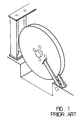
- the electrostatic precipitator utilizes a circular scraper for scraping off the greasy particles stuck on a circular electric plate.
- the scraper of the electrostatic precipitator is circular, it cannot be used for rectangular electric metal plates.
- the arrangement of the scraper in the precipitating zone affects the precipitating effects.
- Another object of the present invention is to provide an electrostatic precipitator in which it is possible to scrape greasy particles off the electric metal plates during precipitating without the need to stop the electrostatic precipitator, and the scrapers may be located at the corners of the precipitating zone in order not to affect the precipitating effects.
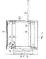
- the electrostatic precipitator according to the first preferred embodiment of the present invention comprises an ionization means 1, a precipitation means 2, a collecting means 3, a drive means 4, a cleaning means 5 and a housing 6 enclosing the above components.
- the precipitating means 2 is located to the rear of the ionization means 1 for precipitating particles in the current of gas flowing past from the ionization means 1.
- the precipitation means 2 includes at least one band type positive electric plate 21 having predetermined bends and a plurality of negative electric plates 22 distributed between every two adjacent sections of the positive electric sheet 21.
- the positive electric sheet 21 is a flexible laminated metal sheet connected to the positive pole so that they carry positive electric charges.
- On both sides of the positive electric sheet 21 are provided an insulated portion 23.
- the insulated portions 23 are coated with a layer of non-electric conductive film so that they do not carry positive electric charges.
- the drive means 4 includes a motor 41 and a plurality of guide wheels 43 pivotally provided on a frame 42 at predetermined positions.
- the motor 41 drives a drive wheel 44.
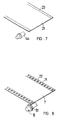
- Fig. 7 shows an example of the band type positive electric sheet 21.
- the insulated portions 23 thereof pass over the guide wheels 43 and the drive wheel 44 and enable the surface of the positive electric sheet 21 to have a certain tensile force.
- the entire positive electric sheet 21 may turn cyclically by means of the guide wheels 43.
- the negative electric plates 22 located between adjacent sections of the positive electric sheet 21 are mounted on the frame 42 of the drive means 4 and are arranged not to be in contact with the guide wheels 43 and the positive electric sheet 21 in order to avoid short circuit.
- the frame 42 is also made of insulated material.
- the cleaning means 5 is located at a predetermined position on the path of the positive electric sheet 21. In this preferred embodiment, the cleaning means 5 is disposed at a corner of the precipitating zone.
- the cleaning means 5 includes an inner scraper 51 and an outer scraper 52, both of which is made of insulated material.
- the inner and outer scrapers 51, 52 respectively contact the inner and outer surfaces of the positive electric sheet 21 so that they may scrape the greasy particles off the positive electric sheet 21 with a suitable friction.
- a scraping blade 53 capable of reciprocating in a linear manner is provided on the respective surfaces of the inner and outer scrapers 51, 52.
- the scraping blade 53 is driven by a pneumatic cylinder 54 for scraping the greasy particles from the surfaces of the inner and outer scrapers 51, 52.
- the collecting means 3 is located below the cleaning means 5 for receiving scraped greasy particles.
- the collecting means 3 may be removed from one side of the housing 6 for disposal.
- the greasy particles When greasy smoke or gas enters via an inlet 61 into the ionization means 1, the greasy particles will be ionized so that they carry negative electric charges. They then enter the electrostatic field where the positive electric sheet 21 and parallel negative electric plates 22 are. The charged greasy particles will adhere to the surfaces of the positive electric sheet 21.
- the positive electric sheet 21 As the positive electric sheet 21 is driven by the motor 41 to cyclically turn, it may always slidably contact the inner and outer scrapers 51, 52 to continually scrape the greasy particles off the positive electric sheets 21. The greasy particles will then adhere to the surfaces of the inner and outer scrapers 51, 52.
- the cylinder 54 At a set time for removing the greasy particles on the inner and outer scrapers 51, 52, the cylinder 54 will start operation and drive the respective scraping blades 53 of the inner and outer scrapers 51, 52 to scrape the greasy particles from the respective surfaces of the inner and outer scrapers 51, 52.
- the scraped greasy particles drop and are collected by the collecting means 3 below.
- the filtered gas will then be discharged through an outlet 62.
- the positive electric sheet 21 may be operated to remove greasy particles after the electrostatic precipitator has operated for some time. But if the electrostatic precipitator of the present invention is used in environments where there are lots of greasy smoke or gas, the positive electric sheet 21 may be operated simultaneously with the starting of the fan so that the greasy particles may be quickly removed before they may accumulate on the positive electric sheet 21. This helps to maintain the proper functioning of the positive electric sheet 21.
- FIG. 8 shows another example of the band type positive electric sheet.
- a positive electric sheet 7 is provided with an insulated portion 71 at both sides thereof.
- the insulated portion 71 is provided with a plurality of guide holes 72 equidistantly spaced apart from each other in a linear arrangement.
- a drive wheel 8 is provided with a plurality of cogs 81 which may engage the guide holes 72 of the insulated portion 71 for driving the positive electric sheet 7.
- the precipitation means of this embodiment includes a plurality of band type positive electric sheets 9 cycling separately and a plurality of negative electric plates 91 distributed between every two adjacent positive electric sheets 9.
- a cleaning means 92 is provided at each positive electric sheet 9 at a predetermined position.
- grounding metal plates 12 of the ionization means 1 may also be configured to be band type metal plates to achieve effects similar to those obtained by the configuration of band type positive electric sheets of the precipitation means.
- At least one nozzle may be provided to eject high-speed air currents to blow away the greasy particles on the inner and outer scrapers 51, 52 of the cleaning means 5.
Landscapes
- Electrostatic Separation (AREA)
Priority Applications (2)
| Application Number | Priority Date | Filing Date | Title |
|---|---|---|---|
| EP96305784A EP0823283A1 (fr) | 1996-08-06 | 1996-08-06 | Précipitateurs électrostatiques |
| EP97304840A EP0823284A1 (fr) | 1996-08-06 | 1997-07-01 | Précipitateurs électrostatiques |
Applications Claiming Priority (1)
| Application Number | Priority Date | Filing Date | Title |
|---|---|---|---|
| EP96305784A EP0823283A1 (fr) | 1996-08-06 | 1996-08-06 | Précipitateurs électrostatiques |
Publications (1)
| Publication Number | Publication Date |
|---|---|
| EP0823283A1 true EP0823283A1 (fr) | 1998-02-11 |
Family
ID=8225042
Family Applications (1)
| Application Number | Title | Priority Date | Filing Date |
|---|---|---|---|
| EP96305784A Withdrawn EP0823283A1 (fr) | 1996-08-06 | 1996-08-06 | Précipitateurs électrostatiques |
Country Status (1)
| Country | Link |
|---|---|
| EP (1) | EP0823283A1 (fr) |
Cited By (4)
| Publication number | Priority date | Publication date | Assignee | Title |
|---|---|---|---|---|
| CN103721848A (zh) * | 2014-01-03 | 2014-04-16 | 孟金来 | 径流式电除尘器及使用方法 |
| CN105457758A (zh) * | 2015-11-17 | 2016-04-06 | 吴新明 | 双孔带圈式静电实时自动净化空气装置 |
| CN105689145A (zh) * | 2016-04-14 | 2016-06-22 | 南京佳旺安环境科技有限公司 | 一种集尘板免振打静电除尘器 |
| CN118527255A (zh) * | 2024-07-24 | 2024-08-23 | 山东鲁腾环境技术有限公司 | 一种烟气脱硫脱硝除尘分离系统 |
Citations (6)
| Publication number | Priority date | Publication date | Assignee | Title |
|---|---|---|---|---|
| US4065275A (en) * | 1976-07-16 | 1977-12-27 | Nipponkai Heavy Industries Co., Ltd. | Electric dust precipitator |
| DE3108587A1 (de) * | 1980-03-06 | 1982-01-14 | Hitachi Plant Engineering & Construction Co., Ltd., Tokyo | Elektrostatischer staubabscheider |
| DE3418112A1 (de) * | 1984-05-16 | 1985-11-21 | Brown, Boveri & Cie Ag, 6800 Mannheim | Entstaubungsvorrichtung |
| WO1991009679A1 (fr) * | 1989-12-27 | 1991-07-11 | Louisiana-Pacific Corporation | Methode et appareil de separation electrostatique |
| US5437713A (en) * | 1994-12-01 | 1995-08-01 | Chang; Chin-Chu | Removal device for electrostatic precipitators |
| EP0703006A1 (fr) * | 1994-09-20 | 1996-03-27 | Chang, Chin-chu | Précipitateur électrostatique |
-
1996
- 1996-08-06 EP EP96305784A patent/EP0823283A1/fr not_active Withdrawn
Patent Citations (6)
| Publication number | Priority date | Publication date | Assignee | Title |
|---|---|---|---|---|
| US4065275A (en) * | 1976-07-16 | 1977-12-27 | Nipponkai Heavy Industries Co., Ltd. | Electric dust precipitator |
| DE3108587A1 (de) * | 1980-03-06 | 1982-01-14 | Hitachi Plant Engineering & Construction Co., Ltd., Tokyo | Elektrostatischer staubabscheider |
| DE3418112A1 (de) * | 1984-05-16 | 1985-11-21 | Brown, Boveri & Cie Ag, 6800 Mannheim | Entstaubungsvorrichtung |
| WO1991009679A1 (fr) * | 1989-12-27 | 1991-07-11 | Louisiana-Pacific Corporation | Methode et appareil de separation electrostatique |
| EP0703006A1 (fr) * | 1994-09-20 | 1996-03-27 | Chang, Chin-chu | Précipitateur électrostatique |
| US5437713A (en) * | 1994-12-01 | 1995-08-01 | Chang; Chin-Chu | Removal device for electrostatic precipitators |
Cited By (5)
| Publication number | Priority date | Publication date | Assignee | Title |
|---|---|---|---|---|
| CN103721848A (zh) * | 2014-01-03 | 2014-04-16 | 孟金来 | 径流式电除尘器及使用方法 |
| CN103721848B (zh) * | 2014-01-03 | 2016-03-16 | 孟金来 | 径流式电除尘器及使用方法 |
| CN105457758A (zh) * | 2015-11-17 | 2016-04-06 | 吴新明 | 双孔带圈式静电实时自动净化空气装置 |
| CN105689145A (zh) * | 2016-04-14 | 2016-06-22 | 南京佳旺安环境科技有限公司 | 一种集尘板免振打静电除尘器 |
| CN118527255A (zh) * | 2024-07-24 | 2024-08-23 | 山东鲁腾环境技术有限公司 | 一种烟气脱硫脱硝除尘分离系统 |
Similar Documents
| Publication | Publication Date | Title |
|---|---|---|
| US4185971A (en) | Electrostatic precipitator | |
| EP2424674B1 (fr) | Précipitateur électrostatique avec courroie de collecte | |
| CA1154694A (fr) | Precipitateur electrostatique de particules | |
| US5429669A (en) | Electrostatic precipitator | |
| JP3958020B2 (ja) | 電気集塵器 | |
| EP1721678B1 (fr) | Depoussiereur electrostatique | |
| EP0823283A1 (fr) | Précipitateurs électrostatiques | |
| US4940471A (en) | Device for cleaning two-stage electrostatic precipitators | |
| EP0515414B1 (fr) | Appareil de nettoyage de bandes | |
| EP0823284A1 (fr) | Précipitateurs électrostatiques | |
| JPH11290719A (ja) | 電気集塵装置 | |
| JP2004141826A (ja) | 電気集塵器 | |
| EP0703006A1 (fr) | Précipitateur électrostatique | |
| JP3667109B2 (ja) | 電気集じん機および電気集じん方法 | |
| US5149339A (en) | Rotary device for removing particulates from a gas stream | |
| CN1173400A (zh) | 静电集尘器 | |
| JP3042315U (ja) | 静電集塵器 | |
| JPH09248489A (ja) | 空気清浄装置 | |
| JPH1015432A (ja) | 空気清浄装置 | |
| JPH08155333A (ja) | 空気洗浄機 | |
| JPS6044976B2 (ja) | 電気集じん装置 | |
| WO1996031281A1 (fr) | Procede et appareil d'extraction de poussieres presentes dans des gaz | |
| KR19980074238A (ko) | 코로나 방전에 의한 정전여과포 집진방법 및 그 장치 | |
| CN218359949U (zh) | 清理上极板积尘的静电除尘装置 | |
| SU829139A1 (ru) | Электрофильтр |
Legal Events
| Date | Code | Title | Description |
|---|---|---|---|
| PUAI | Public reference made under article 153(3) epc to a published international application that has entered the european phase |
Free format text: ORIGINAL CODE: 0009012 |
|
| AK | Designated contracting states |
Kind code of ref document: A1 Designated state(s): AT BE CH DE DK ES FR GB GR IE IT LI NL SE |
|
| AKX | Designation fees paid | ||
| RBV | Designated contracting states (corrected) | ||
| STAA | Information on the status of an ep patent application or granted ep patent |
Free format text: STATUS: THE APPLICATION IS DEEMED TO BE WITHDRAWN |
|
| 18D | Application deemed to be withdrawn |
Effective date: 19980812 |