EP0823314A1 - Dispositif de verrouillage pour une machine à découper en tranches - Google Patents
Dispositif de verrouillage pour une machine à découper en tranches Download PDFInfo
- Publication number
- EP0823314A1 EP0823314A1 EP97202446A EP97202446A EP0823314A1 EP 0823314 A1 EP0823314 A1 EP 0823314A1 EP 97202446 A EP97202446 A EP 97202446A EP 97202446 A EP97202446 A EP 97202446A EP 0823314 A1 EP0823314 A1 EP 0823314A1
- Authority
- EP
- European Patent Office
- Prior art keywords
- cutting
- stop
- plate
- cutting member
- support table
- Prior art date
- Legal status (The legal status is an assumption and is not a legal conclusion. Google has not performed a legal analysis and makes no representation as to the accuracy of the status listed.)
- Withdrawn
Links
- 238000005520 cutting process Methods 0.000 claims abstract description 55
- 238000006073 displacement reaction Methods 0.000 claims description 6
- 230000004308 accommodation Effects 0.000 claims description 3
- 230000000903 blocking effect Effects 0.000 claims 3
- 230000001681 protective effect Effects 0.000 abstract description 16
- 238000004140 cleaning Methods 0.000 abstract description 4
- 230000000694 effects Effects 0.000 description 2
- 230000002411 adverse Effects 0.000 description 1
- 230000015572 biosynthetic process Effects 0.000 description 1
- 238000005266 casting Methods 0.000 description 1
- 238000000034 method Methods 0.000 description 1
- 238000003825 pressing Methods 0.000 description 1
- 235000013580 sausages Nutrition 0.000 description 1
- 239000000126 substance Substances 0.000 description 1
- 230000007704 transition Effects 0.000 description 1
Images


Classifications
-
- B—PERFORMING OPERATIONS; TRANSPORTING
- B26—HAND CUTTING TOOLS; CUTTING; SEVERING
- B26D—CUTTING; DETAILS COMMON TO MACHINES FOR PERFORATING, PUNCHING, CUTTING-OUT, STAMPING-OUT OR SEVERING
- B26D7/00—Details of apparatus for cutting, cutting-out, stamping-out, punching, perforating, or severing by means other than cutting
- B26D7/22—Safety devices specially adapted for cutting machines
- B26D7/225—Safety devices specially adapted for cutting machines for food slicers
-
- B—PERFORMING OPERATIONS; TRANSPORTING
- B26—HAND CUTTING TOOLS; CUTTING; SEVERING
- B26D—CUTTING; DETAILS COMMON TO MACHINES FOR PERFORATING, PUNCHING, CUTTING-OUT, STAMPING-OUT OR SEVERING
- B26D7/00—Details of apparatus for cutting, cutting-out, stamping-out, punching, perforating, or severing by means other than cutting
-
- B—PERFORMING OPERATIONS; TRANSPORTING
- B26—HAND CUTTING TOOLS; CUTTING; SEVERING
- B26D—CUTTING; DETAILS COMMON TO MACHINES FOR PERFORATING, PUNCHING, CUTTING-OUT, STAMPING-OUT OR SEVERING
- B26D7/00—Details of apparatus for cutting, cutting-out, stamping-out, punching, perforating, or severing by means other than cutting
- B26D7/01—Means for holding or positioning work
-
- B—PERFORMING OPERATIONS; TRANSPORTING
- B26—HAND CUTTING TOOLS; CUTTING; SEVERING
- B26D—CUTTING; DETAILS COMMON TO MACHINES FOR PERFORATING, PUNCHING, CUTTING-OUT, STAMPING-OUT OR SEVERING
- B26D7/00—Details of apparatus for cutting, cutting-out, stamping-out, punching, perforating, or severing by means other than cutting
- B26D7/06—Arrangements for feeding or delivering work of other than sheet, web, or filamentary form
- B26D7/0616—Arrangements for feeding or delivering work of other than sheet, web, or filamentary form by carriages, e.g. for slicing machines
-
- B—PERFORMING OPERATIONS; TRANSPORTING
- B26—HAND CUTTING TOOLS; CUTTING; SEVERING
- B26D—CUTTING; DETAILS COMMON TO MACHINES FOR PERFORATING, PUNCHING, CUTTING-OUT, STAMPING-OUT OR SEVERING
- B26D7/00—Details of apparatus for cutting, cutting-out, stamping-out, punching, perforating, or severing by means other than cutting
- B26D7/22—Safety devices specially adapted for cutting machines
-
- B—PERFORMING OPERATIONS; TRANSPORTING
- B26—HAND CUTTING TOOLS; CUTTING; SEVERING
- B26D—CUTTING; DETAILS COMMON TO MACHINES FOR PERFORATING, PUNCHING, CUTTING-OUT, STAMPING-OUT OR SEVERING
- B26D1/00—Cutting through work characterised by the nature or movement of the cutting member or particular materials not otherwise provided for; Apparatus or machines therefor; Cutting members therefor
- B26D1/01—Cutting through work characterised by the nature or movement of the cutting member or particular materials not otherwise provided for; Apparatus or machines therefor; Cutting members therefor involving a cutting member which does not travel with the work
- B26D1/12—Cutting through work characterised by the nature or movement of the cutting member or particular materials not otherwise provided for; Apparatus or machines therefor; Cutting members therefor involving a cutting member which does not travel with the work having a cutting member moving about an axis
- B26D1/14—Cutting through work characterised by the nature or movement of the cutting member or particular materials not otherwise provided for; Apparatus or machines therefor; Cutting members therefor involving a cutting member which does not travel with the work having a cutting member moving about an axis with a circular cutting member, e.g. disc cutter
- B26D1/143—Cutting through work characterised by the nature or movement of the cutting member or particular materials not otherwise provided for; Apparatus or machines therefor; Cutting members therefor involving a cutting member which does not travel with the work having a cutting member moving about an axis with a circular cutting member, e.g. disc cutter rotating about a stationary axis
-
- B—PERFORMING OPERATIONS; TRANSPORTING
- B26—HAND CUTTING TOOLS; CUTTING; SEVERING
- B26D—CUTTING; DETAILS COMMON TO MACHINES FOR PERFORATING, PUNCHING, CUTTING-OUT, STAMPING-OUT OR SEVERING
- B26D2210/00—Machines or methods used for cutting special materials
- B26D2210/02—Machines or methods used for cutting special materials for cutting food products, e.g. food slicers
Definitions
- the present invention relates to a cutting device in accordance with the preamble of Claim 1.
- a cutting device of this kind is known from DE-3,728,062 A1.
- the support table is designed such that it can be tilted away from the frame for the purpose of cleaning the various components.
- Recent safety regulations have made it necessary here for the thickness plate to function as a protective plate in the position in which the support table is removed, that is to say the protective plate has to broadly overlap the cutting edge of the cutting member so that, during cleaning, it is not possible for fingers or the like to come into contact with that part of the cutting member which is situated by the stop/protective plate.
- the object of the present invention is, firstly, to provide a cutting device which fulfils the abovementioned safety requirements, i.e. the stop plate can function as a protective plate in the cleaning position of the cutting device, i.e. on removal of the table.
- a further object of the present invention is to avoid the formation of the abovementioned gap between the support table and the cutting member during operation.
- the insight underlying the invention is to provide, in addition to the usual zero stop, a second "negative" stop of the adjustment means. This means that during removal of the support table, the stop/protective plate must be moved past the zero point of the operating position into the safety position in which the cutting edge of the cutting member is essentially covered by the thickness plate, which is then acting as a protective plate. Only then or after this can the table be removed or tilted away.
- the safety of the above-described device can be improved still further if the support table is taken off in stages.
- a first step there is a first, partial displacement away from the cutting member.
- cutting device can be used to cut all kinds of materials, such as foodstuffs and other substances.
- Fig. 1 shows a first embodiment of the cutting device according to the invention, denoted overall by 1.
- the cutting device comprises a frame 2 provided with legs 42.
- a guide 40 along which a carriage 39 provided with table 3 can be moved to and fro, is arranged on the frame 2.
- the device is used for cutting with a blade 4. It should be understood that any other cutting device, such as a saw, may be used instead of a blade.
- the table is provided with support bearings 41 and a guide rod 43, which is fastened to the frame 2.
- a conventional pressure plate 7 is arranged on the table 3.
- a cutting blade 4 which rotates with the aid of a motor 6, is arranged on the frame.
- a stop plate or protective plate 5 is present. The position of the thickness plate 5 determines the thickness of the product to be cut. This position is set with the aid of an adjustment knob 12.
- Table 3 can be removed from frame 2 and this removal takes place with the aid of a locking mechanism, of which handle 8 can be seen in Fig. 1.
- Fig. 2 shows a cross-section on line II-II in Fig. 1.
- the protective plate or thickness plate 5 is illustrated diagrammatically in the zero position, that is to say in the position in which the right-hand (in the drawing) part of this plate 5 is in line with cutting edge 9.
- the edge 10 of table 3, when moved against the thickness plate 5 may have a negligible clearance between it and the cutting blade 4. This is important since, as in the position illustrated in Fig. 5a, in which plate 5 lies at a distance from the cutting edge 9, the product to be cut, which in that figure is denoted by 11, is supported over as great a length as possible as far as the cutting edge 9. If there were to be any clearance between the edge 10 and cutting edge 9, the product 11 could be drawn into this gap and could lead to a less pleasing appearance of the product to be cut.
- Fig. 5b The position corresponding to Fig. 2 is illustrated in Fig. 5b. Moreover, it can be seen from Fig. 2 that handle 8 is adjoined by a pin 17, in line with which is situated an eccentric 19, which in turn is extended by a pin 18. Handle 8 can be moved in rotation and in translation. Eccentric 19 engages in an opening 38 in a clamping plate 21. This clamping plate is provided with a further opening 25 on the other side. This opening 25 is of stepped design with an inclined transition part 44. As can be seen from Fig. 4, table 3 is provided with a locking pin 22, in the region of the free end of which a recess 23 is formed, followed by a thickened end portion 24 lying at the free end. In the position shown in Fig.
- the "thickest" part of eccentric 19 is situated at the bottom, i.e. the clamping plate is moved downwards as far as possible, as a result of which that part of opening 25 which has the smallest diameter moves into the recess 23.
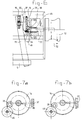
- Fig. 6 depicts the adjustment means for displacement of thickness plate 5 in more detail. It can be seen from this figure that thickness plate 5 interacts, via a pin part with rack 15, with a pinion 16, which is connected via an axle to a gearwheel 14. Gearwheel 14 is provided with an accommodation 20, which can be brought into line with an opening 37 formed in frame 40. Gearwheel 13 arranged on shaft 30, on the other hand, is connected to adjustment knob 12. Spring 45 is present, which tends to push the adjustment knob into the position shown in Fig. 6. As is also apparent from Figs. 7a and b, a stop sleeve 34 is present on gearwheel 14, which sleeve is provided with a first stop face 35 and a second stop face 36. By turning adjustment knob 12, rack 15 will move to and fro and the distance of the protective/thickness plate from the blade will vary.
- gearwheel 14 moves through opening 37. Further movement inwards is possible only if gearwheel 14 is situated in such a position that pin 18 can enter accommodation 20. To do this, it is necessary for gearwheel 14 to move from the position shown in Fig. 7a to the position shown in Fig. 7b. Movement of adjustment knob 12 out of the position shown in Fig. 7a is not possible without further measures, since first stop face 35 determines the limit position of the adjustment. Further rotation of the adjustment knob is possible only by moving knob 12 in the direction of arrow 32, as a result of which the stop edge 46 moves along the first stop face 35 and comes to lie in front of stop face 36, resulting in further play.
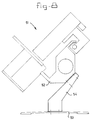
- the legs 42 are essentially perpendicular to the cutting member 4.
- FIG. 8 A design of this kind is shown in Fig. 8, in which 51 indicates the cutting device, 52 the frame and 54 the intermediate piece.
Landscapes
- Engineering & Computer Science (AREA)
- Life Sciences & Earth Sciences (AREA)
- Forests & Forestry (AREA)
- Mechanical Engineering (AREA)
- Food Science & Technology (AREA)
- Sawing (AREA)
Applications Claiming Priority (2)
| Application Number | Priority Date | Filing Date | Title |
|---|---|---|---|
| NL1003756A NL1003756C2 (nl) | 1996-08-07 | 1996-08-07 | Snijinrichting. |
| NL1003756 | 1996-08-07 |
Publications (1)
| Publication Number | Publication Date |
|---|---|
| EP0823314A1 true EP0823314A1 (fr) | 1998-02-11 |
Family
ID=19763332
Family Applications (1)
| Application Number | Title | Priority Date | Filing Date |
|---|---|---|---|
| EP97202446A Withdrawn EP0823314A1 (fr) | 1996-08-07 | 1997-08-07 | Dispositif de verrouillage pour une machine à découper en tranches |
Country Status (2)
| Country | Link |
|---|---|
| EP (1) | EP0823314A1 (fr) |
| NL (1) | NL1003756C2 (fr) |
Cited By (8)
| Publication number | Priority date | Publication date | Assignee | Title |
|---|---|---|---|---|
| WO2001045913A1 (fr) * | 1999-12-22 | 2001-06-28 | Premark Feg L.L.C. | Mecanisme de verrouillage pour trancheuse |
| EP0988940A3 (fr) * | 1998-09-25 | 2002-07-31 | Avery Berkel Limited | Machine à débiter en tranches |
| WO2007113019A1 (fr) * | 2006-03-31 | 2007-10-11 | BSH Bosch und Siemens Hausgeräte GmbH | Trancheuse universelle |
| WO2007103766A3 (fr) * | 2006-03-08 | 2007-10-25 | Premark Feg Llc | Trancheuse de produits alimentaires et systeme de verrouillage associe |
| WO2011157412A1 (fr) | 2010-06-19 | 2011-12-22 | Bizerba Gmbh & Co. Kg | Dispositif de coupe de tranches comportant un guide de chariot extérieur |
| WO2012059566A1 (fr) | 2010-11-05 | 2012-05-10 | Bizerba Gmbh & Co. Kg | Trancheuse à guidage de chariot extérieur et verrouillage de lame |
| WO2015189327A1 (fr) * | 2014-06-12 | 2015-12-17 | Bizerba Gmbh & Co. Kg | Découpeuse |
| DE102016114458A1 (de) * | 2016-08-04 | 2018-02-08 | Bizerba SE & Co. KG | Scheibenschneidemaschine mit einem in eine Reinigungslage bewegbaren Schlitten |
Citations (4)
| Publication number | Priority date | Publication date | Assignee | Title |
|---|---|---|---|---|
| DE3728062A1 (de) * | 1987-08-22 | 1989-03-02 | Graef Gmbh & Co Kg Maschinenba | Vorrichtung an allschnittschneidemaschinen zum schneidmesserschutz bei vom profilfuehrungskoerper voruebergehend abgezogenem schlitten |
| EP0386393A1 (fr) * | 1989-03-10 | 1990-09-12 | Angela Tognoli | Dispositif à trancher |
| EP0503168A1 (fr) * | 1991-03-11 | 1992-09-16 | Luis Arconada Arconada | Dispositif de sécurité pour machines de coupage à froid |
| DE4429628A1 (de) * | 1994-08-20 | 1996-02-22 | Bizerba Gmbh & Co Kg | Aufschnittschneidemaschine |
-
1996
- 1996-08-07 NL NL1003756A patent/NL1003756C2/nl not_active IP Right Cessation
-
1997
- 1997-08-07 EP EP97202446A patent/EP0823314A1/fr not_active Withdrawn
Patent Citations (4)
| Publication number | Priority date | Publication date | Assignee | Title |
|---|---|---|---|---|
| DE3728062A1 (de) * | 1987-08-22 | 1989-03-02 | Graef Gmbh & Co Kg Maschinenba | Vorrichtung an allschnittschneidemaschinen zum schneidmesserschutz bei vom profilfuehrungskoerper voruebergehend abgezogenem schlitten |
| EP0386393A1 (fr) * | 1989-03-10 | 1990-09-12 | Angela Tognoli | Dispositif à trancher |
| EP0503168A1 (fr) * | 1991-03-11 | 1992-09-16 | Luis Arconada Arconada | Dispositif de sécurité pour machines de coupage à froid |
| DE4429628A1 (de) * | 1994-08-20 | 1996-02-22 | Bizerba Gmbh & Co Kg | Aufschnittschneidemaschine |
Cited By (13)
| Publication number | Priority date | Publication date | Assignee | Title |
|---|---|---|---|---|
| EP0988940A3 (fr) * | 1998-09-25 | 2002-07-31 | Avery Berkel Limited | Machine à débiter en tranches |
| WO2001045913A1 (fr) * | 1999-12-22 | 2001-06-28 | Premark Feg L.L.C. | Mecanisme de verrouillage pour trancheuse |
| US8082830B2 (en) | 2006-03-08 | 2011-12-27 | Premark Feg L.L.C. | Food product slicer and associated interlock system |
| WO2007103766A3 (fr) * | 2006-03-08 | 2007-10-25 | Premark Feg Llc | Trancheuse de produits alimentaires et systeme de verrouillage associe |
| WO2007113019A1 (fr) * | 2006-03-31 | 2007-10-11 | BSH Bosch und Siemens Hausgeräte GmbH | Trancheuse universelle |
| WO2011157412A1 (fr) | 2010-06-19 | 2011-12-22 | Bizerba Gmbh & Co. Kg | Dispositif de coupe de tranches comportant un guide de chariot extérieur |
| DE102010024422A1 (de) | 2010-06-19 | 2011-12-22 | Bizerba Gmbh & Co. Kg | Scheibenschneidemaschine mit außen liegender Schlittenführung |
| US9156178B2 (en) | 2010-06-19 | 2015-10-13 | Bizerba Gmbh & Co. Kg | Slicing machine having an external carriage guide |
| WO2012059566A1 (fr) | 2010-11-05 | 2012-05-10 | Bizerba Gmbh & Co. Kg | Trancheuse à guidage de chariot extérieur et verrouillage de lame |
| DE102010050636A1 (de) | 2010-11-05 | 2012-05-10 | Bizerba Gmbh & Co Kg | Scheibenschneidemaschine mit außen liegender Schlittenführung und Messerverriegelung |
| US9327420B2 (en) | 2010-11-05 | 2016-05-03 | Bizerba Gmbh & Co. Kg | Slicing machine having an external carriage guide and knife locking |
| WO2015189327A1 (fr) * | 2014-06-12 | 2015-12-17 | Bizerba Gmbh & Co. Kg | Découpeuse |
| DE102016114458A1 (de) * | 2016-08-04 | 2018-02-08 | Bizerba SE & Co. KG | Scheibenschneidemaschine mit einem in eine Reinigungslage bewegbaren Schlitten |
Also Published As
| Publication number | Publication date |
|---|---|
| NL1003756C2 (nl) | 1998-02-12 |
Similar Documents
| Publication | Publication Date | Title |
|---|---|---|
| CN100548593C (zh) | 厨用刨刀 | |
| US5056388A (en) | Blind cutting machine | |
| US5638731A (en) | Chop saw arrangement | |
| US5231906A (en) | Table saw guard | |
| EP0502350B1 (fr) | Agencement de scie circulaire | |
| US5239756A (en) | Hand circular saw, particularly plunge saw | |
| US4334356A (en) | Anti-mar base for saber- and bayonet-type saws and the like | |
| CN100553838C (zh) | 具有顶台的斜切锯 | |
| EP1550525A2 (fr) | Une scie à onglet | |
| JPH05104501A (ja) | 積層された木材又はその類似物から成るワークを切断する方法及び装置 | |
| JPH1110606A (ja) | テーブルソー | |
| EP1033211A3 (fr) | Dispositif de serrage pour dispositif de protection d'une scie à table | |
| CA2362789A1 (fr) | Mecanisme de verrouillage pour trancheuse | |
| WO2001087551A2 (fr) | Trancheuse a poignee unitaire | |
| NL1003756C2 (nl) | Snijinrichting. | |
| EP0780181B1 (fr) | Chariot pour scie pivotante | |
| EP2039483B1 (fr) | Trancheuse de pain | |
| US4842031A (en) | Shaper guard | |
| EP0949048B1 (fr) | Scie à onglet à butée angulairement ajustable | |
| CA2152248C (fr) | Robot culinaire | |
| FR2608494A1 (fr) | Coupe-tout pour produits alimentaires | |
| JP3611452B2 (ja) | 丸鋸盤の切削粉排出機構 | |
| BE1003487A5 (fr) | Installation pour couper des tuiles de beton a l'etat vert. | |
| US20250187223A1 (en) | Bread slicer | |
| EP1621276B1 (fr) | Agencement d'une scie à onglet avec une capacité de coupe augmentée |
Legal Events
| Date | Code | Title | Description |
|---|---|---|---|
| PUAI | Public reference made under article 153(3) epc to a published international application that has entered the european phase |
Free format text: ORIGINAL CODE: 0009012 |
|
| AK | Designated contracting states |
Kind code of ref document: A1 Designated state(s): AT BE CH DE DK ES FI |
|
| 17P | Request for examination filed |
Effective date: 19980811 |
|
| AKX | Designation fees paid |
Free format text: AT BE CH DE DK ES LI |
|
| RBV | Designated contracting states (corrected) |
Designated state(s): AT BE CH DE DK ES LI |
|
| STAA | Information on the status of an ep patent application or granted ep patent |
Free format text: STATUS: THE APPLICATION IS DEEMED TO BE WITHDRAWN |
|
| 18D | Application deemed to be withdrawn |
Effective date: 20010301 |