EP2242146A2 - Dispositif de serrage ainsi que réglette coupe-circuit ou séparateur dotés d'un dispositif de serrage - Google Patents
Dispositif de serrage ainsi que réglette coupe-circuit ou séparateur dotés d'un dispositif de serrage Download PDFInfo
- Publication number
- EP2242146A2 EP2242146A2 EP10160092A EP10160092A EP2242146A2 EP 2242146 A2 EP2242146 A2 EP 2242146A2 EP 10160092 A EP10160092 A EP 10160092A EP 10160092 A EP10160092 A EP 10160092A EP 2242146 A2 EP2242146 A2 EP 2242146A2
- Authority
- EP
- European Patent Office
- Prior art keywords
- cage
- clamping
- yoke
- clamping structure
- recess
- Prior art date
- Legal status (The legal status is an assumption and is not a legal conclusion. Google has not performed a legal analysis and makes no representation as to the accuracy of the status listed.)
- Granted
Links
Images


Classifications
-
- H—ELECTRICITY
- H01—ELECTRIC ELEMENTS
- H01R—ELECTRICALLY-CONDUCTIVE CONNECTIONS; STRUCTURAL ASSOCIATIONS OF A PLURALITY OF MUTUALLY-INSULATED ELECTRICAL CONNECTING ELEMENTS; COUPLING DEVICES; CURRENT COLLECTORS
- H01R4/00—Electrically-conductive connections between two or more conductive members in direct contact, i.e. touching one another; Means for effecting or maintaining such contact; Electrically-conductive connections having two or more spaced connecting locations for conductors and using contact members penetrating insulation
- H01R4/28—Clamped connections, spring connections
- H01R4/30—Clamped connections, spring connections utilising a screw or nut clamping member
- H01R4/36—Conductive members located under tip of screw
- H01R4/363—Conductive members located under tip of screw with intermediate part between tip and conductive member
- H01R4/366—Conductive members located under tip of screw with intermediate part between tip and conductive member intermediate part attached to the tip of the screw
-
- H—ELECTRICITY
- H01—ELECTRIC ELEMENTS
- H01R—ELECTRICALLY-CONDUCTIVE CONNECTIONS; STRUCTURAL ASSOCIATIONS OF A PLURALITY OF MUTUALLY-INSULATED ELECTRICAL CONNECTING ELEMENTS; COUPLING DEVICES; CURRENT COLLECTORS
- H01R9/00—Structural associations of a plurality of mutually-insulated electrical connecting elements, e.g. terminal strips or terminal blocks; Terminals or binding posts mounted upon a base or in a case; Bases therefor
- H01R9/22—Bases, e.g. strip, block, panel
- H01R9/24—Terminal blocks
Definitions
- the present invention relates to a clamping structure for connecting cables to connecting rails and load-switching strips or disconnectors with such a clamping structure.
- Such a clamp construction is known, for example from the DE 44 35 057 ,
- the clamping structure described there has a closed clamping cage, through the bridge of a pressure pin accesses a pressure piece, so that with the help of the pressure piece after both terminal rail and cable have been arranged in the terminal cage, the cable can be pressed against the terminal rail.
- This clamping structure is intended for use on V-shaped connecting rails. It can not be used on flat connecting rails.
- the insertion of the cable in the terminal cage is very difficult to accomplish, especially for large cable cross-sections.
- the clamping cage To connect a cable to the connecting rail, the clamping cage must first be pushed onto the connecting rail or onto the cable. Then the corresponding cable must be brought in the direction of the axis of the connecting rail in the clamping cage. Only then you can clamp the pressure piece with the help of the pressure bolt on the one hand, and connecting rail on the other hand in the clamping cage.
- cables with large cross sections often have a very large bending radius. If these cables have already been assembled and routed, they usually can not be different in the longitudinal direction.
- the cable Although they can be moved transversely to the cable direction, e.g. However, a longitudinal displacement is usually not possible. Therefore, in order to connect with the aid of the described clamping structure, the cable must first be raised in the transverse direction and then bent accordingly in order to thread the cable end into the clamping cage. This bending, however, is difficult or impossible to accomplish with cables having large cable cross-sections.
- Another disadvantage of the known clamping structure is that the axial position of the clamping structure is not fixed. In other words, the clamping structure can be moved in the direction of the busbar axis or the cable axis during assembly. This can cause the terminal structure with other adjacent components comes into undesirable contact or that connecting rail or cable are no longer optimally clamped in the clamping cage. This is the case, for example, with some connection bars for disconnectors or safety edges customary to provide the connecting rail with a V-shaped connecting portion, which adjoins a substantially flat band-shaped portion.
- the clamping structure for this purpose has a substantially U-shaped cage bracket, which has two leg portions and a bottom portion connecting the leg portions, a cage yoke which substantially at the side facing away from the bottom portion of the leg portions connects to each other, so that between the cage yoke on the one hand and cage bracket on the other a cage cell is formed, a clamping piece disposed between the two leg portions in the cage cell, and a clamping plate disposed within the cage cell between the cage yoke and clamping piece, the clamping plate being reciprocable between an open position and a clamping position, and wherein the cage yoke from the cage bracket is removable.
- the clamping plate is connected to a threaded pin and the cage yoke has a threaded bore for receiving the threaded pin, so that when recorded in the threaded bore of the cage yoke threaded pin, the clamping plate can be brought by turning the threaded pin from the open position to a clamping position.
- This measure has the advantage that the clamping plate can be moved perpendicular to the cable axis by simply turning the threaded pin, which may be formed for example as a screw.
- by connecting the clamping plate with the threaded pin ensures that during disassembly by turning the grub screw in the opposite direction, the clamping plate can be easily detached from the cable.
- the pressure piece is not connected to the corresponding pressure pin, so that the pressure piece from the cable can not be solved by means of the pressure bolt, but must be removed manually during disassembly of this from the clamping cage.
- a terminal space for receiving a connecting rail is provided between the clamping piece and the bottom portion of the cage bracket.
- the clamping piece divides the cage cell into a terminal space and a cable space so that the clamping piece is arranged between the cable and the terminal rail.
- the clamping piece may be concave on its side facing the cable, so that the clamping piece better adapts to the outer contour of the cable, while the side facing away from the cable of the clamping piece can be adapted to the shape of the connecting rail.
- the clamping structure it is possible with the aid of the clamping structure to fix a cable to a connecting rail, which is originally provided for connection to the cable via corresponding pole shoes, which are screwed to the connecting rail.
- the two leg portions are formed cranked, so that the two leg sections at the end facing away from the bottom portion each have a projecting in the direction of the other leg portion portion, wherein the distance between the two projecting portions of the leg portions is smaller than the length of Käfigjochs, so that the cage yoke can not be removed or only by a bending apart of the leg portions of the bottom portion away from the cage bracket.
- This embodiment facilitates for some applications, the assembly and disassembly of the cable to the connecting rails.
- At least one leg section has a projection on its side facing the other leg section. This projection serves to hold the cage yoke in its substantially opposite to the bottom portion position of the leg portions. The cage yoke can be easily removed if the leg sections are bent slightly outwards.
- a leg portion may have a substantially U-shaped through hole surrounding a tongue portion, with the tongue portion toward the other Leg portion is bent and forms the projection.
- This can be formed in a cost effective manner, the projection. It is possible, for example, to form the cage bracket as a stamped and bent part.
- the object is achieved in that a corresponding terminal structure is provided in the load switch bar or the disconnector.
- the load switch bar or the separator may have a connection rail associated recess into which a push insert is inserted, wherein the push insert has a recess for receiving the clamping structure.
- the clamping structure is first inserted into the recess of the push insert.
- the push insert is inserted together with the terminal structure in the corresponding recess of the load switch bar or the disconnector.
- the recess in the connecting rail is designed such that when inserting the push insert, the connecting rail extends into the terminal space of the clamping structure. Now, only the cable must be applied to the clamping piece and the clamping plate are brought into the clamping position.
- the push insert on a stop element, which prevents a displacement of the clamping structure relative to the push insert in the direction of the recess or in the opposite direction.
- a stop element which prevents a displacement of the clamping structure relative to the push insert in the direction of the recess or in the opposite direction.
- two stop elements are provided which receive the clamping structure such that a relative movement in the direction of the recess and in the opposite direction is prevented.
- the push insert and / or the recess in the load switch bar or the separator has a movable or deformable locking element and the recess in the load switch bar or the separator and / or the push insert has a recess for receiving the latching element.
- the push insert is pushed into the corresponding recess until the locking element engages in the recess. Now the push insert is in the exact position and the assembly can be done.
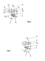
- FIG. 1 a first embodiment of a clamping structure according to the invention is shown.
- the clamping structure has a substantially U-shaped cage bracket 1, which has two leg sections 2, 3 and a bottom section 4 connecting the leg sections 2, 3. Furthermore, a cage yoke 5 is provided, which substantially at the side facing away from the bottom portion 4 of the leg sections 2, 3 connects to each other, so that between the cage yoke 5 on the one hand and cage bracket 1 on the other hand, a space is formed, which is also called cage cell below.
- a clamping piece 6 is arranged between the two leg sections 2, 3. This clamping piece 6 divides the cage cell into a terminal space 7 for a connecting rail and a cable space 8 for receiving the cable.
- connection space 7 is essentially limited by the clamping piece 6 and the bottom portion 4, while the cable space 8 is bounded by the clamping piece 6, the two leg portions 2, 3 and the cage yoke 5.
- the cage yoke 5 has a threaded through bore through which a threaded pin 9 is connected to a clamping plate 10 which is arranged in the cable space 8. By turning the threaded pin 9, the clamping plate 10 can be moved in the direction of the clamping piece 6 or away from it.
- the two leg sections 2, 3 have two cranked sections 11, 12 at their end facing away from the bottom section 4. These cranked portions 11, 12 are formed such that the distance between them is slightly smaller than the corresponding extent of the cage yoke 5, so that in the in FIG.
- both legs have an approximately U-shaped recess 13 which surrounds a corresponding tongue portion 14.
- This tongue portion 14 has been bent in the production something in the direction of the cage cell, so that in the in FIG. 1 shown position the cage yoke 5 on both sides of the corresponding tongue portion 14 is supported.
- the leg sections must be bent slightly outwards, or the cage yoke must be pushed forward (or rearward).
- the in FIG. 1 shown embodiment is provided for connection to substantially flat connecting rails, therefore, the terminal compartment 7 is formed according to the rail shape.
- FIG. 2 therefore, another embodiment is shown which differs from the embodiment of FIG. 1 essentially differs in that clamping piece 6 on the one hand and bottom section 4 on the other hand are deviating shaped to receive a substantially V-shaped connecting rail.
- the clamping piece 6 is provided between the connecting rail and cable, so that the clamping piece 6 may be formed concave on its side facing the cable space to adapt to the shape of the cable, and at the terminal space side facing the expected shape of the Connecting rail can be formed.
- FIG. 3 an embodiment of a push insert is shown.
- the push insert 15 has a recess 16, in which the bottom portion 4 of the clamping structure can be used.
- the recess 16 is bounded by lateral cheeks 18, 19 and a front stop surface 17.
- the push insert on two locking elements 20 which are elastically deformable.
- the push insert 15 has a recess 21 for receiving a fastening nut. If the push insert together with the in FIG. 1 used clamp construction, so it is not necessary to arrange a nut in the recess 21.
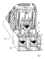
- FIG. 4 is a perspective view of a corresponding switching strip 22 is shown.
- This switching strip 22 has three connecting rails, which must be connected with appropriate cables. Therefore, refer to the corresponding connection bars in the in FIG. 4 already shown the corresponding U-shaped cage bracket 1, 1 'and 1 "placed
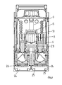
- FIG. 5 is another perspective view of the switching strip 22 can be seen. In this view, the substantially band-shaped connecting rails 23 are clearly visible. These are already arranged in the corresponding connection space 7 of the clamping structure.
- the cage yoke 5 is mounted on the cage bracket 1.
- the cables can either be in the in FIG. 5 shown position or in the FIG. 4 Position are introduced into the cage cell.
- FIG. 6 shows a sectional view through the embodiment of FIG.
- the insertion direction is in FIG. 3 marked with an arrow.
- the corresponding locking elements 20 then engage in corresponding recesses 25 in the recess 24 of the switching strip 22, so that the push insert 15 is positioned relative to the switching strip 22.
- the clamping structure has exactly the correct position in the FIGS. 4 to 6 is shown.
- the cable if necessary, after previous removal of the cage yoke 5, are easily introduced into the cable space 8.
- the clamping plate 10 can then be moved in the direction of the clamping piece 6, so that the cable is securely clamped securely in the cable compartment 8 and the connecting rail 23 in the terminal compartment 7.
- the connecting rails are designed to be used with pole pieces.
- the clamping structure 1 together with the push insert 15 is pulled out of the recess 24.
- the clamp assembly is removed and a nut inserted into the corresponding recess 21 of the drawer insert 15.
- the push insert 15 can be inserted again into the corresponding recess 24.
- the connecting rails 23 already have through holes 26, so that it is easily possible to put the pole pieces on the nut received in the recess 21 and by means of a screw which passes through both pole piece and through hole 26 in the connecting rail 23, with the mother in connect the recess 21 and thus to connect the cable lugs firmly to the connecting rail.
Landscapes
- Connections Arranged To Contact A Plurality Of Conductors (AREA)
- Installation Of Indoor Wiring (AREA)
- Details Of Indoor Wiring (AREA)
Applications Claiming Priority (1)
| Application Number | Priority Date | Filing Date | Title |
|---|---|---|---|
| DE102009002470A DE102009002470A1 (de) | 2009-04-17 | 2009-04-17 | Klemmaufbau sowie Lastschaltleiste oder Trenner mit Klemmaufbau |
Publications (3)
| Publication Number | Publication Date |
|---|---|
| EP2242146A2 true EP2242146A2 (fr) | 2010-10-20 |
| EP2242146A3 EP2242146A3 (fr) | 2014-04-16 |
| EP2242146B1 EP2242146B1 (fr) | 2016-06-29 |
Family
ID=42320065
Family Applications (1)
| Application Number | Title | Priority Date | Filing Date |
|---|---|---|---|
| EP10160092.2A Active EP2242146B1 (fr) | 2009-04-17 | 2010-04-15 | Réglette coupe-circuit ou séparateur dotés d'un dispositif de serrage |
Country Status (4)
| Country | Link |
|---|---|
| EP (1) | EP2242146B1 (fr) |
| DE (1) | DE102009002470A1 (fr) |
| ES (1) | ES2589379T3 (fr) |
| PL (1) | PL2242146T3 (fr) |
Cited By (3)
| Publication number | Priority date | Publication date | Assignee | Title |
|---|---|---|---|---|
| CN105375136A (zh) * | 2015-10-28 | 2016-03-02 | 国家电网公司 | 电力电缆用快速连接器 |
| EP3018759A1 (fr) | 2014-11-10 | 2016-05-11 | Elektro-Bauelemente GmbH | Cadre de serrage, borne de contact électrique et procédé de fabrication associé |
| CN106911054A (zh) * | 2017-04-01 | 2017-06-30 | 菲尼克斯亚太电气(南京)有限公司 | 一种外置式开关螺钉转接组件 |
Citations (1)
| Publication number | Priority date | Publication date | Assignee | Title |
|---|---|---|---|---|
| DE4435057A1 (de) | 1994-09-30 | 1996-04-04 | Efen Elektrotech Fab | Klemmaufbau zum Anschließen von Kabeln an Schienen |
Family Cites Families (12)
| Publication number | Priority date | Publication date | Assignee | Title |
|---|---|---|---|---|
| DE1200407B (de) * | 1958-09-26 | 1965-09-09 | Siemens Ag | Klemme fuer elektrische Leiter |
| FR1229919A (fr) * | 1959-03-25 | 1960-09-12 | Cie De Construction Electr | Borne de connexion |
| FR77617E (fr) * | 1960-04-26 | 1962-03-30 | Materiel Electr Soc Ind De | Raccord pour câbles électriques |
| SE346427B (fr) * | 1968-02-20 | 1972-07-03 | Asea Ab | |
| FR2058441A5 (fr) * | 1969-09-04 | 1971-05-28 | Sicame Sa | |
| DE7317383U (de) * | 1973-05-09 | 1973-09-13 | Geyer Ch | Kabelklemme |
| FR2427698A1 (fr) * | 1978-05-30 | 1979-12-28 | Arnould App Electr | Raccord de conducteurs electriques |
| DE19833150C1 (de) * | 1998-07-23 | 1999-10-14 | Moeller Gmbh | Anschlußklemme |
| AU1161700A (en) * | 1998-12-18 | 2000-07-12 | Moeller Gmbh | Connecting terminal |
| DE10013157B4 (de) * | 2000-03-17 | 2008-02-14 | Aeg Niederspannungstechnik Gmbh & Co Kg | Anschlusskontaktsystem |
| DE20318855U1 (de) * | 2003-12-05 | 2004-02-26 | Moeller Gmbh | Anschlußmodul für Leistungsschalter |
| EP2063491B1 (fr) * | 2007-11-23 | 2012-01-11 | Jean Müller GmbH Elektrotechnische Fabrik | Pince de raccordement pour un transformateur |
-
2009
- 2009-04-17 DE DE102009002470A patent/DE102009002470A1/de active Pending
-
2010
- 2010-04-15 PL PL10160092.2T patent/PL2242146T3/pl unknown
- 2010-04-15 EP EP10160092.2A patent/EP2242146B1/fr active Active
- 2010-04-15 ES ES10160092.2T patent/ES2589379T3/es active Active
Patent Citations (1)
| Publication number | Priority date | Publication date | Assignee | Title |
|---|---|---|---|---|
| DE4435057A1 (de) | 1994-09-30 | 1996-04-04 | Efen Elektrotech Fab | Klemmaufbau zum Anschließen von Kabeln an Schienen |
Cited By (5)
| Publication number | Priority date | Publication date | Assignee | Title |
|---|---|---|---|---|
| EP3018759A1 (fr) | 2014-11-10 | 2016-05-11 | Elektro-Bauelemente GmbH | Cadre de serrage, borne de contact électrique et procédé de fabrication associé |
| DE102014116353A1 (de) | 2014-11-10 | 2016-05-12 | Elektro-Bauelemente Gmbh | Klemmrahmen, elektrische Kontaktklemme und Herstellverfahren hierfür |
| CN105375136A (zh) * | 2015-10-28 | 2016-03-02 | 国家电网公司 | 电力电缆用快速连接器 |
| CN106911054A (zh) * | 2017-04-01 | 2017-06-30 | 菲尼克斯亚太电气(南京)有限公司 | 一种外置式开关螺钉转接组件 |
| CN106911054B (zh) * | 2017-04-01 | 2024-03-19 | 菲尼克斯亚太电气(南京)有限公司 | 一种外置式开关螺钉转接组件 |
Also Published As
| Publication number | Publication date |
|---|---|
| DE102009002470A1 (de) | 2010-10-21 |
| EP2242146A3 (fr) | 2014-04-16 |
| ES2589379T3 (es) | 2016-11-14 |
| EP2242146B1 (fr) | 2016-06-29 |
| PL2242146T3 (pl) | 2016-12-30 |
Similar Documents
| Publication | Publication Date | Title |
|---|---|---|
| EP1956684B1 (fr) | Contact universel | |
| EP2729991B1 (fr) | Borne de connexion | |
| EP2019449B1 (fr) | Borne de connexion à vis et son procédé de fabrication | |
| DE10161248B4 (de) | Kastenartige Anschlussklemme einer elektrischen Vorrichtung | |
| DE4408985B4 (de) | Elektrische Einrichtung, insbesondere Reihenklemme, mit einer Klemme für eine Schnellverbindung | |
| EP0334975B1 (fr) | Connexion de conducteur | |
| EP0823752A2 (fr) | Connecteur à ressort pour conducteur électrique | |
| DE102006037720A1 (de) | Vorrichtung zum elektrischen Verbinden von midestens zwei Hauptleitern eines Energieversorgungskabels, insbesondere Kabelabzweigklemme | |
| DE1083888B (de) | Elektrische Klemmleiste | |
| DE102020128775B4 (de) | Leiteranschlussklemme in Form eines Verteilerklemmenblocks | |
| DE2619035C2 (de) | Schraubenlose Anschluß- und/oder Verbindungsklemme | |
| EP2242146B1 (fr) | Réglette coupe-circuit ou séparateur dotés d'un dispositif de serrage | |
| DE112008001919B4 (de) | Isolierter Kabelverbinder | |
| DE102018206849B4 (de) | Vorrichtung zur klemmenden Befestigung | |
| DE4138547C1 (en) | Pole terminal clamp esp. for car battery - has inclined surface formed on small end face of at least one bowed flange extending in parallel to axis of recess in flat material part | |
| WO2011128205A1 (fr) | Dispositif de raccordement | |
| EP0809325A1 (fr) | Dispositif d'installation électrique et borne de connexion pour le dispositif | |
| EP0704931B1 (fr) | Dispositif de serrage pour la connexion des câbles à des barres | |
| DE102007030061A1 (de) | Elektrische Hilfsverbindung zur Verbindung von wenigstens zwei Anschlussblöcken | |
| EP3995705A1 (fr) | Dispositif de fixation à un élément oblong | |
| EP3855572A1 (fr) | Borne de liaison | |
| DE102020008160A1 (de) | Leiteranschlussklemme in Form eines Verteilerklemmenblocks | |
| DE102021105362A1 (de) | Frontschraubklemme | |
| EP3826113B1 (fr) | Borne de raccordement de conducteur | |
| DE202014101428U1 (de) | Kontaktbuchse für eine Steckdose oder Kupplung |
Legal Events
| Date | Code | Title | Description |
|---|---|---|---|
| PUAI | Public reference made under article 153(3) epc to a published international application that has entered the european phase |
Free format text: ORIGINAL CODE: 0009012 |
|
| AK | Designated contracting states |
Kind code of ref document: A2 Designated state(s): AT BE BG CH CY CZ DE DK EE ES FI FR GB GR HR HU IE IS IT LI LT LU LV MC MK MT NL NO PL PT RO SE SI SK SM TR |
|
| AX | Request for extension of the european patent |
Extension state: AL BA ME RS |
|
| PUAL | Search report despatched |
Free format text: ORIGINAL CODE: 0009013 |
|
| AK | Designated contracting states |
Kind code of ref document: A3 Designated state(s): AT BE BG CH CY CZ DE DK EE ES FI FR GB GR HR HU IE IS IT LI LT LU LV MC MK MT NL NO PL PT RO SE SI SK SM TR |
|
| AX | Request for extension of the european patent |
Extension state: AL BA ME RS |
|
| RIC1 | Information provided on ipc code assigned before grant |
Ipc: H01R 4/36 20060101AFI20140310BHEP Ipc: H01R 9/24 20060101ALN20140310BHEP |
|
| 17P | Request for examination filed |
Effective date: 20141009 |
|
| RBV | Designated contracting states (corrected) |
Designated state(s): AT BE BG CH CY CZ DE DK EE ES FI FR GB GR HR HU IE IS IT LI LT LU LV MC MK MT NL NO PL PT RO SE SI SK SM TR |
|
| GRAP | Despatch of communication of intention to grant a patent |
Free format text: ORIGINAL CODE: EPIDOSNIGR1 |
|
| INTG | Intention to grant announced |
Effective date: 20160122 |
|
| GRAS | Grant fee paid |
Free format text: ORIGINAL CODE: EPIDOSNIGR3 |
|
| GRAA | (expected) grant |
Free format text: ORIGINAL CODE: 0009210 |
|
| AK | Designated contracting states |
Kind code of ref document: B1 Designated state(s): AT BE BG CH CY CZ DE DK EE ES FI FR GB GR HR HU IE IS IT LI LT LU LV MC MK MT NL NO PL PT RO SE SI SK SM TR |
|
| REG | Reference to a national code |
Ref country code: GB Ref legal event code: FG4D Free format text: NOT ENGLISH |
|
| REG | Reference to a national code |
Ref country code: CH Ref legal event code: EP |
|
| REG | Reference to a national code |
Ref country code: AT Ref legal event code: REF Ref document number: 809754 Country of ref document: AT Kind code of ref document: T Effective date: 20160715 |
|
| REG | Reference to a national code |
Ref country code: IE Ref legal event code: FG4D Free format text: LANGUAGE OF EP DOCUMENT: GERMAN |
|
| REG | Reference to a national code |
Ref country code: CH Ref legal event code: NV Representative=s name: ISLER AND PEDRAZZINI AG, CH |
|
| REG | Reference to a national code |
Ref country code: DE Ref legal event code: R096 Ref document number: 502010011899 Country of ref document: DE |
|
| REG | Reference to a national code |
Ref country code: NL Ref legal event code: FP |
|
| REG | Reference to a national code |
Ref country code: SE Ref legal event code: TRGR |
|
| REG | Reference to a national code |
Ref country code: LT Ref legal event code: MG4D |
|
| PG25 | Lapsed in a contracting state [announced via postgrant information from national office to epo] |
Ref country code: FI Free format text: LAPSE BECAUSE OF FAILURE TO SUBMIT A TRANSLATION OF THE DESCRIPTION OR TO PAY THE FEE WITHIN THE PRESCRIBED TIME-LIMIT Effective date: 20160629 Ref country code: LT Free format text: LAPSE BECAUSE OF FAILURE TO SUBMIT A TRANSLATION OF THE DESCRIPTION OR TO PAY THE FEE WITHIN THE PRESCRIBED TIME-LIMIT Effective date: 20160629 Ref country code: NO Free format text: LAPSE BECAUSE OF FAILURE TO SUBMIT A TRANSLATION OF THE DESCRIPTION OR TO PAY THE FEE WITHIN THE PRESCRIBED TIME-LIMIT Effective date: 20160929 |
|
| REG | Reference to a national code |
Ref country code: ES Ref legal event code: FG2A Ref document number: 2589379 Country of ref document: ES Kind code of ref document: T3 Effective date: 20161114 |
|
| PG25 | Lapsed in a contracting state [announced via postgrant information from national office to epo] |
Ref country code: HR Free format text: LAPSE BECAUSE OF FAILURE TO SUBMIT A TRANSLATION OF THE DESCRIPTION OR TO PAY THE FEE WITHIN THE PRESCRIBED TIME-LIMIT Effective date: 20160629 Ref country code: LV Free format text: LAPSE BECAUSE OF FAILURE TO SUBMIT A TRANSLATION OF THE DESCRIPTION OR TO PAY THE FEE WITHIN THE PRESCRIBED TIME-LIMIT Effective date: 20160629 Ref country code: GR Free format text: LAPSE BECAUSE OF FAILURE TO SUBMIT A TRANSLATION OF THE DESCRIPTION OR TO PAY THE FEE WITHIN THE PRESCRIBED TIME-LIMIT Effective date: 20160930 |
|
| PG25 | Lapsed in a contracting state [announced via postgrant information from national office to epo] |
Ref country code: IT Free format text: LAPSE BECAUSE OF FAILURE TO SUBMIT A TRANSLATION OF THE DESCRIPTION OR TO PAY THE FEE WITHIN THE PRESCRIBED TIME-LIMIT Effective date: 20160629 Ref country code: IS Free format text: LAPSE BECAUSE OF FAILURE TO SUBMIT A TRANSLATION OF THE DESCRIPTION OR TO PAY THE FEE WITHIN THE PRESCRIBED TIME-LIMIT Effective date: 20161029 Ref country code: CZ Free format text: LAPSE BECAUSE OF FAILURE TO SUBMIT A TRANSLATION OF THE DESCRIPTION OR TO PAY THE FEE WITHIN THE PRESCRIBED TIME-LIMIT Effective date: 20160629 Ref country code: EE Free format text: LAPSE BECAUSE OF FAILURE TO SUBMIT A TRANSLATION OF THE DESCRIPTION OR TO PAY THE FEE WITHIN THE PRESCRIBED TIME-LIMIT Effective date: 20160629 Ref country code: RO Free format text: LAPSE BECAUSE OF FAILURE TO SUBMIT A TRANSLATION OF THE DESCRIPTION OR TO PAY THE FEE WITHIN THE PRESCRIBED TIME-LIMIT Effective date: 20160629 Ref country code: SK Free format text: LAPSE BECAUSE OF FAILURE TO SUBMIT A TRANSLATION OF THE DESCRIPTION OR TO PAY THE FEE WITHIN THE PRESCRIBED TIME-LIMIT Effective date: 20160629 |
|
| PG25 | Lapsed in a contracting state [announced via postgrant information from national office to epo] |
Ref country code: SM Free format text: LAPSE BECAUSE OF FAILURE TO SUBMIT A TRANSLATION OF THE DESCRIPTION OR TO PAY THE FEE WITHIN THE PRESCRIBED TIME-LIMIT Effective date: 20160629 Ref country code: PT Free format text: LAPSE BECAUSE OF FAILURE TO SUBMIT A TRANSLATION OF THE DESCRIPTION OR TO PAY THE FEE WITHIN THE PRESCRIBED TIME-LIMIT Effective date: 20161031 |
|
| REG | Reference to a national code |
Ref country code: DE Ref legal event code: R097 Ref document number: 502010011899 Country of ref document: DE |
|
| PLBE | No opposition filed within time limit |
Free format text: ORIGINAL CODE: 0009261 |
|
| STAA | Information on the status of an ep patent application or granted ep patent |
Free format text: STATUS: NO OPPOSITION FILED WITHIN TIME LIMIT |
|
| PG25 | Lapsed in a contracting state [announced via postgrant information from national office to epo] |
Ref country code: DK Free format text: LAPSE BECAUSE OF FAILURE TO SUBMIT A TRANSLATION OF THE DESCRIPTION OR TO PAY THE FEE WITHIN THE PRESCRIBED TIME-LIMIT Effective date: 20160629 |
|
| 26N | No opposition filed |
Effective date: 20170330 |
|
| PG25 | Lapsed in a contracting state [announced via postgrant information from national office to epo] |
Ref country code: SI Free format text: LAPSE BECAUSE OF FAILURE TO SUBMIT A TRANSLATION OF THE DESCRIPTION OR TO PAY THE FEE WITHIN THE PRESCRIBED TIME-LIMIT Effective date: 20160629 Ref country code: BG Free format text: LAPSE BECAUSE OF FAILURE TO SUBMIT A TRANSLATION OF THE DESCRIPTION OR TO PAY THE FEE WITHIN THE PRESCRIBED TIME-LIMIT Effective date: 20160929 |
|
| GBPC | Gb: european patent ceased through non-payment of renewal fee |
Effective date: 20170415 |
|
| REG | Reference to a national code |
Ref country code: IE Ref legal event code: MM4A |
|
| REG | Reference to a national code |
Ref country code: FR Ref legal event code: ST Effective date: 20171229 |
|
| PG25 | Lapsed in a contracting state [announced via postgrant information from national office to epo] |
Ref country code: FR Free format text: LAPSE BECAUSE OF NON-PAYMENT OF DUE FEES Effective date: 20170502 Ref country code: MC Free format text: LAPSE BECAUSE OF FAILURE TO SUBMIT A TRANSLATION OF THE DESCRIPTION OR TO PAY THE FEE WITHIN THE PRESCRIBED TIME-LIMIT Effective date: 20160629 |
|
| PG25 | Lapsed in a contracting state [announced via postgrant information from national office to epo] |
Ref country code: LU Free format text: LAPSE BECAUSE OF NON-PAYMENT OF DUE FEES Effective date: 20170415 Ref country code: GB Free format text: LAPSE BECAUSE OF NON-PAYMENT OF DUE FEES Effective date: 20170415 |
|
| REG | Reference to a national code |
Ref country code: BE Ref legal event code: MM Effective date: 20170430 |
|
| PG25 | Lapsed in a contracting state [announced via postgrant information from national office to epo] |
Ref country code: IE Free format text: LAPSE BECAUSE OF NON-PAYMENT OF DUE FEES Effective date: 20170415 |
|
| PG25 | Lapsed in a contracting state [announced via postgrant information from national office to epo] |
Ref country code: BE Free format text: LAPSE BECAUSE OF NON-PAYMENT OF DUE FEES Effective date: 20170430 |
|
| PG25 | Lapsed in a contracting state [announced via postgrant information from national office to epo] |
Ref country code: MT Free format text: LAPSE BECAUSE OF FAILURE TO SUBMIT A TRANSLATION OF THE DESCRIPTION OR TO PAY THE FEE WITHIN THE PRESCRIBED TIME-LIMIT Effective date: 20160629 |
|
| PG25 | Lapsed in a contracting state [announced via postgrant information from national office to epo] |
Ref country code: HU Free format text: LAPSE BECAUSE OF FAILURE TO SUBMIT A TRANSLATION OF THE DESCRIPTION OR TO PAY THE FEE WITHIN THE PRESCRIBED TIME-LIMIT; INVALID AB INITIO Effective date: 20100415 |
|
| PG25 | Lapsed in a contracting state [announced via postgrant information from national office to epo] |
Ref country code: CY Free format text: LAPSE BECAUSE OF NON-PAYMENT OF DUE FEES Effective date: 20160629 |
|
| PG25 | Lapsed in a contracting state [announced via postgrant information from national office to epo] |
Ref country code: MK Free format text: LAPSE BECAUSE OF FAILURE TO SUBMIT A TRANSLATION OF THE DESCRIPTION OR TO PAY THE FEE WITHIN THE PRESCRIBED TIME-LIMIT Effective date: 20160629 |
|
| PGFP | Annual fee paid to national office [announced via postgrant information from national office to epo] |
Ref country code: TR Payment date: 20240321 Year of fee payment: 15 |
|
| PGFP | Annual fee paid to national office [announced via postgrant information from national office to epo] |
Ref country code: ES Payment date: 20240503 Year of fee payment: 15 |
|
| PGFP | Annual fee paid to national office [announced via postgrant information from national office to epo] |
Ref country code: AT Payment date: 20240320 Year of fee payment: 15 |
|
| PGFP | Annual fee paid to national office [announced via postgrant information from national office to epo] |
Ref country code: SE Payment date: 20240427 Year of fee payment: 15 |
|
| PGFP | Annual fee paid to national office [announced via postgrant information from national office to epo] |
Ref country code: PL Payment date: 20250324 Year of fee payment: 16 |
|
| PGFP | Annual fee paid to national office [announced via postgrant information from national office to epo] |
Ref country code: NL Payment date: 20250427 Year of fee payment: 16 |
|
| PGFP | Annual fee paid to national office [announced via postgrant information from national office to epo] |
Ref country code: DE Payment date: 20250429 Year of fee payment: 16 |
|
| PGFP | Annual fee paid to national office [announced via postgrant information from national office to epo] |
Ref country code: CH Payment date: 20250501 Year of fee payment: 16 |
|
| REG | Reference to a national code |
Ref country code: SE Ref legal event code: EUG |
|
| REG | Reference to a national code |
Ref country code: AT Ref legal event code: MM01 Ref document number: 809754 Country of ref document: AT Kind code of ref document: T Effective date: 20250415 |
|
| PG25 | Lapsed in a contracting state [announced via postgrant information from national office to epo] |
Ref country code: AT Free format text: LAPSE BECAUSE OF NON-PAYMENT OF DUE FEES Effective date: 20250415 |
|
| PG25 | Lapsed in a contracting state [announced via postgrant information from national office to epo] |
Ref country code: SE Free format text: LAPSE BECAUSE OF NON-PAYMENT OF DUE FEES Effective date: 20250416 |