EP0823955B1 - Appareil pour executer un travail a l'aide d'un outil - Google Patents
Appareil pour executer un travail a l'aide d'un outil Download PDFInfo
- Publication number
- EP0823955B1 EP0823955B1 EP96915081A EP96915081A EP0823955B1 EP 0823955 B1 EP0823955 B1 EP 0823955B1 EP 96915081 A EP96915081 A EP 96915081A EP 96915081 A EP96915081 A EP 96915081A EP 0823955 B1 EP0823955 B1 EP 0823955B1
- Authority
- EP
- European Patent Office
- Prior art keywords
- tool
- actuator
- carrying member
- advance
- resistance
- Prior art date
- Legal status (The legal status is an assumption and is not a legal conclusion. Google has not performed a legal analysis and makes no representation as to the accuracy of the status listed.)
- Expired - Lifetime
Links
- 238000009527 percussion Methods 0.000 claims abstract description 33
- 239000012530 fluid Substances 0.000 claims abstract description 27
- 239000011435 rock Substances 0.000 claims abstract description 14
- 230000002085 persistent effect Effects 0.000 claims description 8
- 239000000463 material Substances 0.000 claims description 7
- 239000007787 solid Substances 0.000 claims description 6
- 238000000034 method Methods 0.000 claims description 4
- 230000000977 initiatory effect Effects 0.000 claims description 2
- 239000003921 oil Substances 0.000 description 17
- 230000007246 mechanism Effects 0.000 description 12
- 238000006243 chemical reaction Methods 0.000 description 6
- 230000000694 effects Effects 0.000 description 3
- 239000010720 hydraulic oil Substances 0.000 description 3
- 229910000831 Steel Inorganic materials 0.000 description 2
- 230000002441 reversible effect Effects 0.000 description 2
- 239000003923 scrap metal Substances 0.000 description 2
- 239000010959 steel Substances 0.000 description 2
- 239000013589 supplement Substances 0.000 description 2
- 238000005299 abrasion Methods 0.000 description 1
- 230000003213 activating effect Effects 0.000 description 1
- 238000009412 basement excavation Methods 0.000 description 1
- 238000002485 combustion reaction Methods 0.000 description 1
- 230000001066 destructive effect Effects 0.000 description 1
- 238000010586 diagram Methods 0.000 description 1
- 238000005552 hardfacing Methods 0.000 description 1
- 230000001771 impaired effect Effects 0.000 description 1
- 239000007788 liquid Substances 0.000 description 1
- 238000012423 maintenance Methods 0.000 description 1
- 238000005058 metal casting Methods 0.000 description 1
- 230000007935 neutral effect Effects 0.000 description 1
- 230000000737 periodic effect Effects 0.000 description 1
- 230000000717 retained effect Effects 0.000 description 1
- 230000000630 rising effect Effects 0.000 description 1
- 239000003381 stabilizer Substances 0.000 description 1
Images


Classifications
-
- E—FIXED CONSTRUCTIONS
- E02—HYDRAULIC ENGINEERING; FOUNDATIONS; SOIL SHIFTING
- E02F—DREDGING; SOIL-SHIFTING
- E02F3/00—Dredgers; Soil-shifting machines
- E02F3/04—Dredgers; Soil-shifting machines mechanically-driven
- E02F3/96—Dredgers; Soil-shifting machines mechanically-driven with arrangements for alternate or simultaneous use of different digging elements
- E02F3/965—Dredgers; Soil-shifting machines mechanically-driven with arrangements for alternate or simultaneous use of different digging elements of metal-cutting or concrete-crushing implements
-
- E—FIXED CONSTRUCTIONS
- E02—HYDRAULIC ENGINEERING; FOUNDATIONS; SOIL SHIFTING
- E02F—DREDGING; SOIL-SHIFTING
- E02F3/00—Dredgers; Soil-shifting machines
- E02F3/04—Dredgers; Soil-shifting machines mechanically-driven
- E02F3/28—Dredgers; Soil-shifting machines mechanically-driven with digging tools mounted on a dipper- or bucket-arm, i.e. there is either one arm or a pair of arms, e.g. dippers, buckets
- E02F3/36—Component parts
- E02F3/40—Dippers; Buckets ; Grab devices, e.g. manufacturing processes for buckets, form, geometry or material of buckets
- E02F3/402—Dippers; Buckets ; Grab devices, e.g. manufacturing processes for buckets, form, geometry or material of buckets with means for facilitating the loading thereof, e.g. conveyors
- E02F3/405—Dippers; Buckets ; Grab devices, e.g. manufacturing processes for buckets, form, geometry or material of buckets with means for facilitating the loading thereof, e.g. conveyors using vibrating means
-
- E—FIXED CONSTRUCTIONS
- E04—BUILDING
- E04G—SCAFFOLDING; FORMS; SHUTTERING; BUILDING IMPLEMENTS OR AIDS, OR THEIR USE; HANDLING BUILDING MATERIALS ON THE SITE; REPAIRING, BREAKING-UP OR OTHER WORK ON EXISTING BUILDINGS
- E04G23/00—Working measures on existing buildings
- E04G23/08—Wrecking of buildings
- E04G23/082—Wrecking of buildings using shears, breakers, jaws and the like
-
- E—FIXED CONSTRUCTIONS
- E04—BUILDING
- E04G—SCAFFOLDING; FORMS; SHUTTERING; BUILDING IMPLEMENTS OR AIDS, OR THEIR USE; HANDLING BUILDING MATERIALS ON THE SITE; REPAIRING, BREAKING-UP OR OTHER WORK ON EXISTING BUILDINGS
- E04G23/00—Working measures on existing buildings
- E04G23/08—Wrecking of buildings
- E04G2023/086—Wrecking of buildings of tanks, reservoirs or the like
Definitions
- This invention relates to doing work with a tool, and in particular to apparatus and methods therefor.
- the invention specifically concerns itself with the performance of any kind of work in which a tool in a broad sense is advanced against a resistive force and needs to overcome the resistive force in order to achieve the work.
- operations include, but are not limited to, the demolition of structures, such as buildings and roadways; the breaking and crushing of rocks, concrete both plain and reinforced, and scrap metal, such as car bodies and metal castings; excavation and earth moving; and lifting and the use of jacks for other purposes.
- the invention is concerned with the use of tools in contexts such as these where normally a steady or persistent force is applied by an actuator of some kind to overcome a resistive force and advance the tool. It can be seen from the foregoing examples that the tool in question can be of different kinds including the working regions of demolition grapples, crushing jaws and digging implements, and other workpiece-engaging tool elements.
- the goal of maximising the effectiveness of a tool is accommodated in tool design in various ways, including the choice of geometry of the tool, and the selection of the actuator, and the use of a sufficiently robust structure to handle the result.
- This invention seeks to provide a novel technique for working with a tool against resistance, which will supplement and enhance the benefits of good mechanical design and the actuator power rating, to accentuate the force applied to a workpiece by a given actuator and tool geometry, and possibly even to do so without requiring a heavier structure.
- the invention makes use of percussion assistance for the tool.
- Hydraulic percussion tools in themselves are also well known, for example hydraulic hammers, breakers or chisels, in which a piston is reciprocated in a cylinder, at one end of which it strikes a chisel bit.
- the percussive force is applied directly to a workpiece or to an axially floating tool element that is in contact with the workpiece on which the tool is acting.
- DE-A-40 36 705 discloses apparatus for performing work by advancing a tool against resistance thereto, comprising a tool-carrying member; a reference member; an actuator operatively connected between the two members and adapted to apply and maintain a persistent force therebetween urging the tool-carrying member to advance relative to the reference member against a said resistance; and percussion means associated with the tool-carrying member.
- This known apparatus specifically provides a percussion mechanism carried by crusher jaws to throw another tool, namely a piston rod, moving with respect to the jaws, directly at the resistance.
- the tool is manipulated directly, by an actuator connected between a direct tool-carrying member and a reference member persistently urging the one to advance relative to the other.
- an actuator manipulates the percussion means, which in turn drives the tool.
- the percussion means is between the actuator and the tool in such known devices.
- the percussion means does not carry the tool or tool holder, but is carried by the tool holder. In this way a wide variety of tool types can be used, and the percussion means provides a supplementary route for inputting power to the system. This gives great versatility to apparatus in accordance with the invention.
- the present invention concerns aspects of the apparatus described below.
- the invention can be expressed, in one of several more general forms, as relating to apparatus for performing work by advancing a tool against resistance thereto, of the general type mentioned above in relation to DE-A-40 36 705, characterised in that the tool-carrying member is solid with the tool or at least carries the tool with no relative movement in the direction of advance of the tool, and the percussion means comprises a housing positively connected to the tool-carrying member, an inertial mass movable along a reciprocating path inside the housing, and means for reciprocating the mass in the housing to periodically augment the persistent force applied by the actuator to the tool-carrying member and thereby to assist the advance of the tool relative to the reference member against the said resistance.
- breaking apparatus may comprise a pivotally mounted breaking jaw member and a materials support opposed thereto and spaced therefrom, whereby materials can be engaged by the jaw member upon the support, and broken thereon; and percussion means may be associated with the jaw member whereby to augment the breaking forces exerted by the pivoted jaw on the said materials.
- the percussion or hammer principle is thus applied to a breaking jaw mechanism to enhance and supplement the crushing action of the jaw and increase its efficiency.
- the breaking apparatus is an example of apparatus for performing work by advancing a tool against resistance.
- the breaking jaw member is an example of a tool-carrying member, being a pivoted jaw with a hardened tip for exerting breaking pressure on concrete or the like.
- the working tip, as the tool, is solid with the rest of the jaw member, which carries the tool.
- the support member opposed to the tool forms a reference by which the advance of the tool can be measured.
- An actuator applies and maintains a persistent force, urging the tool-carrying member to advance towards the reference defined by the support, against the resistance of the workpiece to be broken thereon.
- the actuator for advancing the tool-carrying member can be a fluid powered actuator, which is usually a hydraulic ram, but may be air powered.
- a substantially incompressible hydraulic fluid ie a liquid
- the existing drive pressure in the fluid supply circuit supported if desired by check valves, can have the effect of preventing backward impulses due to the reciprocating mass from retracting the actuator, while the forward impulses that advance the tool-carrying member allow more fluid to be admitted to the actuator. In this way, the actuator acts like a fluid ratchet.
- the percussion means is positively mounted on the breaking jaw member.
- Any suitable percussion means may be employed, whether driven by fluid pressure (as is preferred), by mechanical means, by electromagnetic drive means, by the use of centrifugal or rotary impact mechanisms, with a self contained internal combustion engine, or in any other appropriate way.
- such means generally comprise a housing, an inertial mass movable along a reciprocating path inside the housing, and means for reciprocating the mass in the housing.
- the mass strikes a substantially fixed anvil at the impulse end of its stroke.
- the percussion means may be treated as an auxiliary feature of the apparatus, only to be used when the force provided by the actuator alone is inadequate to advance the tool at a satisfactory rate.
- the apparatus is optionally provided with means responsive to ram fluid pressure (such as a pressure detector or a diverter valve) for initiating the reciprocation of the mass in the percussion means, to generate an automatic or semi-automatic call on the percussion means when resistance to the advance of the ram is high.
- the percussion device is suitably a modified hydraulic hammer.
- a cylinder with a piston of appreciable mass guided therein between a working end, at which the impulses are delivered to an axially floating chisel end or directly to material to be worked, and a return end.
- the return end of the cylinder is chargeable with a driving medium, such as compressed gas.
- the piston is provided with lands along its length by means of which hydraulic fluid admitted into the cylinder after the impulse stroke, at an appropriate position between seals, can return the piston to its starting position. Suitable valving arrangements ensure that on the impulse stroke, this hydraulic fluid is discharged with little or no resistance.
- the gas is recompressed in an accumulator between strokes by hydraulic means.
- Such a device is modified for the purposes of this invention by providing an anvil, fixed to the housing for the cylinder, to receive the impulse of the piston. If the piston is of the kind that protrudes from the cylinder at the end of its stroke, the anvil may be entirely external to the cylinder. If the piston is of the kind that impacts a floating chisel or the like inside the cylinder, the chisel may be provided with a blunt end outside the cylinder, abutting or received in a stop fixed to the housing, to act as the anvil.
- the invention also extends to a method according to claim 10.
- Apparatus to which the invention is applicable includes:
- the rock crusher shown in Figures 1 and 2 of the drawings is mounted on legs 11 and consists of a primary crusher assembly 10 and a hammer assembly 40.
- the crusher assembly is of the same general kind as that described in the patent specification EP-A- 0 106 642.
- the crusher assembly 10 comprises a pivoted crusher plate 12 with a working face 13 carrying a plurality of abrasion resistant cross bars 14.
- the rear face of the plate 12 is reinforced by a number of stiffening webs 16.
- the crusher plate is carried between a pair of side plates 18 in pivot mountings 20.
- the working face 13 and cross bars 14 together constitute the tool, and the pivotally mounted crusher plate constitutes the tool-carrying member, in accordance with the invention.
- reaction plate 22 Ahead of the crusher plate is a reaction plate 22 with a hard facing 24 on its face directed towards the crusher plate.
- the reaction plate is in this instance shown as pivotally mounted between the side plates 18 on pivot 26, which allows the angle of the reaction plate to be adjusted by the use of alternate fixing points in braces 27 which are carried on the back of the reaction plate and pass through the crusher assembly back plate 28 that rigidly joins the.two side plates 18.
- a double acting hydraulic actuator 30 which includes a cylinder 32 carried in mounting 34 and a piston rod 36 that is held by a pin in a bush 38 carried by crusher plate stiffening webs 16.
- crusher plate stiffening webs 16 are provided with upward extensions 39 past the top of the plate and carry, rigidly mounted thereon, percussion means in the form of hammer assembly 40.
- the hammer assembly includes a hammer housing 44 mounted by rubber bushed steel pins 43 between housing mounting plates 42 that are secured to the upward extensions 39 of webs 16.
- Housing 44 can itself be the body of any suitable one of a variety of commercially available hydraulic hammer mechanisms that include a massive internal piston 45 reciprocated by hydraulic oil and compressed gas in a cylinder between a return end and a working or impulse end, where the piston strikes a flat ended chisel 46 as a floating anvil that projects from an end of the housing and, in typical use, has a chisel tip.
- the tip is blunt and, surrounded by anvil collar 48, rests against anvil support plate 50 that is made of thick high tensile steel plate solidly welded across web extensions 39 and is capped by a bracing plate and rock deflector 52.
- the hydraulic hammer unit will typically include the piston 45 moving along a reciprocating linear path between the anvil at one end and a gas cushion at the other end, driven alternately by compressed gas towards the anvil, and by pressure of hydraulic fluid on the return stroke, with the necessary hydraulic valves and a gas accumulator to drive the piston, all in response to the continuous flow of hydraulic fluid through the mechanism.
- the hydraulic feed may be taken from the same pump that provides oil pressure to the actuator 30.
- fluid is supplied to one end of the cylinder, optionally through a non-return valve, and is expelled from the other end of the cylinder as the piston advances. If the resistive force encountered by the piston rod rises above a certain level, which may occur if particularly hard rocks are encountered, the fluid supply pressure correspondingly increases, as the piston fails to advance at the same rate. If the fluid supply pressure exceeds a predetermined value, a simple relief valve opens, or more elaborately a pressure operated valve causes oil to start flowing to the hydraulic hammer while maintaining the pressure in the actuator.
- the actuator piston moves forward and the supply pressure may fall to a value at which fluid is no longer delivered to the hammer.
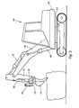
- FIGs 3, 4 and 5 illustrate the invention applied to attachments for excavators, and the same principles apply equally to loading shovels, backhoes and the like. In these Figures, similar parts are given the same reference numerals.
- an excavator 60 has a body 62 which can slew horizontally, around a vertical axis, above a drive chassis 64.
- a primary arm 66 is pivotally mounted on body 62 for vertical motion, which is controlled and driven by a hydraulic ram 68 acting between the body and the primary arm.
- a secondary arm 70 is pivotally mounted at the distal end of the primary arm for motion in a vertical plane, driven and controlled by a hydraulic ram 72 acting between the primary and secondary arms.
- a digger bucket 74 is pivotally mounted for vertical motion at the distal end of the secondary arm, driven and controlled by a hydraulic ram 80 acting between the secondary arm and the bucket to which it is connected in the conventional manner by a crowd link 76 supported by a stabiliser link 78.
- Hydraulic hammer unit 40 is welded to crowd link 76, or may be included within the link, substantially parallel to it, and accordingly always acts in a direction parallel to the link. This means that when ram 80 is being extended to crowd or advance the bucket, the hammer unit always acts in the proper direction to assist that advance. It also means that the hammer unit can be used to assist other rams: for example, to assist the articulation of the secondary arm on the primary arm, by ram 72, the bucket can be crowded until the hammer 40 is at about 90° to the pivot mounting for the secondary arm.
- the attachment on secondary arm 70 is a demolition grapple with a pivoted jaw member 82 movable by ram 80 towards and away from adjustable jaw member 84, which is braced by stay bar 86.
- Figure 4 shows more clearly the simple welded mounting 88 for the hammer unit 40 on crowd link 76.
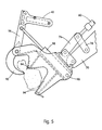
- the hammer unit 40 can be carried directly on the attachment, as shown in Figure 5.
- the attachment is a rock crusher or concrete breaker with a body 90 pivotally mounted on the distal end of secondary arm 70.
- a breaking jaw member 92 is pivotally mounted on the body in opposition to two support platforms 94 against which concrete and the like can be split or crushed by the jaw 92, when lever arm 96, which is a solid extension of the jaw, is driven by ram 98 carried by the attachment.
- Hammer mechanism 40 is carried directly on lever arm 96, at about right angles to the pivot mounting of jaw 92, so that it can act at all times in the appropriate direction to assist the advance of the jaw towards support platforms 94, under the urging of ram 98.
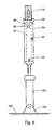
- Figure 6 shows a hydraulic jack comprising a ram 100 mounted on a pivot base 102 standing on solid ground or another support 104.
- the piston end of the ram carries a rigid round or box section tube 106 in which hammer mechanism housing 44 is rigidly mounted by the usual pins 43 in cushioned bushes.
- a workpiece-engaging tool 108 such as a cup, is welded to the top end of tube 106.
- the lower face of the tool acts as a stop for the floating anvil 46, which is again surrounded, supported and held by anvil collar 48.
- the hammer mechanism is an active component within an extension to the piston rod of the ram.
- Such an arrangement can also be used in the actuators in other embodiments of the invention.
- Figure 7 shows a hydraulic circuit in outline form suitable for the crusher of Figures 1 and 2.
- Hydraulic oil is taken from tank 120 through filter 122 by pump 124, and fed to spool valve 126.
- the feed line 128 includes an adjustable pressure relief valve 130.
- the tank is kept supplied by return oil lines (not shown) through return line filter 121.
- valve 126 In its spring biased neutral position, as shown, valve 126 returns the oil to tank.
- the valve can however be operated by lever 132, or remotely by a solenoid control, to two different working positions.
- the second working condition corresponds to the crushing operation, in which the ram 30 is used until resistance requires the hammer mechanism 40 to be brought into play.
- line 134 is connected to tank, allowing piston 136 in ram 30 to advance when sufficiently powered.
- hydraulic fluid is admitted by valve 126 to line 142, but since it cannot pass check valve 140, it flows into flow regulator 144, which has a single inlet 146, a priority outlet 148, a by-pass outlet 150, and a drain outlet 152.
- Flow regulator 144 includes a flow splitter valve 154, a normally open solenoid operated valve 156, and an adjustable relief valve 158, as well as a variable flow control valve 160.
- valves in regulator 144 are all shown in their start-up condition. Oil initially flows up to control valve 160, which causes a pressure build-up sufficient to switch the spool of valve 154 to the right. Oil then continues to flow restrictedly through valve 154 into and through variable restrictor valve 160, through further flow restrictor 162, and through solenoid valve 156 to tank via outlet 152. However, this drain flow is very small, and most of the oil exits flow regulator through by-pass outlet 150, to power crusher ram 30.
- Solenoid valve 156 can be energised manually, but also by sensing the oil pressure in line 138 rising above a threshold that corresponds to impaired progress of ram 30. In either case, the valve 156 switches to close the oil flow to outlet 152, opening instead a by-pass path around flow restrictor 162, and allowing a pressure build-up to the right of valve 154 which shifts its spool to the position shown in Figure 7.
- Relief valve 158 exists principally as a safety measure.
- the surplus flow is diverted to the by-pass outlet 150.
- the relative flows can be varied by adjusting valve 160, because the flow restriction here controls the pilot pressure to the left of valve 154.
- valve 154 shuttles back and forth, dividing the oil flow between the priority outlet to the hammer and the bypass outlet to the crusher ram, which can advance as the percussion of the hammer mechanism overcomes the resistance of the rock R ( Figure 2) in the crusher jaws.
- solenoid valve 156 can be de-energised, either manually or automatically upon sensing the advance of the ram by a suitable pressure or other transducer. The hammer then ceases operation, because the small oil flow towards the hammer through valve 154 all drains to tank through the solenoid valve.
Landscapes
- Engineering & Computer Science (AREA)
- Architecture (AREA)
- Structural Engineering (AREA)
- Mechanical Engineering (AREA)
- Civil Engineering (AREA)
- Mining & Mineral Resources (AREA)
- General Engineering & Computer Science (AREA)
- Chemical & Material Sciences (AREA)
- Chemical Kinetics & Catalysis (AREA)
- Electrochemistry (AREA)
- Working Measures On Existing Buildindgs (AREA)
- Finish Polishing, Edge Sharpening, And Grinding By Specific Grinding Devices (AREA)
- Electrical Discharge Machining, Electrochemical Machining, And Combined Machining (AREA)
- Constituent Portions Of Griding Lathes, Driving, Sensing And Control (AREA)
- Shovels (AREA)
Claims (10)
- Appareil pour effectuer un travail en avançant un outil (13, 14) à l'encontre d'une résistance (R) à celui-ci, comprenantcaractérisé en ce que l'organe porte-outil est d'une pièce avec l'outil ou au moins porte l'outil sans mouvement relatif dans la direction d'avance de l'outil, et le moyen de percussion comprend un logement (44) connecté positivement à l'organe porte-outil, une masse inertielle (45) pouvant être déplacée le long d'une trajectoire de va-et-vient à l'intérieur du logement, et des moyens (120-162) pour faire aller et venir la masse dans le logement pour augmenter de manière périodique la force persistante appliquée par l'actionneur à l'organe porte-outil et pour ainsi faciliter l'avance de l'outil par rapport à l'organe de référence à l'encontre de ladite résistance.un organe porte-outil (12);un organe de référence (22);un actionneur (30) connecté de manière fonctionnelle entre les deux organes et adapté pour appliquer et maintenir une force persistante entre eux en poussant l'organe porte-outil à avancer par rapport à l'organe de référence à l'encontre d'une dite résistance;et un moyen de percussion (40) associé à l'organe porte-outil;
- Appareil selon la revendication 1, dans lequel l'organe porte-outil (12) et l'organe de référence (22) sont interconnectés à pivotement, l'organe porte-outil pouvant être avancé à pivotement par rapport à l'organe de référence.
- Appareil selon la revendication 1 ou la revendication 2, comprenant un organe de mâchoire de concassage (12) monté à pivotement et un support de matériaux (22) opposé à celui-ci et espacé de celui-ci, des matériaux (R) pouvant être engagés par l'organe de mâchoire sur le support, et concassés sur celui-ci; et un moyen de percussion (40) associé à l'organe de mâchoire pour ainsi augmenter les forces de concassage exercées par la mâchoire pivotée sur lesdits matériaux.
- Appareil selon l'une quelconque des revendications précédentes, dans lequel l'actionneur pour faire avancer l'organe porte-outil est un actionneur hydraulique (30) utilisant un fluide hydraulique substantiellement incompressible, comprenant des moyens (140, 154, 156) pour empêcher que des impulsions vers l'arrière dues à la masse animée d'un mouvement de va-et-vient ne rétractent l'actionneur , tout en permettant à davantage de fluide d'être admis dans l'actionneur quand des impulsions vers l'avant dues à la masse animée d'un mouvement de va-et-vient font avancer l'organe porte-outil.
- Appareil selon l'une quelconque des revendications précédentes, dans lequel la masse animée d'un mouvement de va-et-vient (45) vient frapper une enclume (46) substantiellement fixe à l'extrémité d'impulsion de sa course.
- Appareil selon l'une quelconque des revendications précédentes, dans lequel l'actionneur (30) et le moyen de percussion (40) sont tous deux entraínés fluidiquement, et comportent un moyen (154) pour dévier la puissance du fluide de l'actionneur vers le moyen de percussion lorsque l'avance de l'outil à l'encontre de la résistance est relativement lente.
- Appareil selon la revendication 6, comprenant un moyen (156) réagissant à la pression de fluide dans l'actionneur (30) pour amorcer le mouvement de va-et-vient de la masse (45) dans le moyen de percussion (40).
- Accessoire d'excavation comprenant un appareil selon l'une quelconque des revendications précédentes, et un moyen pour attacher ledit appareil à un bras articulé (70) d'un excavateur (60).
- Concasseur de pierres, de béton ou de moteurs, comprenant un appareil selon l'une quelconque des revendications précédentes, dans lequel l'organe de référence est une plaque de support (22) pour l'objet (R) devant être concassé, et l'organe porte-outil est une plaque de concassage (12) pivotée ou un organe de mâchoire (82, 92) pivoté.
- Procédé pour effectuer un travail en avançant un outil (13, 14) à l'encontre d'une résistance (R) à celui-ci, comprenant l'application et le maintien d'une force persistante entre un organe porte-outil (12) et un organe de référence (22) dans un appareil selon l'une quelconque des revendications précédentes, et faisant aller et venir la masse inertielle (45) le long de la trajectoire de va-et-vient à l'intérieur du logement (44) pour augmenter de manière périodique la force persistante appliquée par l'actionneur (30) à l'organe porte-outil et pour ainsi faciliter l'avance de l'outil par rapport à l'organe de référence à l'encontre de ladite résistance.
Applications Claiming Priority (5)
| Application Number | Priority Date | Filing Date | Title |
|---|---|---|---|
| GB9508830 | 1995-05-01 | ||
| GBGB9508830.8A GB9508830D0 (en) | 1995-05-01 | 1995-05-01 | Breaking Apparatus |
| GBGB9600349.6A GB9600349D0 (en) | 1995-05-01 | 1996-01-09 | Performing work with a tool |
| GB9600349 | 1996-01-09 | ||
| PCT/GB1996/001040 WO1996035034A1 (fr) | 1995-05-01 | 1996-05-01 | Execution d'un travail a l'aide d'un outil |
Publications (2)
| Publication Number | Publication Date |
|---|---|
| EP0823955A1 EP0823955A1 (fr) | 1998-02-18 |
| EP0823955B1 true EP0823955B1 (fr) | 2000-03-01 |
Family
ID=26306957
Family Applications (1)
| Application Number | Title | Priority Date | Filing Date |
|---|---|---|---|
| EP96915081A Expired - Lifetime EP0823955B1 (fr) | 1995-05-01 | 1996-05-01 | Appareil pour executer un travail a l'aide d'un outil |
Country Status (6)
| Country | Link |
|---|---|
| EP (1) | EP0823955B1 (fr) |
| AT (1) | ATE190106T1 (fr) |
| CA (1) | CA2223087A1 (fr) |
| DE (1) | DE69606861D1 (fr) |
| GB (1) | GB9600349D0 (fr) |
| WO (1) | WO1996035034A1 (fr) |
Families Citing this family (3)
| Publication number | Priority date | Publication date | Assignee | Title |
|---|---|---|---|---|
| EP1174568B1 (fr) * | 2000-07-22 | 2002-03-27 | Günter Prof. Dr.-Ing. Klemm | Pince de démolition hydraulique |
| GB0707362D0 (en) * | 2007-04-17 | 2007-05-23 | Digbits Ltd | A crushing arrangement |
| RU176614U1 (ru) * | 2017-07-25 | 2018-01-24 | Федеральное государственное бюджетное образовательное учреждение высшего образования "Сибирский государственный автомобильно-дорожный университет (СибАДИ)" | Ковш экскаватора |
Family Cites Families (3)
| Publication number | Priority date | Publication date | Assignee | Title |
|---|---|---|---|---|
| DD262745A3 (de) * | 1987-04-22 | 1988-12-14 | Wohnungs Und Gesellschaftsbauk | Vorrichtung zum zerstoeren von betonelementen |
| NL8901542A (nl) * | 1989-06-20 | 1991-01-16 | Verachtert Beheer Bv | Inrichting voor het stukmaken van uit beton of dergelijk materiaal bestaande voorwerpen. |
| DE4036705A1 (de) * | 1990-11-17 | 1991-10-31 | Krupp Maschinentechnik | Verfahren zur unterstuetzung der zerkleinerungswirkung von abbruchwerkzeugen und zur durchfuehrung des verfahrens geeignetes abbruchwerkzeug |
-
1996
- 1996-01-09 GB GBGB9600349.6A patent/GB9600349D0/en active Pending
- 1996-05-01 DE DE69606861T patent/DE69606861D1/de not_active Expired - Lifetime
- 1996-05-01 AT AT96915081T patent/ATE190106T1/de not_active IP Right Cessation
- 1996-05-01 WO PCT/GB1996/001040 patent/WO1996035034A1/fr not_active Ceased
- 1996-05-01 EP EP96915081A patent/EP0823955B1/fr not_active Expired - Lifetime
- 1996-05-01 CA CA002223087A patent/CA2223087A1/fr not_active Abandoned
Also Published As
| Publication number | Publication date |
|---|---|
| EP0823955A1 (fr) | 1998-02-18 |
| CA2223087A1 (fr) | 1996-11-07 |
| ATE190106T1 (de) | 2000-03-15 |
| GB9600349D0 (en) | 1996-03-13 |
| WO1996035034A1 (fr) | 1996-11-07 |
| DE69606861D1 (de) | 2000-04-06 |
Similar Documents
| Publication | Publication Date | Title |
|---|---|---|
| US6058632A (en) | Tool holder with percussion member | |
| US4602821A (en) | Combined shovel and rock breaking chisel for an excavator | |
| US6517164B1 (en) | Hammer-ripper excavating system | |
| US5490740A (en) | Ground stabilized transportable drop hammer | |
| JP2011121054A (ja) | 破壊、粉砕またはリサイクルなどのための取付け可能油圧機器を起動する方法、およびこのような取付け可能油圧機器 | |
| EP3305995B1 (fr) | Système hydraulique de machine de construction | |
| EP1126088A2 (fr) | Système hydraulique amortisseur de charge inertielle | |
| EP1565623B1 (fr) | Mecanisme de verrouillage | |
| EP0823955B1 (fr) | Appareil pour executer un travail a l'aide d'un outil | |
| AU586538B2 (en) | Control system for an impact ripper | |
| KR20150063412A (ko) | 굴삭기를 위한 유압식 해머 장치 | |
| US6568615B2 (en) | Hydraulic breaker | |
| JP2001262629A (ja) | 作業機械におけるブームシリンダ制御回路 | |
| JPS6283504A (ja) | 構造物解体機の油圧回路 | |
| CN216430091U (zh) | 一种破碎液压控制系统及工程机械 | |
| JP2567442Y2 (ja) | ブレーカ付きバケットの駆動装置 | |
| US11752612B2 (en) | Dust suppression system for hammers | |
| US4666213A (en) | Rock breaker tool | |
| US20240326217A1 (en) | Hammer piston | |
| RU2826710C1 (ru) | Рыхлительное устройство для экскаватора | |
| CN224106495U (zh) | 一种三用一体清渣机 | |
| CN217399774U (zh) | 工程机械 | |
| CN117005486B (zh) | 工程机械的破碎锤液压系统及工程机械 | |
| JP2004052280A (ja) | 建設機械におけるアタッチメント装置 | |
| JP4367728B2 (ja) | 建設機械におけるブームシリンダ制御装置 |
Legal Events
| Date | Code | Title | Description |
|---|---|---|---|
| PUAI | Public reference made under article 153(3) epc to a published international application that has entered the european phase |
Free format text: ORIGINAL CODE: 0009012 |
|
| 17P | Request for examination filed |
Effective date: 19971127 |
|
| AK | Designated contracting states |
Kind code of ref document: A1 Designated state(s): AT BE CH DE ES FR GB IT LI NL SE |
|
| 17Q | First examination report despatched |
Effective date: 19980213 |
|
| GRAG | Despatch of communication of intention to grant |
Free format text: ORIGINAL CODE: EPIDOS AGRA |
|
| GRAG | Despatch of communication of intention to grant |
Free format text: ORIGINAL CODE: EPIDOS AGRA |
|
| GRAG | Despatch of communication of intention to grant |
Free format text: ORIGINAL CODE: EPIDOS AGRA |
|
| GRAH | Despatch of communication of intention to grant a patent |
Free format text: ORIGINAL CODE: EPIDOS IGRA |
|
| GRAH | Despatch of communication of intention to grant a patent |
Free format text: ORIGINAL CODE: EPIDOS IGRA |
|
| GRAA | (expected) grant |
Free format text: ORIGINAL CODE: 0009210 |
|
| AK | Designated contracting states |
Kind code of ref document: B1 Designated state(s): AT BE CH DE ES FR GB IT LI NL SE |
|
| PG25 | Lapsed in a contracting state [announced via postgrant information from national office to epo] |
Ref country code: SE Free format text: THE PATENT HAS BEEN ANNULLED BY A DECISION OF A NATIONAL AUTHORITY Effective date: 20000301 Ref country code: NL Free format text: LAPSE BECAUSE OF FAILURE TO SUBMIT A TRANSLATION OF THE DESCRIPTION OR TO PAY THE FEE WITHIN THE PRESCRIBED TIME-LIMIT Effective date: 20000301 Ref country code: LI Free format text: LAPSE BECAUSE OF NON-PAYMENT OF DUE FEES Effective date: 20000301 Ref country code: IT Free format text: LAPSE BECAUSE OF FAILURE TO SUBMIT A TRANSLATION OF THE DESCRIPTION OR TO PAY THE FEE WITHIN THE PRESCRIBED TIME-LIMIT;WARNING: LAPSES OF ITALIAN PATENTS WITH EFFECTIVE DATE BEFORE 2007 MAY HAVE OCCURRED AT ANY TIME BEFORE 2007. THE CORRECT EFFECTIVE DATE MAY BE DIFFERENT FROM THE ONE RECORDED. Effective date: 20000301 Ref country code: FR Free format text: LAPSE BECAUSE OF FAILURE TO SUBMIT A TRANSLATION OF THE DESCRIPTION OR TO PAY THE FEE WITHIN THE PRESCRIBED TIME-LIMIT Effective date: 20000301 Ref country code: ES Free format text: THE PATENT HAS BEEN ANNULLED BY A DECISION OF A NATIONAL AUTHORITY Effective date: 20000301 Ref country code: CH Free format text: LAPSE BECAUSE OF NON-PAYMENT OF DUE FEES Effective date: 20000301 Ref country code: BE Free format text: LAPSE BECAUSE OF FAILURE TO SUBMIT A TRANSLATION OF THE DESCRIPTION OR TO PAY THE FEE WITHIN THE PRESCRIBED TIME-LIMIT Effective date: 20000301 Ref country code: AT Free format text: LAPSE BECAUSE OF FAILURE TO SUBMIT A TRANSLATION OF THE DESCRIPTION OR TO PAY THE FEE WITHIN THE PRESCRIBED TIME-LIMIT Effective date: 20000301 |
|
| REF | Corresponds to: |
Ref document number: 190106 Country of ref document: AT Date of ref document: 20000315 Kind code of ref document: T |
|
| REG | Reference to a national code |
Ref country code: CH Ref legal event code: EP |
|
| REF | Corresponds to: |
Ref document number: 69606861 Country of ref document: DE Date of ref document: 20000406 |
|
| PG25 | Lapsed in a contracting state [announced via postgrant information from national office to epo] |
Ref country code: DE Free format text: LAPSE BECAUSE OF FAILURE TO SUBMIT A TRANSLATION OF THE DESCRIPTION OR TO PAY THE FEE WITHIN THE PRESCRIBED TIME-LIMIT Effective date: 20000603 |
|
| EN | Fr: translation not filed | ||
| NLV1 | Nl: lapsed or annulled due to failure to fulfill the requirements of art. 29p and 29m of the patents act | ||
| REG | Reference to a national code |
Ref country code: CH Ref legal event code: PL |
|
| PLBE | No opposition filed within time limit |
Free format text: ORIGINAL CODE: 0009261 |
|
| STAA | Information on the status of an ep patent application or granted ep patent |
Free format text: STATUS: NO OPPOSITION FILED WITHIN TIME LIMIT |
|
| 26N | No opposition filed | ||
| REG | Reference to a national code |
Ref country code: GB Ref legal event code: IF02 |
|
| PGFP | Annual fee paid to national office [announced via postgrant information from national office to epo] |
Ref country code: GB Payment date: 20020930 Year of fee payment: 7 |
|
| REG | Reference to a national code |
Ref country code: GB Ref legal event code: 732E |
|
| PG25 | Lapsed in a contracting state [announced via postgrant information from national office to epo] |
Ref country code: GB Free format text: LAPSE BECAUSE OF NON-PAYMENT OF DUE FEES Effective date: 20030501 |
|
| GBPC | Gb: european patent ceased through non-payment of renewal fee |
Effective date: 20030501 |