EP0824157B1 - Caisse de tête et procédé pour la répartition d'une suspension fibreuse dans la caisse de tête d'une machine à papier - Google Patents
Caisse de tête et procédé pour la répartition d'une suspension fibreuse dans la caisse de tête d'une machine à papier Download PDFInfo
- Publication number
- EP0824157B1 EP0824157B1 EP97112824A EP97112824A EP0824157B1 EP 0824157 B1 EP0824157 B1 EP 0824157B1 EP 97112824 A EP97112824 A EP 97112824A EP 97112824 A EP97112824 A EP 97112824A EP 0824157 B1 EP0824157 B1 EP 0824157B1
- Authority
- EP
- European Patent Office
- Prior art keywords
- metering
- fibrous suspension
- flowbox
- additives
- lines
- Prior art date
- Legal status (The legal status is an assumption and is not a legal conclusion. Google has not performed a legal analysis and makes no representation as to the accuracy of the status listed.)
- Expired - Lifetime
Links
- 239000000725 suspension Substances 0.000 title claims description 72
- 238000000034 method Methods 0.000 title claims description 22
- 238000009826 distribution Methods 0.000 title description 4
- 230000008569 process Effects 0.000 title description 2
- 239000000654 additive Substances 0.000 claims description 41
- 239000000945 filler Substances 0.000 claims description 27
- XLYOFNOQVPJJNP-UHFFFAOYSA-N water Substances O XLYOFNOQVPJJNP-UHFFFAOYSA-N 0.000 claims description 22
- 238000010790 dilution Methods 0.000 claims description 15
- 239000012895 dilution Substances 0.000 claims description 15
- 239000000126 substance Substances 0.000 claims description 10
- 230000014759 maintenance of location Effects 0.000 claims description 9
- 230000001105 regulatory effect Effects 0.000 claims description 8
- 230000008859 change Effects 0.000 claims description 7
- 239000000203 mixture Substances 0.000 claims description 5
- 229920002472 Starch Polymers 0.000 claims description 4
- 239000008107 starch Substances 0.000 claims description 4
- 235000019698 starch Nutrition 0.000 claims description 4
- 230000001276 controlling effect Effects 0.000 claims 2
- 238000007670 refining Methods 0.000 claims 2
- 239000000835 fiber Substances 0.000 description 51
- 239000000123 paper Substances 0.000 description 25
- 239000010410 layer Substances 0.000 description 16
- 230000004048 modification Effects 0.000 description 9
- 238000012986 modification Methods 0.000 description 9
- 230000008901 benefit Effects 0.000 description 7
- 230000033228 biological regulation Effects 0.000 description 7
- 238000011161 development Methods 0.000 description 6
- 239000003795 chemical substances by application Substances 0.000 description 5
- 239000000463 material Substances 0.000 description 5
- 241000446313 Lamella Species 0.000 description 3
- 238000013461 design Methods 0.000 description 3
- 238000004519 manufacturing process Methods 0.000 description 3
- 230000002093 peripheral effect Effects 0.000 description 3
- 239000002356 single layer Substances 0.000 description 3
- 230000007704 transition Effects 0.000 description 3
- 230000015572 biosynthetic process Effects 0.000 description 2
- 230000000694 effects Effects 0.000 description 2
- 238000009827 uniform distribution Methods 0.000 description 2
- 230000000996 additive effect Effects 0.000 description 1
- 230000002411 adverse Effects 0.000 description 1
- 125000000129 anionic group Chemical group 0.000 description 1
- 125000002091 cationic group Chemical group 0.000 description 1
- 238000010276 construction Methods 0.000 description 1
- 238000007865 diluting Methods 0.000 description 1
- 239000004744 fabric Substances 0.000 description 1
- 239000002657 fibrous material Substances 0.000 description 1
- 239000012530 fluid Substances 0.000 description 1
- 210000000056 organ Anatomy 0.000 description 1
- 238000004806 packaging method and process Methods 0.000 description 1
- 239000010893 paper waste Substances 0.000 description 1
- 239000004033 plastic Substances 0.000 description 1
- 230000003716 rejuvenation Effects 0.000 description 1
- 239000002344 surface layer Substances 0.000 description 1
- 229920002994 synthetic fiber Polymers 0.000 description 1
- 238000012549 training Methods 0.000 description 1
- 238000005406 washing Methods 0.000 description 1
- 239000002023 wood Substances 0.000 description 1
Images


Classifications
-
- D—TEXTILES; PAPER
- D21—PAPER-MAKING; PRODUCTION OF CELLULOSE
- D21F—PAPER-MAKING MACHINES; METHODS OF PRODUCING PAPER THEREON
- D21F1/00—Wet end of machines for making continuous webs of paper
- D21F1/02—Head boxes of Fourdrinier machines
- D21F1/022—Means for injecting material into flow within the headbox
-
- D—TEXTILES; PAPER
- D21—PAPER-MAKING; PRODUCTION OF CELLULOSE
- D21F—PAPER-MAKING MACHINES; METHODS OF PRODUCING PAPER THEREON
- D21F1/00—Wet end of machines for making continuous webs of paper
- D21F1/02—Head boxes of Fourdrinier machines
-
- D—TEXTILES; PAPER
- D21—PAPER-MAKING; PRODUCTION OF CELLULOSE
- D21F—PAPER-MAKING MACHINES; METHODS OF PRODUCING PAPER THEREON
- D21F1/00—Wet end of machines for making continuous webs of paper
- D21F1/02—Head boxes of Fourdrinier machines
- D21F1/026—Details of the turbulence section
-
- D—TEXTILES; PAPER
- D21—PAPER-MAKING; PRODUCTION OF CELLULOSE
- D21F—PAPER-MAKING MACHINES; METHODS OF PRODUCING PAPER THEREON
- D21F1/00—Wet end of machines for making continuous webs of paper
- D21F1/02—Head boxes of Fourdrinier machines
- D21F1/028—Details of the nozzle section
Definitions
- the invention relates to a method for distributing a fiber suspension in the headbox of a paper machine, at which the fiber suspension from at least one distributor a guide device is guided into a nozzle from which it exits through a gap.
- the invention further relates to a headbox for a paper machine with a distributor for distributing a fiber suspension across the machine width, via a guide device is connected to a nozzle from which the fiber suspension exits through a gap and with a metering device with dosing lines for the addition of additives.
- the headbox then comprises a guide device with a first turbulence insert in the form of a pipe distributor, the opens into a mixing chamber and a second turbulence insert in the form of a manifold that connects to the Nozzle passes over.
- multilayer headboxes were therefore often used, where the fibrous web e.g. from a middle class, from an upper layer and a lower layer is generated.
- Such multi-layer headboxes have so far been predominant used for packaging and cardboard paper production.
- In this case e.g. into the middle layer of a three-layer Inferior waste paper and brought into the Outer layers of paper stock with higher strength or whiteness in Comparison to the middle class.
- the invention is therefore based on the object of a method for the distribution of a fiber suspension in the headbox To create paper machine and a headbox, with which a targeted influencing of the paper properties even with highly filled Papers on the sheet surface or in the marginal zones is made possible in the simplest possible way, and with what additional or alternatively a targeted influencing of the printability properties with graphic papers.
- a suitable headbox is also to be created, with the benefits of optimizing paper properties in Vertical direction (z direction), especially with graphic ones Papers with a single or multi-layer design can be used.
- the pressure losses in the relevant metering lines should also be considered kept as low as possible and one as possible uniform distribution of the aggregates are made possible.
- the object of the invention is in a method according to the type mentioned solved in that at least two different levels in the vertical direction (z-direction) a fiber suspension with different additives is fed or a fiber suspension with a higher degree of grinding, with a higher proportion of filler or fine material or with less chemically digested and stronger fibers than in the middle of the sheet is fed.
- Fillers or chemicals are used as additives, in particular retention agents or starch, if appropriate also Fibrous suspensions or mixtures thereof into consideration.
- the individual additives can differ due to their chemical composition, by their concentration or their physical State or distinguish their properties.
- Besides additives that affect printability are special preferred, also substances that have mechanical properties, e.g. affect the firmness or a certain Generate shrinkage behavior, e.g. to create a bias are conceivable.
- the principles of the invention also apply to one multilayer headbox can be used advantageously can.
- the properties of the manufactured Paper particularly with regard to the production, is well printable and / or from highly filled papers to to produce papers with filler contents of at least 12%.
- a fiber suspension is seen in the edge regions in the z direction fed, the better printability properties than the suspension fed in the middle of the sheet causes. It can be fiber suspension with higher Degree of grinding and / or with a higher filler or fine substance content act. In addition, a fiber suspension can be found in the middle of the sheet be fed, which causes a higher strength, thus more chemically digested fibers or stronger fibers contains.
- the consistency the fiber suspension over the machine width i.e. in y direction controlled zone by zone, while the zone by volume flows the fiber suspension kept essentially constant become.
- This measure has the advantage that when the Amount of added additives the respective total flow, which is supplied via a metering line, kept constant and thus compensation currents in the nozzle in the transverse direction can be avoided if the amount of added additives is changed.
- the additives in the guide device, in the nozzle and / or metered in the distributor are provided.
- the properties can be influenced by the addition of different additives to particular targeted way at the required points be performed.
- the metering across the machine width in the y direction and / or in the z direction regulated by zones.
- This measure has the advantage that the metered amount of each Aggregates optimally to the desired paper quality can be coordinated.
- the object of the invention is also in a headbox solved according to the type mentioned in that in the area at least one layer of different metering lines on at least flow into two different levels in the z direction.
- the metering lines can be in the Guide device, open into the nozzle and / or into the distributor.
- the properties of the fiber suspension in the z direction achieve, for example, improved paper quality on the leaf surface even with a single layer To reach headbox.
- This measure has the advantage that e.g. anionic and cationic Retention agents in the desired manner one after the other can be added to a particularly effective binding effect of the fine and fillers to reach the fibrils.
- the guide device preferably comprises a pipe distributor or plate distributor trained turbulence generator. Turbulence generators of this type have become particularly practical proven.
- control device to regulate the volume flow of the added additives provided, preferably one in the y direction and / or separate regulation of the supply of the aggregates in the z-direction enables.
- the invention is in the metering lines one device for adding an accompanying substance provided when changing the amount of aggregate in a dosing line keeping the Total volume flow guaranteed in the metering line.
- a slat is provided at least in the nozzle.
- metering lines can be used open out over the lamella.
- the lamella itself can be used for targeted metering of aggregates can be used.
- the object of the invention is also in a headbox for a paper machine with a distributor for distributing one Fibrous suspension over the machine width, that over a Guide device is connected to a nozzle from which the Fibrous suspension exits through a gap, the Headbox seen across the machine width a plurality of Sections includes, each of which via metering lines with control organs Aggregates, especially dilution water, about a plurality of outlet openings can be mixed locally, thereby solved that a plurality of sections each have their own Dosing line is assigned, which in a plurality of Line branches is divided with the outlet openings are connected.
- At least one Dosing line the different line branches with one common regulatory body coupled.
- At least one metering line a plurality of line branches each with one Provide control body.
- the pressure drops are one after the other outlet openings provided on the line branches reduced because the line branches are not only from one side forth, but from two sides into the relevant section confluence, causing the amount of one line branch to supply outlet openings is reduced accordingly and so that the pressure loss is reduced accordingly.
- Such an embodiment is particularly preferred if the different line branches from above and from below open the section, as with a step diffuser high number of rows may be the case of the different Line branches must be supplied.
- targeted quantity control can be carried out in particular reach if the individual line branches each with their own Regulators are provided.
- the sections the additives to be mixed via the metering lines be trained, of different widths.
- This measure has the advantage that the effort of the cable routing and the standard effort for the relevant sections the necessary resolution can be adjusted across the machine width can.
- a headbox according to the invention is shown schematically in Cross section shown and designated overall by the number 10.
- the headbox 10 comprises a distributor 11, which acts as a cross-flow distributor is trained and in the direction of the material flow rejuvenated in a known manner.
- a distributor 11 which acts as a cross-flow distributor is trained and in the direction of the material flow rejuvenated in a known manner.
- a guide device 12 which has a turbulence insert comprises, which as a pipe distributor (plate distributor) known design is formed.
- the pipe distributor 13 opens in a nozzle 14, at the front end of a gap 19 for exit the fiber suspension is formed.
- the nozzle 14 can also be divided into several sections.
- each a plurality of such metering lines are across the machine width, i.e. seen in the y direction, each a plurality of such metering lines side by side arranged.
- the metering lines 20 - 22 or 23 - 25 or 26 - 28 each open at different levels in the z direction in the distributor 11 or in the pipe distributor 13 or into the nozzle 14.
- Additives are added via the metering lines 20 - 28 specific at different points of the headbox Additives are added.
- the substances added can be fillers, fibrous materials, Chemicals, especially retention agents, starch or also around fiber suspensions or mixtures of these dosing media act.
- the Dosing quantity of each individual dosing line 20 - 28 separately control can be that optionally by admixing an aqueous Aggregate, e.g. of white water, the total volume flow each individual dosing line despite a change in the quantity of the added aggregate remains constant. In this way is avoided by varying the individual volume flows Equalization flows in the z direction in the nozzle 14 arise, leading to changes in the fiber orientation cross profile would lead.
- an aqueous Aggregate e.g. of white water
- the metering lines 20 - 28 can be used to target the center of the sheet less retention aids are dosed than in the peripheral areas. Furthermore, fewer fillers can be metered into the middle of the sheet are considered to be in the fringe areas. In this way, an increased Concentration of fine and fillers on the leaf surface supported. The high fines content in the A filter auxiliary layer through the fine and fillers be held on the surface. By the lesser The amount of retention agent in the middle of the leaf becomes less Binding effect of fine and fillers in this zone which causes the fibers to transport fine and fillers to the leaf surface is supported.
- FIG. 2 A modification of the embodiment according to FIG. 1 is shown in FIG. 2 and designated overall by the number 30.
- the fiber suspension is used as a cross-flow distributor trained distributor 31 supplied and arrives from there via a guide device 32 into a nozzle 34, which exits through a gap 39.
- the leadership facility 32 comprises a first as a pipe or plate distributor 33 trained turbulence insert, to which a Mixing chamber 35 connects to the second as a pipe or Plate distributor 36 trained turbulence insert connects.
- a lamella 37 is also provided in the nozzle 34, i.e. a slab across the width of the web leading into space protrudes the nozzle 34 and attached either horizontally or inclined is or articulated on its facing the plate distributor 36 End is attached.
- a total of four metering lines 40-43 are shown in FIG. which protrude into the mixing chamber 35 and overall three metering lines 44 - 46, which are in the front part of the nozzle 34 protrude.
- the two metering lines 40, 41 are in Viewed in the direction of the current, arranged one behind the other and flow at the same level in the z direction at the top of the Mixing chamber 35.
- the two following metering lines open 42, 43 at the lower end of the mixing chamber 35 on the same level. They are also in one after the other Flow direction arranged.
- the three metering lines 44, 45, 46 open on different Levels in the z direction into the nozzle 34.
- valves 49 there are 40-46 valves 49 in all metering lines provided to meter the additives in the desired manner to be able to.
- FIG. 3 Another modification of a headbox according to the invention is shown in Fig. 3 and generally designated by the number 50.
- the fibrous suspension is in turn via an as Cross flow distributor trained distributor 51 supplied by from them via a guide device 52 in the form of a Pipe distributor 53 enters the nozzle 54, from which the fiber suspension flows out through the gap 59.
- Fig. 3 three metering lines 60-62 are shown, the at different levels in the z direction in the pipe distributor 53 flow into.
- valves 69 to 64 in the metering lines for regulation intended.
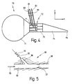
- FIG. 4 Another modification of a headbox according to the invention is shown in Fig. 4 and generally designated by the numeral 70.
- the pulp suspension is used as a cross flow distributor trained distributor 71 fed and arrives from there via the guide device 72, which acts as a pipe distributor or plate distributor 73 is formed into the nozzle 74 which flows out through a gap 79.
- the Dosing lines 80 - 82 not vertically into the pipe distributor 73 one but at an obtuse angle chosen so that even with a change in the flow of the aggregates through the metering lines 80 - 82 the respective total volume flow through the relevant pipeline of the manifold 73 is not changed.
- This measure has the advantage that regardless of the quantity of the added additives, the respective total volume flow not changed by the individual pipes of the manifold 73 is, so that despite a change in the amount of metered Aggregates in the nozzle 74 no equalizing flows arise can, so that the fiber orientation profile is not affected.
- FIG. 5 shows a mixing device for mixing two volume flows shown as used according to EP 0 565 923 A1 can be.
- the mixing device designated as a whole by the number 90 comprises a first pipe for carrying a main flow 92 in Direction of an arrow 93 into which a second pipe for guidance a side stream 96 in the direction of an arrow 95 with formation at an angle between the two pipes.
- Secondary flow 96 can be regulated via a valve 94.
- the angle between the two streams 92, 96 is selected in such a way that even with a change in volume flow of the secondary flow 96 the total volume flow through the outlet end 98 largely unchanged.
- the angle is usually in the range between about 85 ° and 87 °.
- Such mixing devices 90 are used to determine the basis weight cross-section to be able to regulate in the y direction like this is basically known from EP 0 565 923 A1 and below is explained with reference to FIG. 6.
- FIG. 6 shows a headbox according to the invention as a whole number 100.
- the headbox 100 comprises a first distributor 101 for guidance a fiber suspension with a relatively high fiber concentration and a second distributor 106 with less Diameter in which white water is preferably led.
- the second distributor 106 is via valves 107 and lines 108 each connected to a mixing device 109, which after the is constructed on the basis of FIG. 5 and in which Dilution water from the second distributor 106 in the volume flow is mixed from the first distributor 101, without this the total volume flow through the respective line 110 changes becomes.
- the mixing devices 109 are via the lines 110 connected to a subsequent guide device 102, which in turn connects to the nozzle 104.
- the leadership facility 102 in turn comprises a plate distributor Pipe distributor 103, in the metering lines 111, 112, 113 merge at different levels in the z direction to different To be able to add additives.
- the basis weight cross-section can be influenced in the desired manner without the fiber orientation cross profile is adversely changed.
- additives can be added via the metering lines 111 - 113 can be added in the desired manner to add properties in the z-direction or y-direction.
- FIG. 7 shows a further modification of an inventive one Headbox shown and generally designated by the number 120.
- a first distributor 121 serves for the main supply of the headbox 120 in the middle area except the edge zones in the y direction seen. This distributor 121 becomes a fiber suspension fed with a relatively low degree of grinding.
- Another distributor 137 is used to supply fiber suspension with a higher degree of grinding, preferably in the peripheral areas is fed.
- a third distributor 126 is used to supply white water for diluting those from the first distributor 121 or the second Distributor 137 branched fiber suspension.
- the third Distributor 126 is in turn via valves 127 and lines 128 connected to mixing devices 129, the fiber suspension is fed from the second distributor 137, or via Valves 127 and lines 131 connected to mixing devices 132, those fiber suspension from the first distributor 121 is fed.
- the mixing devices 129 and 132 are finally via lines 130 or 133 connected to the pipe distributor 123.
- aggregates can be fed through metering lines 134-136 are metered into the pipe divider 123 at different levels, to specifically influence the properties of the fibrous web 125 to achieve.
- the headbox 140 includes a first manifold 141 for receiving of high concentration pulp suspension for regulation of the consistency cross section from a secondary distributor 142 via valves 143 and lines 144 via mixer devices 145 with throttling points 146 lower fiber suspension Concentration, e.g. White water is added.
- Two more Distributors 148 and 150 are for receiving fiber suspension provided that fed into the upper and lower edge areas is targeted to the printability in the marginal areas to improve.
- the three fiber suspensions will be via lines 147, 149, 151 and guide devices 152 in Nozzles 154 guided, from which they form a column Fibrous web 155 between a lower one via a wire guide roller 156 guided screen 157 and an upper one Screen guide roller 158 guided screen 159 are imposed.
- FIG 9 shows another headbox according to the invention for a paper machine designated overall by the number 210.
- the headbox 210 comprises a cross-distributor Distributor 212, which has a guide device 214 a nozzle 218 is connected, from which the fiber suspension supplied exits through a machine-wide gap 220.
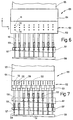
- the guide device 214 comprises a pipe distributor 16 or Step diffuser with a variety of tubes, the structure of which the sectional view of FIG. 10 can be seen in more detail.
- the headbox 210 is divided over the machine width (y direction) into a plurality of sections S 1 , S 2 , S 3 , .., as can be seen from FIG. 10.
- An aggregate is regulated for each individual section, in particular Dilution water, mixed to give a local consistency To enable regulation without the gap 220 being adjusted must become.
- Dosing lines provided with different outlet openings in manifold 212, in manifold 216 and in open the nozzle 218.
- each metering line 222, 234, 248 has a plurality of outlet openings the metering lines 222, 234, 248 divided into individual line branches in order to reduce the pressure loss to keep it smaller at the outlet openings and so one more uniform distribution of the aggregate in the z direction to ensure.
- the first metering line 222 which is in the transition area between Distributor 212 and pipe distributor 216 opens out of one common feed line 226 fed with white water and is about a common regulator that is controllable as a motor Valve can be designed, adjustable.
- the dosing line 222 is divided into two line branches 228, 230, the bottom and from above into the transition area between distributors 212 and pipe manifold 216 open and the ends of one closed loop are connected.
- the dilution water passes through several outlet openings arranged one above the other in the z direction from which three exit openings are exemplary 231, 232, 233 are shown.
- the second metering line 234 becomes a feed line 238 fed with dilution water, whose volume flow over a common regulator 236 can be regulated.
- the regulatory body 236 is the metering line 234 via a distributor 235 in three individual line branches 240, 242, 244 divided, one after the other seen in the x direction at different levels in the z direction open into the manifold 216 and from which the Dilution water emerges through outlet openings from which the outlet openings 245, 246, 247 are shown as examples are.
- the third metering line 248 is in turn made up of a common one Feed line 256 powered, but includes the metering line 248 three completely separate line branches 258, 260, 262, each with a control unit 250, 252, 254 with the feed line 256 are connected and at their lower ends open at different levels in the nozzle 218 to dilution water via outlet openings, of which the example Outlet openings 263, 264, 265 are shown on different To be able to feed in levels in the z direction.
- the pipe distributor or step diffuser consists of a large number of individual tubes, which are in the main flow direction, i.e. extend in the x direction and expand gradually in the x direction. In the z direction dosing lines are provided to dilution water to be able to mix.
- the pipe distributor is divided into individual sections S 1 , S 2 , S 3 , .., viewed in the y direction, which can be individually controlled in order to enable local consistency control over the machine width.
- a section S 1 , S 2 is supplied with dilution water by a metering line 282, 284.
- Each metering line 282, 284 is divided into two line branches 266, 268 and 286, 288, which open into the pipe distributor from above and from below.
- the line branches are again divided within the pipe distributor itself into two partial strands, which extend in the z-direction between the individual pipes 270, as is exemplified by the partial strands 274, 276, and from which dilution water via outlet openings 272 into the pipes 270 des Pipe distributor passes.
- this version is of course also special advantageous for the supply of the additives in the form of Fillers, chemicals, especially retention aids, starch, Fibrous suspensions or the like, or mixtures thereof, at different levels in the z direction for targeted influencing the paper properties can be used.
- the metering lines 258, 260, 262 the different levels in the z direction open into the nozzle 218, formed as ring lines in individual sections be fed from individual distributors.
- This version can also be used with the previously mentioned versions can be combined, i.e. only to supply dilution water used while additionally different Additives are added in the z direction.
Landscapes
- Paper (AREA)
Claims (26)
- Procédé pour la répartition d'une suspension fibreuse dans une caisse de tête d'une machine à papier, dans lequel la suspension fibreuse est conduite d'au moins un répartiteur (11, 31, 51, 71, 101, 106, 121, 126, 137, 141, 142, 148, 150) par un dispositif de guidage (12, 32, 52, 72, 102, 122, 152) dans une tuyère (14, 34, 54, 74, 104, 124, 154), de laquelle elle sort par une fente (19, 39, 59, 79), caractérisé en ce que l'on introduit une suspension fibreuse avec des matières d'addition différentes, ou une suspension fibreuse à plus haut degré de broyage, à plus haute fraction de matière de charge ou à plus haute fraction de matières fines ou avec des fibres moins désagrégées chimiquement et plus solides que dans le milieu de la feuille, à au moins deux niveaux différents en direction verticale (direction z).
- Procédé suivant la revendication 1, caractérisé en ce que l'on ajoute comme matières d'addition dosées des matières de charge, des substances chimiques, en particulier des agents de rétention, de l'amidon, une suspension fibreuse, ou des mélanges de ceux-ci.
- Procédé suivant la revendication 1 ou 2, caractérisé en ce que, vu dans la direction z, on ajoute moins d'agent de rétention dans le milieu de la feuille que dans les zones de bord de la suspension fibreuse.
- Procédé suivant l'une quelconque des revendications précédentes, caractérisé en ce que, vu dans la direction z, on ajoute moins de matières de charge et/ou de matières fines dans le milieu de la feuille que dans les régions de bord.
- Procédé suivant une ou plusieurs des revendications précédentes, caractérisé en ce que, vu dans la direction z, on ajoute dans le milieu de la feuille des matières d'addition, qui augmentent la résistance, et en ce que l'on ajoute dans les régions de bord des matières d'addition qui améliorent l'imprimabilité.
- Procédé suivant l'une quelconque des revendications précédentes, caractérisé en ce que la consistance de la suspension fibreuse est réglée par zones sur la largeur de la machine (direction y), tandis que les débits volumiques par zones de la suspension fibreuse sont maintenus sensiblement constants.
- Procédé suivant l'une quelconque des revendications précédentes, caractérisé en ce que les débits volumiques des matières d'addition ajoutées par doses sont chaque fois maintenus constants par l'ajout d'un agent d'accompagnement aqueux.
- Procédé suivant l'une quelconque des revendications précédentes, caractérisé en ce que les matières d'addition dosées sont ajoutées dans le dispositif de guidage (12, 32, 52, 72, 102, 122, 152), dans la tuyère (14, 34, 54, 154) et/ou dans le répartiteur (11, 141, 148, 150).
- Procédé suivant l'une quelconque des revendications précédentes, caractérisé en ce que l'addition dosée est réglée sur la largeur de la machine en direction horizontale (direction y) et/ou par zones dans la direction z.
- Procédé suivant l'une quelconque des revendications précédentes, caractérisé en ce qu'une modification du grammage provoquée par l'addition dosée de matières d'addition sur la largeur de la machine (direction y) est compensée par une régulation du flux de matières venant du répartiteur (101, 121, 137, 141) et d'une suspension fibreuse ajoutée avec une autre concentration.
- Procédé suivant l'une quelconque des revendications précédentes pour la répartition d'une suspension fibreuse dans une caisse de tête à plusieurs couches d'une machine à papier, dans lequel la suspension fibreuse est conduite d'au moins deux répartiteurs (11, 31, 51, 71, 101, 106, 121, 126, 137, 141, 142, 148, 150) par des dispositifs de guidage (12, 32, 52, 72, 102, 122, 152) dans des tuyères (14, 34, 54, 74, 104, 124, 154), desquelles elle sort par des fentes (19, 39, 59, 79), caractérisé en ce que, vu dans la direction z, on introduit dans les régions de bord une suspension fibreuse à plus haut degré de broyage, à plus haute fraction de matière de charge ou à plus haute fraction de matières fines ou avec des fibres moins désagrégées chimiquement et plus solides que dans le milieu de la feuille.
- Procédé suivant la revendication 11, caractérisé en ce que, vu sur la largeur de la machine dans la direction y, on introduit dans les régions de bord une suspension fibreuse ayant d'autres propriétés que dans le milieu de la feuille.
- Procédé suivant l'une quelconque des revendications précédentes, caractérisé en ce que, vu dans la direction y, on ajoute à la suspension fibreuse, au milieu de la feuille, des matières d'addition dosées en d'autres quantités ou avec d'autres propriétés que dans les régions de bord.
- Caisse de tête pour une machine à papier avec un répartiteur (11, 31, 51, 71, 101, 106, 121, 126, 137, 141, 142, 148, 150) pour la répartition d'une suspension fibreuse sur la largeur de la machine, qui est relié par un dispositif de guidage (12, 32, 52, 72, 102, 122, 152) à une tuyère (14, 34, 54, 74, 104, 124, 154), de laquelle la suspension fibreuse sort par une fente (19, 39, 59, 79), et avec un dispositif d'addition dosée avec des conduites de dosage (20-28, 40-46, 60-64, 80-82, 111-113, 134-136) pour l'addition dosée de matières d'addition, caractérisée en ce que plusieurs conduites de dosage débouchent à au moins deux niveaux différents en direction verticale (direction z).
- Caisse de tête suivant la revendication 14, caractérisée en ce que les conduites de dosage (20-28, 40-46, 60-64, 80-82, 111-113, 134-136) débouchent dans le dispositif de guidage (12, 32, 52, 72, 102, 122), dans la tuyère (14, 34, 54, 74, 104, 124) et/ou dans le répartiteur (11, 31, 51, 71, 101, 106, 121, 126, 137).
- Caisse de tête suivant la revendication 15, caractérisée en ce que, vu vers l'aval dans la direction principale d'écoulement (direction x), plusieurs conduites de dosage (40, 41, 42, 43) sont disposées l'une derrière l'autre.
- Caisse de tête suivant l'une des revendications 14 à 16, caractérisée en ce qu'il est prévu un dispositif de régulation (18) pour la régulation du débit volumique des matières d'addition dosées, qui permet de préférence une régulation de l'alimentation des matières d'addition séparément dans la direction y et/ou dans la direction z.
- Caisse de tête suivant une ou plusieurs des revendications 14 à 17, caractérisée en ce qu'il est prévu au moins une lamelle (37, 57, 58) dans la tuyère (34, 35), et en ce qu'au moins quelques-unes des conduites de dosage (63, 64) débouchent au-dessus de la lamelle (57, 58).
- Caisse de tête pour une machine à papier avec un répartiteur (212) pour la répartition d'une suspension fibreuse sur la largeur de la machine, qui est relié par un dispositif de guidage (214) à une tuyère (218), de laquelle la suspension fibreuse sort par une fente (220), dans laquelle la caisse de tête comprend, vu suivant la largeur de la machine (direction y), une pluralité de sections (S1, S2, S3) auxquelles, chaque fois par des conduites de dosage (222, 234, 248, 282, 284) avec des organes de régulation (224, 236, 250, 252, 254), des matières d'addition, en particulier de l'eau de dilution, peuvent être mélangées localement par une pluralité d'orifices de sortie (231, 232, 233, 245, 246; 247, 263, 264, 265, 272), suivant l'une des revendications 14 à 18, caractérisée en ce qu'à une pluralité de sections (S1, S2, S3) est chaque fois associée une conduite de dosage propre (222, 234, 248, 282, 284), qui est subdivisée en une pluralité de conduites ramifiées (228, 230, 240, 242, 244, 258, 260, 262, 266, 268, 286, 288), qui sont raccordées aux orifices de sortie (231, 232, 233, 245, 246, 247, 263, 264, 265, 272).
- Caisse de tête suivant la revendication 19, caractérisée en ce que, pour au moins une conduite de dosage (222, 234), les différentes conduites ramifiées (228, 230, 240, 242, 244) sont couplées à un organe de régulation commun (224, 236).
- Caisse de tête suivant la revendication 19 ou 20, caractérisée en ce que, pour au moins une conduite de dosage (222, 282, 284), les différentes conduites ramifiées (228, 230, 266, 268, 286, 288) débouchent par les côtés opposés dans la section (S1, S2, S3).
- Caisse de tête suivant la revendication 21, caractérisée en ce que, pour au moins une conduite de dosage (222, 282, 284), les différentes conduites ramifiées (228, 230, 266, 268, 286, 288) débouchent par le haut et par le bas dans la section (S1, S2, S3).
- Caisse de tête suivant l'une quelconque des revendications 14 à 22, caractérisée en ce que, pour au moins une conduite de dosage, les différentes conduites ramifiées débouchent, vu dans la direction y, l'une à côté de l'autre dans la section.
- Caisse de tête suivant l'une quelconque des revendications 14 à 23, caractérisée en ce que, pour au moins une conduite de dosage (234, 248), les différentes conduites ramifiées (240, 242, 244) débouchent, vu dans la direction principale d'écoulement (direction x), l'une derrière l'autre dans la section (S1, S2, S3).
- Caisse de tête suivant l'une quelconque des revendications 14 à 24, caractérisée en ce que, pour au moins une conduite de dosage (248), une pluralité de conduites ramifiées (258, 260, 262) sont chacune pourvues d'un organe de régulation (250, 252, 254).
- Caisse de tête suivant l'une quelconque des revendications 14 à 25, caractérisée en ce que les sections sont de largeurs différentes.
Applications Claiming Priority (4)
| Application Number | Priority Date | Filing Date | Title |
|---|---|---|---|
| DE1996132672 DE19632672A1 (de) | 1996-08-14 | 1996-08-14 | Stoffauflauf und Verfahren zum Verteilen einer Faserstoffsuspension im Stoffauflauf einer Papiermaschine |
| DE1996132673 DE19632673A1 (de) | 1996-08-14 | 1996-08-14 | Stoffauflauf und Verfahren zur Verteilung einer Faserstoffsuspension im Stoffauflauf einer Papiermaschine |
| DE19632673 | 1996-08-14 | ||
| DE19632672 | 1996-08-14 |
Publications (3)
| Publication Number | Publication Date |
|---|---|
| EP0824157A2 EP0824157A2 (fr) | 1998-02-18 |
| EP0824157A3 EP0824157A3 (fr) | 1998-04-01 |
| EP0824157B1 true EP0824157B1 (fr) | 2001-12-05 |
Family
ID=26028381
Family Applications (1)
| Application Number | Title | Priority Date | Filing Date |
|---|---|---|---|
| EP97112824A Expired - Lifetime EP0824157B1 (fr) | 1996-08-14 | 1997-07-25 | Caisse de tête et procédé pour la répartition d'une suspension fibreuse dans la caisse de tête d'une machine à papier |
Country Status (2)
| Country | Link |
|---|---|
| EP (1) | EP0824157B1 (fr) |
| DE (1) | DE59705631D1 (fr) |
Cited By (4)
| Publication number | Priority date | Publication date | Assignee | Title |
|---|---|---|---|---|
| JP2000096474A (ja) * | 1998-09-24 | 2000-04-04 | Voith Sulzer Papiertechnik Patent Gmbh | 繊維ウェブの濃度断面プロフィルを改善するための方法および流送箱システム |
| DE102008041954A1 (de) | 2008-09-10 | 2010-03-11 | Voith Patent Gmbh | Verfahren und Vorrichtung zur Herstellung einer Faser- oder Vliesstoffbahn |
| DE102008054634A1 (de) | 2008-12-15 | 2010-06-17 | Voith Patent Gmbh | Formiereinheit, insbesondere Hochkonsistenz-Blattbildungseinheit, Verwendung und Verfahren zur Steuerung der Betriebsweise einer derartigen Formiereinheit |
| WO2026027538A1 (fr) * | 2024-07-30 | 2026-02-05 | Andritz Küsters Gmbh | Système de production d'une bande fibreuse déposée par voie humide à largeur régulée, procédé de production d'une bande fibreuse déposée par voie humide à largeur régulée |
Families Citing this family (20)
| Publication number | Priority date | Publication date | Assignee | Title |
|---|---|---|---|---|
| US6117272A (en) * | 1998-09-03 | 2000-09-12 | Voith Sulzer Papiermaschinen | Device and process for metering auxiliary materials into the flow box of a paper machine |
| DE19906062A1 (de) * | 1999-02-12 | 2000-08-17 | Voith Sulzer Papiertech Patent | Verfahren und Vorrichtung zur Herstellung einer Materialbahn |
| FI113672B (fi) | 1999-04-28 | 2004-05-31 | Metso Paper Inc | Menetelmä ja laitteisto laimennusnesteen sekoittamiseksi massavirtaukseen paperikoneessa tai kartonkikoneessa |
| FI105118B (fi) | 1999-05-12 | 2000-06-15 | Valmet Corp | Menetelmä paperi- tai kartonkirainan valmistamiseksi ja paperi- tai kartonkikone |
| FI991096A7 (fi) * | 1999-05-12 | 2000-11-13 | Valmet Corp | Menetelmä paperin, erityisesti hienopaperin, valmistamiseksi ja paperi konelinja erityisesti hienopaperin valmistamista varten |
| WO2002025013A1 (fr) | 2000-09-20 | 2002-03-28 | Akzo Nobel N.V. | Procede de production de papier |
| AUPR623101A0 (en) * | 2001-07-09 | 2001-08-02 | Amcor Packaging (Australia) Pty Ltd | Apparatus and method for improving paper strength |
| US6821387B2 (en) | 2001-12-19 | 2004-11-23 | Paper Technology Foundation, Inc. | Use of fractionated fiber furnishes in the manufacture of tissue products, and products produced thereby |
| US20030111195A1 (en) | 2001-12-19 | 2003-06-19 | Kimberly-Clark Worldwide, Inc. | Method and system for manufacturing tissue products, and products produced thereby |
| US6797114B2 (en) | 2001-12-19 | 2004-09-28 | Kimberly-Clark Worldwide, Inc. | Tissue products |
| DE10245154A1 (de) * | 2002-09-27 | 2004-04-15 | Voith Paper Patent Gmbh | Stoffauflauf |
| FI122074B (fi) | 2002-10-24 | 2011-08-15 | M Real Oyj | Menetelmä kuitutuotteen valmistamiseksi |
| DE10333524A1 (de) * | 2003-07-23 | 2005-02-17 | Voith Paper Patent Gmbh | Verfahren und Vorrichtung zur Herstellung einer Faserstoffbahn, insbesondere SC-A- oder SC-B-Papierbahn |
| DE10351295A1 (de) * | 2003-10-31 | 2005-06-02 | Voith Paper Patent Gmbh | Verfahren zum Erzeugen einer Faserstoffbahn und Vorrichtung zur Durchfühung des Verfahrens |
| DE102004055919A1 (de) * | 2004-11-19 | 2006-05-24 | Voith Paper Patent Gmbh | Stoffauflauf |
| DE102008054896A1 (de) | 2008-12-18 | 2010-07-01 | Voith Patent Gmbh | Stoffauflauf für eine Maschine zur Herstellung einer Faserstoffbahn |
| DE102008054897A1 (de) | 2008-12-18 | 2010-07-01 | Voith Patent Gmbh | Stoffauflauf für eine Maschine zur Herstellung einer Faserstoffbahn |
| DE102008054898A1 (de) | 2008-12-18 | 2010-06-24 | Voith Patent Gmbh | Stoffauflauf für eine Maschine zur Herstellung einer Faserstoffbahn |
| DE102010001613A1 (de) * | 2010-02-05 | 2011-08-11 | Voith Patent GmbH, 89522 | Stoffauflauf und Blattbildungseinheit mit einem Stoffauflauf |
| CN103276618A (zh) * | 2013-05-30 | 2013-09-04 | 华南理工大学 | 一种造纸化学品的添加装置 |
Family Cites Families (3)
| Publication number | Priority date | Publication date | Assignee | Title |
|---|---|---|---|---|
| DE3514554C3 (de) * | 1984-09-19 | 1998-01-08 | Escher Wyss Gmbh | Stoffauflauf-Vorrichtung für eine Papiermaschine und Verfahren zu deren Betrieb |
| DE4416898C2 (de) * | 1994-05-13 | 1996-03-28 | Voith Sulzer Papiermasch Gmbh | Stoffauflauf für eine Papiermaschine mit lokaler Zumischung von Fluid |
| DE4423695C2 (de) * | 1994-07-06 | 1996-10-31 | Voith Sulzer Papiermasch Gmbh | Verfahren zur Herstellung einer Papier- oder Kartonbahn |
-
1997
- 1997-07-25 DE DE59705631T patent/DE59705631D1/de not_active Expired - Lifetime
- 1997-07-25 EP EP97112824A patent/EP0824157B1/fr not_active Expired - Lifetime
Cited By (4)
| Publication number | Priority date | Publication date | Assignee | Title |
|---|---|---|---|---|
| JP2000096474A (ja) * | 1998-09-24 | 2000-04-04 | Voith Sulzer Papiertechnik Patent Gmbh | 繊維ウェブの濃度断面プロフィルを改善するための方法および流送箱システム |
| DE102008041954A1 (de) | 2008-09-10 | 2010-03-11 | Voith Patent Gmbh | Verfahren und Vorrichtung zur Herstellung einer Faser- oder Vliesstoffbahn |
| DE102008054634A1 (de) | 2008-12-15 | 2010-06-17 | Voith Patent Gmbh | Formiereinheit, insbesondere Hochkonsistenz-Blattbildungseinheit, Verwendung und Verfahren zur Steuerung der Betriebsweise einer derartigen Formiereinheit |
| WO2026027538A1 (fr) * | 2024-07-30 | 2026-02-05 | Andritz Küsters Gmbh | Système de production d'une bande fibreuse déposée par voie humide à largeur régulée, procédé de production d'une bande fibreuse déposée par voie humide à largeur régulée |
Also Published As
| Publication number | Publication date |
|---|---|
| EP0824157A2 (fr) | 1998-02-18 |
| DE59705631D1 (de) | 2002-01-17 |
| EP0824157A3 (fr) | 1998-04-01 |
Similar Documents
| Publication | Publication Date | Title |
|---|---|---|
| EP0824157B1 (fr) | Caisse de tête et procédé pour la répartition d'une suspension fibreuse dans la caisse de tête d'une machine à papier | |
| DE3741603C2 (fr) | ||
| EP0785305B1 (fr) | Procédé de commande d'une caisse de tête d'une machine à papier | |
| DE4005281C2 (de) | Stoffauflauf mit Regelung des Flächengewicht-Querprofiles über die Verdünnung der Fasersuspension | |
| DE69913450T2 (de) | Stoffauflauf zur Verteilung von Faserstoffsuspension und Zusatzstoffe | |
| DE1907213A1 (de) | Verfahren und Vorrichtung zur Beaufschlagung des Formsiebes einer Papiermaschine mit Faserstoffsuspension | |
| DE2857473A1 (de) | Mikroturbulenz erzeuger fuer den stoffauflaufkasten einer papiermaschine | |
| EP0995834B1 (fr) | Procédé et dispositif pour améliorer le profil transversal du rétrécissement dans une machine à papier | |
| DE4416909C2 (de) | Stoffauflauf für eine Papiermaschine | |
| WO2010069651A1 (fr) | Caisson de tête pour machine de fabrication d'une bande de matière fibreuse | |
| EP0992625B1 (fr) | Système de caisse de tête et procédé pour l'amélioration du profil transversal de la consistence d'une bande fibreuse | |
| DE9115296U1 (de) | Stoffauflauf | |
| DE19632673A1 (de) | Stoffauflauf und Verfahren zur Verteilung einer Faserstoffsuspension im Stoffauflauf einer Papiermaschine | |
| EP0570733B1 (fr) | Dispositif d'enduction pour déposer une couleur d'enduction sur une bande de papier | |
| DE102004035303A1 (de) | Stoffauflauf für eine Maschine zur Herstellung einer Faserstoffbahn, insbesondere einer Papier- oder Kartonbahn | |
| AT507115A2 (de) | Verfahren und system zur optimierung von eigenschaften einer faserbahn | |
| DE4140657C2 (de) | Stoffauflauf | |
| DE4423695A1 (de) | Verfahren zur Herstellung einer Papier- oder Kartonbahn | |
| DE9212448U1 (de) | Doppelsiebformer mit örtlich verstellbarer Entwässerungsleiste | |
| EP2531647B1 (fr) | Caisse de tête et unité de formation de feuille comprenant une caisse de tête | |
| EP1028191A2 (fr) | Procédé et dispositif pour la production d'une bande | |
| EP0989230B1 (fr) | Procédé et dispositif pour tenir propre ou pour nettoyer le conduit de la faible consistance d'un système de caisse de tête | |
| DE102018120162A1 (de) | Stoffauflauf | |
| DE102005000011A1 (de) | Stoffauflauf für eine Maschine zur Herstellung einer Faserstoffbahn und Verfahren zur Herstellung einer Faserstoffbahn | |
| EP0708201A1 (fr) | Caisse de tête d'une machine à papier |
Legal Events
| Date | Code | Title | Description |
|---|---|---|---|
| PUAI | Public reference made under article 153(3) epc to a published international application that has entered the european phase |
Free format text: ORIGINAL CODE: 0009012 |
|
| PUAL | Search report despatched |
Free format text: ORIGINAL CODE: 0009013 |
|
| AK | Designated contracting states |
Kind code of ref document: A2 Designated state(s): DE FI SE |
|
| AK | Designated contracting states |
Kind code of ref document: A3 Designated state(s): AT BE CH DE DK ES FI FR GB GR IE IT LI LU MC NL PT SE |
|
| 17P | Request for examination filed |
Effective date: 19980424 |
|
| RIN1 | Information on inventor provided before grant (corrected) |
Inventor name: BEGEMANN, ULRICH Inventor name: LEHLEITER, KLAUS Inventor name: LOSER, HANS Inventor name: RUF, WOLFGANG |
|
| AKX | Designation fees paid |
Free format text: DE FI SE |
|
| RBV | Designated contracting states (corrected) |
Designated state(s): DE FI SE |
|
| RAP1 | Party data changed (applicant data changed or rights of an application transferred) |
Owner name: VOITH SULZER PAPIERTECHNIK PATENT GMBH |
|
| 17Q | First examination report despatched |
Effective date: 20000112 |
|
| RAP1 | Party data changed (applicant data changed or rights of an application transferred) |
Owner name: VOITH PAPER PATENT GMBH |
|
| GRAG | Despatch of communication of intention to grant |
Free format text: ORIGINAL CODE: EPIDOS AGRA |
|
| GRAG | Despatch of communication of intention to grant |
Free format text: ORIGINAL CODE: EPIDOS AGRA |
|
| GRAH | Despatch of communication of intention to grant a patent |
Free format text: ORIGINAL CODE: EPIDOS IGRA |
|
| GRAH | Despatch of communication of intention to grant a patent |
Free format text: ORIGINAL CODE: EPIDOS IGRA |
|
| GRAH | Despatch of communication of intention to grant a patent |
Free format text: ORIGINAL CODE: EPIDOS IGRA |
|
| GRAA | (expected) grant |
Free format text: ORIGINAL CODE: 0009210 |
|
| AK | Designated contracting states |
Kind code of ref document: B1 Designated state(s): DE FI SE |
|
| REF | Corresponds to: |
Ref document number: 59705631 Country of ref document: DE Date of ref document: 20020117 |
|
| PG25 | Lapsed in a contracting state [announced via postgrant information from national office to epo] |
Ref country code: SE Free format text: LAPSE BECAUSE OF FAILURE TO SUBMIT A TRANSLATION OF THE DESCRIPTION OR TO PAY THE FEE WITHIN THE PRESCRIBED TIME-LIMIT Effective date: 20020305 |
|
| PLBE | No opposition filed within time limit |
Free format text: ORIGINAL CODE: 0009261 |
|
| STAA | Information on the status of an ep patent application or granted ep patent |
Free format text: STATUS: NO OPPOSITION FILED WITHIN TIME LIMIT |
|
| 26N | No opposition filed | ||
| PGFP | Annual fee paid to national office [announced via postgrant information from national office to epo] |
Ref country code: FI Payment date: 20110714 Year of fee payment: 15 Ref country code: DE Payment date: 20110722 Year of fee payment: 15 |
|
| PG25 | Lapsed in a contracting state [announced via postgrant information from national office to epo] |
Ref country code: DE Free format text: LAPSE BECAUSE OF NON-PAYMENT OF DUE FEES Effective date: 20130201 Ref country code: FI Free format text: LAPSE BECAUSE OF NON-PAYMENT OF DUE FEES Effective date: 20120725 |
|
| REG | Reference to a national code |
Ref country code: DE Ref legal event code: R119 Ref document number: 59705631 Country of ref document: DE Effective date: 20130201 |