EP0824734B1 - Vorrichtung zur prüfung von blattgut, wie z.b. banknoten - Google Patents
Vorrichtung zur prüfung von blattgut, wie z.b. banknoten Download PDFInfo
- Publication number
- EP0824734B1 EP0824734B1 EP96914189A EP96914189A EP0824734B1 EP 0824734 B1 EP0824734 B1 EP 0824734B1 EP 96914189 A EP96914189 A EP 96914189A EP 96914189 A EP96914189 A EP 96914189A EP 0824734 B1 EP0824734 B1 EP 0824734B1
- Authority
- EP
- European Patent Office
- Prior art keywords
- base plate
- sensor
- sensors
- gap
- component
- Prior art date
- Legal status (The legal status is an assumption and is not a legal conclusion. Google has not performed a legal analysis and makes no representation as to the accuracy of the status listed.)
- Expired - Lifetime
Links
Images



Classifications
-
- G—PHYSICS
- G07—CHECKING-DEVICES
- G07D—HANDLING OF COINS OR VALUABLE PAPERS, e.g. TESTING, SORTING BY DENOMINATIONS, COUNTING, DISPENSING, CHANGING OR DEPOSITING
- G07D7/00—Testing specially adapted to determine the identity or genuineness of valuable papers or for segregating those which are unacceptable, e.g. banknotes that are alien to a currency
Definitions
- the invention relates to a device for testing Sheets such as B. banknotes.
- Such a device is from DE-PS 32 42 789 known. It has several sensors, each of which is made up of there are two components. The two components are on opposite sides of a transport route arranged, which transports the sheet material through the sensors. The components of the sensors on one side the transport route are grouped together and attached to a separate mounting plate.
- the mounting plate rotatably mounted and can be moved from the level of the base plate be unscrewed. This rotation turns the through the component of a sensor and the transport route formed gap opened and that of the transport route facing front of the sensor components as well as the Transport route itself exposed. The elimination a banknote jam or cleaning the front the sensor components is thus possible in a simple manner.
- a disadvantage of the device is that the sensors for effective use of a mounting plate be arranged on one axis and parallel to each other have to. This leads to a larger number of sensors to an elongated device with large Space requirements. Furthermore, the housing of each Sensor components should be of the same type as possible. At Housings of different sizes must have the mounting plate each be adapted to the largest housing, which in turn requires a relatively large amount of space. To the Sensor components against removal by unauthorized persons secure, they must each have an alarm loop be provided.
- the object of the invention is propose a device for testing sheet material, where the through the sensor components and the gap formed by the transport route can be opened can and at the same time a space-saving arrangement of the Sensors and a fuse of the sensor components guaranteed against removal by unauthorized persons becomes.
- the basic idea of the invention is essentially in it, which consist of one or more components Sensors as separate units on one and / or both sides to the transport route on the front of the Attach the base plate.
- the first are used for fastening Fasteners from the back of the base plate can be operated and removed when removed allow the sensor.
- these sensor components have second Fasteners on the front of the Base plate are operable and in the released state just a movement of the sensor component relative to Allow transport system. Removing the sensor is in the released state of the second fastener not possible.
- An advantage of the device is that due to the mounting of the sensors as separate units the base plate does not specify the position of the sensors to each other, still for the design of the sensor housing consists.
- the sensors can thus on the base plate be arranged as space-saving as possible.
- the immobile Components of the sensors for example Screws fixed only from the back of the Base plate can be solved.
- the movable sensor components are the first Fastening a locking lever that is about an axis is rotatable.
- the locking lever is replaced by a corresponding one Gap inserted in the base plate and so around the axis rotated so that it is essentially in one direction is perpendicular to the gap.
- the locking lever is pushed towards the base plate, so that the movable sensor component is held securely becomes.
- the second fastener of the movable sensor component consists essentially of a seesaw that be determined or released by means of a closure can.
- the rocker is between the locking lever of the first fastener and the back of the base plate arranged.
- rocker If the rocker is by means of the front of the Base plate accessible lock released, arises a gap between the rocker and the locking lever and the sensor can be in the direction of the gap on the base plate be moved.
- the electrical connections of the movable sensor component can be arranged that when moving the moving sensor component remain.
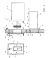
- Fig. 1 shows the schematic diagram of an inventive Contraption. It shows a sensor that consists of a movable sensor component 10 and a fixed sensor component 20 exists.
- the sensor components 10 and 20 are on opposite sides of a transport system 50 arranged, which for transporting the test item Leaf crop serves.
- the sensor is on the front V a base plate 30 attached.
- the base plate 30 is Part of a closed housing 35 and arranged so that the back R of the base plate 30 into the interior I of the closed housing 35 points.
- the fixed sensor component 20 has a rear wall 21 with an adjustment pin 22. This is in a corresponding Groove of the base plate 30 inserted so that a correct adjustment of the fixed sensor component 20 is guaranteed.
- the first fastener for the solid sensor component 20 can be, for example Screw 23 used from the back through the base plate 30 into the rear wall 21 of the sensor is screwed. This measure ensures that only the people are able to do the fixed To remove sensor component 20 from base plate 30, the access to the rear R of the base plate 30 or Have interior I of the housing 35.
- the movable sensor component 10 also has one Rear wall 11 with an adjusting pin 12.
- the adjusting pin 12 is in a corresponding groove of the base plate 30 introduced so that a correct adjustment of the movable sensor component 10 is guaranteed.
- Gap between the movable sensor component 10 and the transport system 50 is in this position with "closed gap" called.
- the movable sensor component 10 has an axis 14 on, which is connected to the rear wall 11.
- the axis 14 passes through a gap 34 of the base plate 30 and protrudes beyond the back R of the base plate 30.
- a locking lever 13 At the free end of the axis 14 is a locking lever 13 rotatably mounted.
- the closing lever 13 For fastening the movable sensor component 10 the closing lever 13 in a locking position brought, which is substantially perpendicular to the gap 34th runs.
- the locking lever 13 is by means of a suspension pressed towards the base plate 30 so that the movable sensor component 10 when closed Locking lever 13 sits firmly on the base plate 30.
- the locking lever 13 To remove the movable sensor component 10 the locking lever 13 from the rear R of the base plate 30 in an opening position substantially parallel to Gap 34 rotated.
- the shape of the locking lever 13 is so chosen that this in the open position by the Gap 34 guided and thus the movable sensor component 10 can be removed.
- a removal of the movable sensor component 10 from the base plate 30 is therefore only possible if access to the rear R the base plate 30 is guaranteed.
- a provided second fastener which consists of a Rocker 40 and a closure 42 is made.
- the closure 42 can be operated from the front V of the base plate 30 and fixes the seesaw when closed 40. In the open state, the rocker 40 is movable.
- the rocker 40 is between the locking lever 13 of the first Fasteners and the back R of the base plate 30 arranged so that it is the base for the locking lever 13 forms. Is the shutter 42 closed and thus the rocker 40 locked, pushes it against the Locking lever 13 so that the movable sensor component 10 is fixed in position. With the shutter open 42, the rocker 40 is movable and the pressure disappears against the locking lever 13. The moveable Sensor component 10 is now loosened and can be moved along of the gap 34 are moved up and down. A removal the movable sensor component 10 is not possible since the locking lever 13 in its closed Position does not lead through the gap 34.
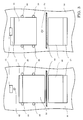
- the base plate 30 shows the base plate 30 with an example Arrangement of sensors 1 - 8 on the transport route 50.
- a suitable arrangement of the sensors 1 - 8 on the transport route 50 can take up space the device can be kept low.
- the design the housing of the sensors is practically not subject to any Limitations.
- the sensors can have components either on one side or on both sides the transport route 50 are attached. What sensor components movable and which are designed to be fixed, depends on the boundary conditions of the sensor. This Boundary conditions can include ease of maintenance, Susceptibility to repairs, frequency of jams etc.
- Fig. 3 shows a schematic diagram of the front view of a Sensors.
- the gap is closed, it is from the front of the base plate 30 accessible closure 42nd closed. If the closure 42 is opened, then the movable sensor component 10 along the here Move the invisible gap 43 upwards until the base plate 11 hits the stop 31. The gap between the transport system 50 and the movable sensor component 10 will be more open in this position Gap ".
- guides on the side 35 attached are guides on the side 35 attached. When the gap is open, the groove is 32 in the base plate 30 can be seen, in which the adjusting pin 12th penetrates with the gap closed.
- the seesaw is present 40 from a rectangular plate on two rocker bearings 41 is stored.
- the closure 42 is through the Rocker 40 passed through.
- a gap 43 In the rocker 40 is a gap 43, the dimensions of which essentially match that Gap 34 in the base plate 30 match.
- Fig. 4 shows how the adjusting pin 12 and 22 in the grooves 32 and 33 of the base plate provided for this purpose 30 intervene.
- the locking lever 13 is in the Locking position and the rocker 40 is by means of Closure 42 found.
- the pressure of the locking lever 13 on the rocker 40 serving as a base realized here by a leaf suspension 15.
- FIG. 5 shows a corresponding section open gap.
- the shutter 42 is open, and the Rocker 40 can be moved.
- the suspension 15 is now no longer able to push the locking lever 13 against the To press rocker 40. This will make the moving sensor component 10 free, so that the adjustment pin 12 from the Groove 32 pulled and the movable sensor component 10 in Direction of the gap can be moved.
- the dimensions of the gap 34 of the adjustment pin 12 and the stop 31 chosen so that the movable Sensor component 10 with the gap open through the Adjustment pin 12 and the stop 31 held securely becomes.
- the movable sensor component 10 is removed not possible because the locking lever 13 is still in the closed position. A twisting of the moved sensor component 10 can by a corresponding Choice of the dimensions of the base plate 11 of the Stop 31 of the gap 34, etc. can be prevented.
- the guides 35 which are not visible here, act a rotation of the movable sensor components 10 opposite.
- FIG. 6 shows the removal of the movable sensor component 10 shown.
- the locking lever 13 is in the Opening position rotated and can now through the gap 43rd and the gap 34 are moved so that the movable Sensor component 10 are removed from the base plate 30 can.
- each sensor component has a first fastener on just from the back the base plate 30 is operable and solved Condition allows removal of the sensor. Since the Base plate 30 is located in a housing 35 and there is arranged that its back in the interior of the Housing 35 has, now only the interior of the Housing 35 are protected against unauthorized access.
- B. seals or electrical fuses such as B. alarm loops, be secured so that the removal of such Sensor component registered by authorized persons becomes.
Landscapes
- Physics & Mathematics (AREA)
- General Physics & Mathematics (AREA)
- Inspection Of Paper Currency And Valuable Securities (AREA)
- Controlling Sheets Or Webs (AREA)
- Geophysics And Detection Of Objects (AREA)
- Burglar Alarm Systems (AREA)
- Investigating Strength Of Materials By Application Of Mechanical Stress (AREA)
Applications Claiming Priority (3)
| Application Number | Priority Date | Filing Date | Title |
|---|---|---|---|
| DE19517294 | 1995-05-11 | ||
| DE19517294A DE19517294A1 (de) | 1995-05-11 | 1995-05-11 | Vorrichtung zur Prüfung von Blattgut, wie z.B. Banknoten |
| PCT/EP1996/001965 WO1996036020A1 (de) | 1995-05-11 | 1996-05-09 | Vorrichtung zur prüfung von blattgut, wie z.b. banknoten |
Publications (2)
| Publication Number | Publication Date |
|---|---|
| EP0824734A1 EP0824734A1 (de) | 1998-02-25 |
| EP0824734B1 true EP0824734B1 (de) | 1999-09-08 |
Family
ID=7761660
Family Applications (1)
| Application Number | Title | Priority Date | Filing Date |
|---|---|---|---|
| EP96914189A Expired - Lifetime EP0824734B1 (de) | 1995-05-11 | 1996-05-09 | Vorrichtung zur prüfung von blattgut, wie z.b. banknoten |
Country Status (11)
| Country | Link |
|---|---|
| US (1) | US6022019A (da) |
| EP (1) | EP0824734B1 (da) |
| JP (1) | JPH11504891A (da) |
| CN (1) | CN1075214C (da) |
| AT (1) | ATE184409T1 (da) |
| DE (2) | DE19517294A1 (da) |
| DK (1) | DK0824734T3 (da) |
| EA (1) | EA000116B1 (da) |
| ES (1) | ES2135898T3 (da) |
| GR (1) | GR3031484T3 (da) |
| WO (1) | WO1996036020A1 (da) |
Families Citing this family (2)
| Publication number | Priority date | Publication date | Assignee | Title |
|---|---|---|---|---|
| DE102006034783A1 (de) * | 2006-07-27 | 2008-01-31 | Giesecke & Devrient Gmbh | Sensor und Vorrichtung zur Prüfung von Blattgut und Verfahren zur Sensor-Vorjustage |
| DE102019008990A1 (de) * | 2019-12-20 | 2021-06-24 | Giesecke+Devrient Currency Technology Gmbh | Banknotenbearbeitungsvorrichtung und Verfahren zum Instandhalten einer Banknotenbearbeitungsvorrichtung |
Family Cites Families (6)
| Publication number | Priority date | Publication date | Assignee | Title |
|---|---|---|---|---|
| AT334118B (de) * | 1975-07-15 | 1976-12-27 | Gao Ges Automation Org | Messvorrichtung zum messen von dickenunterschieden in aufzeichnungstragern, wie banknoten u.dgl. |
| DE3242789C1 (de) * | 1982-11-19 | 1984-03-15 | GAO Gesellschaft für Automation und Organisation mbH, 8000 München | Vorrichtung zum Pruefen von Blattgut |
| JPS614275U (ja) * | 1984-06-15 | 1986-01-11 | 株式会社日本コンラックス | 紙幣識別装置 |
| JPS63253202A (ja) * | 1987-04-10 | 1988-10-20 | Somar Corp | 端部検出センサ |
| US5165044A (en) * | 1990-12-24 | 1992-11-17 | Pitney Bowes Inc. | Scanner adjustment device |
| FR2703413B1 (fr) * | 1993-03-30 | 1995-05-24 | Sagem | Procédé et dispositif de fixation d'un détecteur optique d'un appareil tel qu'un télécopieur. |
-
1995
- 1995-05-11 DE DE19517294A patent/DE19517294A1/de not_active Withdrawn
-
1996
- 1996-05-09 ES ES96914189T patent/ES2135898T3/es not_active Expired - Lifetime
- 1996-05-09 AT AT96914189T patent/ATE184409T1/de not_active IP Right Cessation
- 1996-05-09 US US08/945,672 patent/US6022019A/en not_active Expired - Fee Related
- 1996-05-09 EA EA199700382A patent/EA000116B1/ru not_active IP Right Cessation
- 1996-05-09 WO PCT/EP1996/001965 patent/WO1996036020A1/de not_active Ceased
- 1996-05-09 DK DK96914189T patent/DK0824734T3/da active
- 1996-05-09 CN CN96194676A patent/CN1075214C/zh not_active Expired - Fee Related
- 1996-05-09 DE DE59603011T patent/DE59603011D1/de not_active Expired - Fee Related
- 1996-05-09 JP JP8533763A patent/JPH11504891A/ja active Pending
- 1996-05-09 EP EP96914189A patent/EP0824734B1/de not_active Expired - Lifetime
-
1999
- 1999-10-08 GR GR990402576T patent/GR3031484T3/el unknown
Also Published As
| Publication number | Publication date |
|---|---|
| EP0824734A1 (de) | 1998-02-25 |
| ATE184409T1 (de) | 1999-09-15 |
| ES2135898T3 (es) | 1999-11-01 |
| DK0824734T3 (da) | 2000-03-27 |
| WO1996036020A1 (de) | 1996-11-14 |
| JPH11504891A (ja) | 1999-05-11 |
| EA199700382A1 (ru) | 1998-08-27 |
| DE59603011D1 (de) | 1999-10-14 |
| CN1187893A (zh) | 1998-07-15 |
| EA000116B1 (ru) | 1998-08-27 |
| DE19517294A1 (de) | 1996-11-14 |
| US6022019A (en) | 2000-02-08 |
| CN1075214C (zh) | 2001-11-21 |
| GR3031484T3 (en) | 2000-01-31 |
Similar Documents
| Publication | Publication Date | Title |
|---|---|---|
| DE69511593T2 (de) | Ausrichtungsvorrichtung für Geldprüf- und -transportgerät und Geldkassette | |
| DE69510699T2 (de) | Manipulationssichere Geldkassette mit einer Behälter-im-Behälter-Konstruktion | |
| DE10348527B3 (de) | Magnetischer Sicherheitsverschluß für eine bewegliche Schutzeinrichtung | |
| DE69804727T2 (de) | Haltevorrichtung für den Wertscheinprüfer in einem Spielautomaten und Spielautomat, der dieselbe umfasst | |
| DE4337426C2 (de) | Vorrichtung zum Verhindern des Zugangs zu einem mit einer Tür verschließbaren geschützten Sicherheitsbereich | |
| EP0550545B1 (de) | Vorrichtung zum aufnehmen von karten mit integrierten schaltkreisen | |
| EP0824734B1 (de) | Vorrichtung zur prüfung von blattgut, wie z.b. banknoten | |
| DE3528298C2 (da) | ||
| EP1365089A2 (de) | Vorrichtung zur Sicherung von Notausgängen | |
| DE102019216463A1 (de) | Türwächter | |
| EP1529273B1 (de) | Plombierung für ein gehäuse | |
| DE602004008119T2 (de) | Multifunktionale entkopplungsvorrichtung für magnetische diebstahlsicherung | |
| DE102019127470B3 (de) | Schaltschrank mit einem in eine Offenstellung vorgespannten Schließelement | |
| DE29605499U1 (de) | Vorrichtung zum Überwachen auf unbefugtes Öffnen von angeschraubten Abdeckungen, Deckeln, Frontplatten u.dgl. | |
| EP0307873B1 (de) | Sperr- und Blockschloss mit einem schlüsselbetätigten Riegel | |
| DE69700429T2 (de) | Münzprüfer und dessen mechanischer Aufbau | |
| DE19518491C2 (de) | Anordnung aus zwei Schließzylindern für abzusichernde Zugangsbereiche | |
| EP1388737A1 (de) | Gehäuse für einen Zähler | |
| CH663850A5 (de) | Muenzpruefeinrichtung. | |
| EP0604724B1 (de) | Sicherheitsvorrichtung für eine Sicherheitstür | |
| EP0550514B1 (de) | Durch einen rechner steuerbares gerät | |
| EP3852073B1 (de) | Anordnung für eine zugriffssicherung auf eine baueinheit einer vorrichtung zur handhabung von wertscheinen | |
| DE69622296T2 (de) | Vandalismussicherer Schrank und Schlossschutzeinrichtung | |
| DE69701414T2 (de) | Sicherheitspapier und Verfahren zum sicheren Transport von Sicherheitspapiere | |
| EP3226018B1 (de) | Detektion eines öffnungsvorganges einer abdeckvorrichtung |
Legal Events
| Date | Code | Title | Description |
|---|---|---|---|
| PUAI | Public reference made under article 153(3) epc to a published international application that has entered the european phase |
Free format text: ORIGINAL CODE: 0009012 |
|
| 17P | Request for examination filed |
Effective date: 19971105 |
|
| AK | Designated contracting states |
Kind code of ref document: A1 Designated state(s): AT BE CH DE DK ES FI FR GB GR IE IT LI LU MC NL PT SE |
|
| GRAG | Despatch of communication of intention to grant |
Free format text: ORIGINAL CODE: EPIDOS AGRA |
|
| 17Q | First examination report despatched |
Effective date: 19981102 |
|
| GRAG | Despatch of communication of intention to grant |
Free format text: ORIGINAL CODE: EPIDOS AGRA |
|
| GRAH | Despatch of communication of intention to grant a patent |
Free format text: ORIGINAL CODE: EPIDOS IGRA |
|
| GRAH | Despatch of communication of intention to grant a patent |
Free format text: ORIGINAL CODE: EPIDOS IGRA |
|
| GRAA | (expected) grant |
Free format text: ORIGINAL CODE: 0009210 |
|
| AK | Designated contracting states |
Kind code of ref document: B1 Designated state(s): AT BE CH DE DK ES FI FR GB GR IE IT LI LU MC NL PT SE |
|
| PG25 | Lapsed in a contracting state [announced via postgrant information from national office to epo] |
Ref country code: FI Free format text: LAPSE BECAUSE OF NON-PAYMENT OF DUE FEES Effective date: 19990908 |
|
| REF | Corresponds to: |
Ref document number: 184409 Country of ref document: AT Date of ref document: 19990915 Kind code of ref document: T |
|
| REG | Reference to a national code |
Ref country code: CH Ref legal event code: EP |
|
| REG | Reference to a national code |
Ref country code: CH Ref legal event code: NV Representative=s name: PATENTANWAELTE SCHAAD, BALASS, MENZL & PARTNER AG |
|
| ET | Fr: translation filed | ||
| REF | Corresponds to: |
Ref document number: 59603011 Country of ref document: DE Date of ref document: 19991014 |
|
| REG | Reference to a national code |
Ref country code: ES Ref legal event code: FG2A Ref document number: 2135898 Country of ref document: ES Kind code of ref document: T3 |
|
| REG | Reference to a national code |
Ref country code: IE Ref legal event code: FG4D Free format text: GERMAN |
|
| ITF | It: translation for a ep patent filed | ||
| PG25 | Lapsed in a contracting state [announced via postgrant information from national office to epo] |
Ref country code: PT Free format text: LAPSE BECAUSE OF FAILURE TO SUBMIT A TRANSLATION OF THE DESCRIPTION OR TO PAY THE FEE WITHIN THE PRESCRIBED TIME-LIMIT Effective date: 19991209 |
|
| GBT | Gb: translation of ep patent filed (gb section 77(6)(a)/1977) |
Effective date: 19991125 |
|
| REG | Reference to a national code |
Ref country code: DK Ref legal event code: T3 |
|
| PG25 | Lapsed in a contracting state [announced via postgrant information from national office to epo] |
Ref country code: LU Free format text: LAPSE BECAUSE OF NON-PAYMENT OF DUE FEES Effective date: 20000509 Ref country code: IE Free format text: LAPSE BECAUSE OF NON-PAYMENT OF DUE FEES Effective date: 20000509 Ref country code: DK Free format text: LAPSE BECAUSE OF NON-PAYMENT OF DUE FEES Effective date: 20000509 |
|
| PG25 | Lapsed in a contracting state [announced via postgrant information from national office to epo] |
Ref country code: SE Free format text: LAPSE BECAUSE OF NON-PAYMENT OF DUE FEES Effective date: 20000510 Ref country code: ES Free format text: LAPSE BECAUSE OF NON-PAYMENT OF DUE FEES Effective date: 20000510 |
|
| PG25 | Lapsed in a contracting state [announced via postgrant information from national office to epo] |
Ref country code: GR Free format text: LAPSE BECAUSE OF NON-PAYMENT OF DUE FEES Effective date: 20000531 Ref country code: BE Free format text: LAPSE BECAUSE OF NON-PAYMENT OF DUE FEES Effective date: 20000531 |
|
| PLBE | No opposition filed within time limit |
Free format text: ORIGINAL CODE: 0009261 |
|
| STAA | Information on the status of an ep patent application or granted ep patent |
Free format text: STATUS: NO OPPOSITION FILED WITHIN TIME LIMIT |
|
| 26N | No opposition filed | ||
| BERE | Be: lapsed |
Owner name: GIESECKE & DEVRIENT G.M.B.H. Effective date: 20000531 |
|
| PG25 | Lapsed in a contracting state [announced via postgrant information from national office to epo] |
Ref country code: MC Free format text: LAPSE BECAUSE OF NON-PAYMENT OF DUE FEES Effective date: 20001130 |
|
| EUG | Se: european patent has lapsed |
Ref document number: 96914189.4 |
|
| REG | Reference to a national code |
Ref country code: DK Ref legal event code: EBP |
|
| REG | Reference to a national code |
Ref country code: IE Ref legal event code: MM4A |
|
| PGFP | Annual fee paid to national office [announced via postgrant information from national office to epo] |
Ref country code: FR Payment date: 20010518 Year of fee payment: 6 |
|
| PGFP | Annual fee paid to national office [announced via postgrant information from national office to epo] |
Ref country code: CH Payment date: 20010523 Year of fee payment: 6 Ref country code: AT Payment date: 20010523 Year of fee payment: 6 |
|
| PGFP | Annual fee paid to national office [announced via postgrant information from national office to epo] |
Ref country code: NL Payment date: 20010528 Year of fee payment: 6 |
|
| REG | Reference to a national code |
Ref country code: GB Ref legal event code: IF02 |
|
| PG25 | Lapsed in a contracting state [announced via postgrant information from national office to epo] |
Ref country code: AT Free format text: LAPSE BECAUSE OF NON-PAYMENT OF DUE FEES Effective date: 20020509 |
|
| PG25 | Lapsed in a contracting state [announced via postgrant information from national office to epo] |
Ref country code: LI Free format text: LAPSE BECAUSE OF NON-PAYMENT OF DUE FEES Effective date: 20020531 Ref country code: CH Free format text: LAPSE BECAUSE OF NON-PAYMENT OF DUE FEES Effective date: 20020531 |
|
| PG25 | Lapsed in a contracting state [announced via postgrant information from national office to epo] |
Ref country code: NL Free format text: LAPSE BECAUSE OF NON-PAYMENT OF DUE FEES Effective date: 20021201 |
|
| REG | Reference to a national code |
Ref country code: CH Ref legal event code: PL |
|
| PG25 | Lapsed in a contracting state [announced via postgrant information from national office to epo] |
Ref country code: FR Free format text: LAPSE BECAUSE OF NON-PAYMENT OF DUE FEES Effective date: 20030131 |
|
| NLV4 | Nl: lapsed or anulled due to non-payment of the annual fee |
Effective date: 20021201 |
|
| REG | Reference to a national code |
Ref country code: FR Ref legal event code: ST |
|
| PGFP | Annual fee paid to national office [announced via postgrant information from national office to epo] |
Ref country code: GB Payment date: 20040426 Year of fee payment: 9 |
|
| REG | Reference to a national code |
Ref country code: ES Ref legal event code: FD2A Effective date: 20010611 |
|
| PG25 | Lapsed in a contracting state [announced via postgrant information from national office to epo] |
Ref country code: IT Free format text: LAPSE BECAUSE OF NON-PAYMENT OF DUE FEES;WARNING: LAPSES OF ITALIAN PATENTS WITH EFFECTIVE DATE BEFORE 2007 MAY HAVE OCCURRED AT ANY TIME BEFORE 2007. THE CORRECT EFFECTIVE DATE MAY BE DIFFERENT FROM THE ONE RECORDED. Effective date: 20050509 Ref country code: GB Free format text: LAPSE BECAUSE OF NON-PAYMENT OF DUE FEES Effective date: 20050509 |
|
| GBPC | Gb: european patent ceased through non-payment of renewal fee |
Effective date: 20050509 |
|
| PGFP | Annual fee paid to national office [announced via postgrant information from national office to epo] |
Ref country code: DE Payment date: 20070726 Year of fee payment: 12 |
|
| PG25 | Lapsed in a contracting state [announced via postgrant information from national office to epo] |
Ref country code: DE Free format text: LAPSE BECAUSE OF NON-PAYMENT OF DUE FEES Effective date: 20081202 |