EP0824739B1 - Ausgabeautomat für kühlelemente und entsprechende kühlelemente - Google Patents
Ausgabeautomat für kühlelemente und entsprechende kühlelemente Download PDFInfo
- Publication number
- EP0824739B1 EP0824739B1 EP97908319A EP97908319A EP0824739B1 EP 0824739 B1 EP0824739 B1 EP 0824739B1 EP 97908319 A EP97908319 A EP 97908319A EP 97908319 A EP97908319 A EP 97908319A EP 0824739 B1 EP0824739 B1 EP 0824739B1
- Authority
- EP
- European Patent Office
- Prior art keywords
- refrigerating
- elements
- recycled
- dispenser
- storage unit
- Prior art date
- Legal status (The legal status is an assumption and is not a legal conclusion. Google has not performed a legal analysis and makes no representation as to the accuracy of the status listed.)
- Expired - Lifetime
Links
Images




Classifications
-
- G—PHYSICS
- G07—CHECKING-DEVICES
- G07F—COIN-FREED OR LIKE APPARATUS
- G07F7/00—Mechanisms actuated by objects other than coins to free or to actuate vending, hiring, coin or paper currency dispensing or refunding apparatus
- G07F7/06—Mechanisms actuated by objects other than coins to free or to actuate vending, hiring, coin or paper currency dispensing or refunding apparatus by returnable containers, i.e. reverse vending systems in which a user is rewarded for returning a container that serves as a token of value, e.g. bottles
-
- F—MECHANICAL ENGINEERING; LIGHTING; HEATING; WEAPONS; BLASTING
- F25—REFRIGERATION OR COOLING; COMBINED HEATING AND REFRIGERATION SYSTEMS; HEAT PUMP SYSTEMS; MANUFACTURE OR STORAGE OF ICE; LIQUEFACTION SOLIDIFICATION OF GASES
- F25D—REFRIGERATORS; COLD ROOMS; ICE-BOXES; COOLING OR FREEZING APPARATUS NOT OTHERWISE PROVIDED FOR
- F25D16/00—Devices using a combination of a cooling mode associated with refrigerating machinery with a cooling mode not associated with refrigerating machinery
-
- F—MECHANICAL ENGINEERING; LIGHTING; HEATING; WEAPONS; BLASTING
- F25—REFRIGERATION OR COOLING; COMBINED HEATING AND REFRIGERATION SYSTEMS; HEAT PUMP SYSTEMS; MANUFACTURE OR STORAGE OF ICE; LIQUEFACTION SOLIDIFICATION OF GASES
- F25D—REFRIGERATORS; COLD ROOMS; ICE-BOXES; COOLING OR FREEZING APPARATUS NOT OTHERWISE PROVIDED FOR
- F25D25/00—Charging, supporting, and discharging the articles to be cooled
- F25D25/04—Charging, supporting, and discharging the articles to be cooled by conveyors
-
- G—PHYSICS
- G07—CHECKING-DEVICES
- G07F—COIN-FREED OR LIKE APPARATUS
- G07F11/00—Coin-freed apparatus for dispensing, or the like, discrete articles
- G07F11/02—Coin-freed apparatus for dispensing, or the like, discrete articles from non-movable magazines
- G07F11/36—Coin-freed apparatus for dispensing, or the like, discrete articles from non-movable magazines in which the magazines are of helical or spiral form
-
- G—PHYSICS
- G07—CHECKING-DEVICES
- G07F—COIN-FREED OR LIKE APPARATUS
- G07F9/00—Details other than those peculiar to special kinds or types of apparatus
- G07F9/10—Casings or parts thereof, e.g. with means for heating or cooling
- G07F9/105—Heating or cooling means, for temperature and humidity control, for the conditioning of articles and their storage
-
- F—MECHANICAL ENGINEERING; LIGHTING; HEATING; WEAPONS; BLASTING
- F25—REFRIGERATION OR COOLING; COMBINED HEATING AND REFRIGERATION SYSTEMS; HEAT PUMP SYSTEMS; MANUFACTURE OR STORAGE OF ICE; LIQUEFACTION SOLIDIFICATION OF GASES
- F25D—REFRIGERATORS; COLD ROOMS; ICE-BOXES; COOLING OR FREEZING APPARATUS NOT OTHERWISE PROVIDED FOR
- F25D2303/00—Details of devices using other cold materials; Details of devices using cold-storage bodies
- F25D2303/08—Devices using cold storage material, i.e. ice or other freezable liquid
- F25D2303/082—Devices using cold storage material, i.e. ice or other freezable liquid disposed in a cold storage element not forming part of a container for products to be cooled, e.g. ice pack or gel accumulator
- F25D2303/0822—Details of the element
-
- F—MECHANICAL ENGINEERING; LIGHTING; HEATING; WEAPONS; BLASTING
- F25—REFRIGERATION OR COOLING; COMBINED HEATING AND REFRIGERATION SYSTEMS; HEAT PUMP SYSTEMS; MANUFACTURE OR STORAGE OF ICE; LIQUEFACTION SOLIDIFICATION OF GASES
- F25D—REFRIGERATORS; COLD ROOMS; ICE-BOXES; COOLING OR FREEZING APPARATUS NOT OTHERWISE PROVIDED FOR
- F25D2303/00—Details of devices using other cold materials; Details of devices using cold-storage bodies
- F25D2303/08—Devices using cold storage material, i.e. ice or other freezable liquid
- F25D2303/082—Devices using cold storage material, i.e. ice or other freezable liquid disposed in a cold storage element not forming part of a container for products to be cooled, e.g. ice pack or gel accumulator
- F25D2303/0822—Details of the element
- F25D2303/08222—Shape of the element
-
- F—MECHANICAL ENGINEERING; LIGHTING; HEATING; WEAPONS; BLASTING
- F25—REFRIGERATION OR COOLING; COMBINED HEATING AND REFRIGERATION SYSTEMS; HEAT PUMP SYSTEMS; MANUFACTURE OR STORAGE OF ICE; LIQUEFACTION SOLIDIFICATION OF GASES
- F25D—REFRIGERATORS; COLD ROOMS; ICE-BOXES; COOLING OR FREEZING APPARATUS NOT OTHERWISE PROVIDED FOR
- F25D2500/00—Problems to be solved
- F25D2500/02—Geometry problems
Definitions
- the present invention relates to a device for dispensing refrigerants in particular of plates or sachets containing a substance formulated to accumulate frigories
- a device for dispensing refrigerants in particular of plates or sachets containing a substance formulated to accumulate frigories comprising a box containing at least one unit for storing said refrigerating elements, refrigerated by a cold generating device arranged for charging the said refrigerating elements with frigories, transfer means for transport at least one refrigerant element stored and loaded with frigories from the refrigerated storage to at least one outlet orifice formed in a wall of the box and control means arranged to activate said transfer means.
- the invention also relates to said cooling elements.
- Respect for the storage temperature of frozen products is fundamental because the development of microorganisms can be extremely rapid and dangerous for your health. Indeed, for sensitive products, such as ground beef, no presence, however small, of dangerous micro-organisms should be detected for health or toxins. At -10 ° C, the bacterial multiplication is stopped. The risks of finding pathogenic bacteria and toxins do not exist until + 3 ° C. Beyond that, the daunting salmonella (+ 5 ° C) and golden staphylococci (+ 6 ° C) can swarm dangerously. Only scrupulous respect for the cold chain eliminates the risks.
- thermomarkers changing color according to time-temperature variables, inform consumers about the quality and freshness of products. If everything is done to improve respect for the cold chain from producer to distributor, little things exist not to break this chain between the distributor and the consumer.
- the object of the present invention is to overcome these drawbacks by proposing an apparatus refrigerant distributor in which the elements are guided throughout of their storage, these elements are stored side by side and not one on the other, there is no risk of sticking between two elements by the formation of frost, the ability to storage is very important for a space-saving device, and the elements are rigid and reusable many times without being damaged.
- this device is simple, inexpensive, requiring very little maintenance. Its use is very easy and flexible because this device also allows well the simple distribution, the simple recovery but also the exchange cooling elements.
- the invention relates to a device for dispensing refrigerating elements of the genre indicated in the preamble, characterized in that said refrigerated storage unit includes a helical tube extending towards the outlet orifice so that the cooling elements move to the outlet during storage.
- the box can also include transfer means for transporting at least one cooling element to recycle from at least one inlet opening in a wall of the box and control means arranged to activate the said transfer means for transferring said refrigerating element to be recycled from said orifice to the refrigerated storage unit.
- the helical tube has along its generatrix lower a flat guide rail so that the cooling elements are guided during their movement in the refrigerated storage unit.
- the cooling elements recycle Before being placed in the refrigerated storage unit, the cooling elements recycle can be cleaned and sanitized by a cleaning device arranged on the path of said refrigerating elements to be recycled between the inlet orifice and the storage.
- the cleaning device may include a product injector sanitizer and at least one brush arranged to clean the cooling element at to recycle.
- the transfer means for transport at least one refrigerant element stored and charged with frigories towards the orifice outlet and transfer means for transporting at least one cooling element to recycle from the inlet orifice constitute the same device for transferring cooling elements, and, the outlet port and the inlet port constitute a single inlet / outlet of the refrigerating elements respectively to be recycled and loaded with frigories so that by means of said transfer device, a cooling element loaded with refrigerants is transferred from a lower area of the refrigerated storage unit to the inlet / outlet port while a refrigerant to be recycled is transferred from the inlet / outlet port to an upper area of the refrigerated storage unit, the helical tube extending from the upper area to the lower area so that the cooling elements move to the base of the transfer device during their storage.
- the transfer device comprises a slide comprising means for gripping the cooling elements and arranged so as to move vertically along the wall of the box in which is formed the inlet / outlet orifice, and means for pushing the cooling elements to recycle, arranged to place the refrigerating element to be recycled coming from the slide in the refrigerated storage unit.
- Said means for gripping the elements refrigerants may include first means of gripping the elements refrigerants charged with frigories, arranged substantially in the lower part of the slide and second means for gripping the refrigerating elements to be recycled, arranged substantially in the upper part of the slide and said means for thrust of the refrigerating elements to be recycled are arranged in correspondence with the second zone, so that said second gripping means receive said refrigerant to be recycled through the inlet / outlet while said first gripping means take said refrigerating element loaded with frigories in the refrigerated storage unit and so that the pushing means places said refrigerant to be recycled in the refrigerated storage unit while said first gripping means bring said refrigerating element loaded with frigories in the inlet / outlet port.
- the first gripping means can include a clamp with two articulated branches, arranged to grasp the element refrigerant charged with frigories on its sides, the ends of said branches with jaws.
- the second gripping means may include a window provided in the slide and of complementary shape to the element refrigerant.
- the pushing means may include a rocker arranged to push the refrigerating element to be recycled on the helical tube.
- the slide, the thrust means and the cleaning device are operated by the same mechanism.
- This one can include at least one rack extending along said slide while the thrust means and the cleaning device may comprise respectively at at least one drive pinion arranged to cooperate with said rack.
- the transfer means are separate, the inlet and outlet ports are separate, the inlet port being disposed close to the upper zone of the storage unit and the outlet orifice being arranged close to the lower zone of the storage unit, and the helical tube extends from said zone towards the lower zone so that the cooling elements move to the lower area during storage.
- the transfer means may include a jack arranged to push a refrigerant loaded with frigories from the storage unit towards the outlet orifice, this cooling element being taken out of the helical tube and resting against a guide wall to face said outlet.
- the transfer means may comprise at least two brushes, making part of the cleaning device, these brushes being cylindrical and parallel, rotated and arranged to move said cooling element therebetween recycle from the inlet to the storage unit and at least one friction element arranged parallel to the direction of movement of said cooling element and against it last to brake it, in order to create a differential speed between it and the brushes so that they can ensure correct cleaning of said cooling element.
- the dispensing device comprises at least one detector arranged behind the inlet and arranged to detect the presence of an element refrigerant to be recycled, this detector being connected to the means control means transfer. More particularly, it has two lateral detectors and a upper or lower detector arranged to recognize the shapes of the element refrigerant.
- the dispensing device comprises watertight doors constituted by example of flat brushes and rubber slats.
- the refrigerant dispensing device may include at least one coin mechanism connected to the control means
- the invention also relates to a cooling element containing a substance formulated to accumulate frigories, intended for use in an appliance dispenser according to the present invention, characterized in that it is presented under the shape of a substantially rectangular plate and in that it has an orifice flared through opening on its front and rear faces, of radial section substantially circular with a diameter substantially greater than that of the helical tube so that the lower rear end of the through hole is not in contact with said tube and that the upper rear end of the orifice is tangent to said tube helical, this contact point constituting the fulcrum of the cooling element on the helical tube.
- the refrigerating element may have a slot communicating said orifice. passing through with the outside of the cooling element, said slot having a shape complementary to that of the guide rail provided on the helical tube. he can also have notches on its sides for gripping by means transfer.
- the element refrigerant is also designed so that its center of gravity is below of said support point and that it is offset axially with respect to said support point in the direction of its movement on the helical tube.
- This can be achieved by the fact that the cooling element has a draft angle located below said point support, said angle being formed by the angle of inclination of the rear face of the element refrigerant under the through hole.
- the substance that contains the cooling element consists of a eutectic liquid.
- the dispensing device 1 of substantially shaped octagonal has a box 2, two walls 3 and 3 'each have a inlet / outlet 4 and 4 'closed by a safety door 5 and 5'. These are transparent, mounted on slides (not shown) and provided with springs reminder. On the same wall 3, 3 'is installed a coin mechanism 6, 6' of operation traditional connected to an electronic control unit (not shown).
- the box 2 contains a central tube 49 allowing the circulation of air in a forced circuit, two storage units 7 and 7 ' refrigerated by a cold generating device (not shown) comprising traditional way a compressor, an evaporator, a condenser and a tank recovery.
- Foam is injected or foam plates are placed between all of the refrigerated storage units 7, 7 ′ and the walls of the box 2 of so as to isolate said refrigerated storage units from the outside.
- Each unit of refrigerated storage 7, 7 ' includes a helical tube 8, 8' with constant pitch extending from top to bottom. The turns which make up said helical tube 8, 8 'form an angle between approximately 18 ° and 25 ° with the horizontal.
- a guide rail 9, 9' of flat shape Over the entire length of the lower generator of the helical tube 8, 8 'is provided a guide rail 9, 9' of flat shape. As shown more precisely in FIG. 6, the guide rail 9, 9 ′ is extended beyond the upper end 29 of the helical tube 8, 8 'for a few centimeters.
- a support tube 10 is fixed on the opposite interior faces of the rails. guidance 9 and 9 ', every 45 degrees. Other fixing means can be considered.
- the helical tubes 8 and 8 'and the guide rails 9 and 9' are produced in a metallic material.
- a defrosting system (not shown) can be installed at inside the tubes 8 and 8 'to avoid the formation of frost.
- the box 2 can contain only a single refrigerated storage unit 7 and in this case a single inlet / outlet 4, a single safety hatch 5 and a single coin mechanism 6.
- Said refrigerated storage unit 7 contains a plurality of refrigerating elements 11 arranged one behind the other on the helical tube 8. With reference to FIGS. 7 to 9, the refrigerating element 11 is in the form of a substantially parallelepiped plate. with rounded corners.
- the lateral faces 22, 23 and upper 26 of the cooling element 11 have notches 24, 25 and 27 of substantially semi-cylindrical shape.
- the notches 24 and 25 are provided to facilitate gripping of the cooling element 11.
- the notch 27 is provided for filling the cooling element 11 with the substance formulated to accumulate frigories
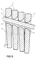
- the cooling element 11 On its front and rear faces 12 and 13, the cooling element 11 has an orifice through 14 flared, substantially hyperbolic axial section and radial section substantially circular with a diameter substantially greater than that of the helical tube 8 so that, as can be seen in Figure 8, the lower rear end 15 of the through hole 14 is not in contact with said tube 8 and that the end upper rear 16 of the orifice 14 is tangent to said helical tube 8, this point of contact 16 constituting the sole fulcrum of the cooling element 11 on the tube helical 8.
- the through hole 14 is extended downwards by a slot 17 so that the cooling element 11 has below the through hole 14 and each side of the slot 17 two legs 18 and 19.
- the front face 12 of the cooling element 11 is flat while the rear face 13 has a clearance angle ⁇ from the fulcrum 16 in the part of the cooling element 11 which is below the through orifice 14. This design means that the center of gravity of the cooling element 11 is located below the fulcrum 16 and that it is axially offset from said point bearing 16 in the direction of movement of this element on the helical tube 8.
- the front and rear faces 12 and 13 form an angle ⁇ , varying the thickness of the cooling element 11, the thickest part being located outside when the refrigerating elements 11 are placed on the helical tube 8. Thus they support one on the others over the entire surface of the faces 12 and 13 above the through hole 14 when they move on said helical tube 8.
- the through hole 14 and the slot 17 are off-center on the side of the thickest part of the cooling element 11 so as to balance the distribution of the substance contained in the cooling element 11 between the legs 18 and 19.
- Said substance is a eutectic mixture whose melting point is for example equal to -16 ° C.
- the helical tube 8 has one end lower or lower zone 28 which extends towards a first zone called "gripping station" To refrigerating elements 11 charged with frigories, said zone being placed behind the wall 3 in which the inlet / outlet orifice 4 is formed. length of the helical tube 8 is such that the last cooling element 11 charged with frigories is no longer carried by said helical tube 8 but is simply held between the wall of the gripping station A and the penultimate cooling element 11 charged with frigories. Insulating material is placed around the gripping station A in order to isolate it from the outside. Above said gripping station A is a zone of transfer B, separated from the gripping station A by a hatch 31 provided with a system reminder (not shown). Transfer zone B communicates with the outside by the inlet / outlet orifice 4 in the wall 3 of the box 2. It is therefore at temperature ambient.
- a slide 30 which can move vertically along the wall 3 of the gripping station A towards a second zone called “pushing station” C of the refrigerating elements 11 to be recycled, the thrust C being located above transfer zone B.
- the slider 30 is actuated by an electric motor 50 and a pinion / rack transmission, the rack 51 being provided on the back of said slide 30. This is guided in translation by two vertical guides 54 and 55 provided on the casing 2 by means of rollers 52 and 53.
- the lower part of the slide 30 is extended by an M-shaped clamp 35, shown in Figure 5.
- Said clamp 35 is fixed to the slide by a pivot 38 at the "tip" of the M and comprises two articulated branches 36, 37 by two pivots 36 'and 37 '.
- the ends of the branches 36, 37 end in two jaws 39 and 40 of shape complementary to the notches 24 and 25 of the cooling element 11.
- Both branches 36, 37 are connected by a transverse bar 41 with respect to which they can pivot freely thanks to two pivots 36 "and 37".
- Crossbar 41 keeps substantially the same gap between the two branches 36, 37, this gap being substantially greater than the width of the cooling element 11.
- the upper end of the slide 30 has a window 42 cut out so as to have a shape complementary to the cooling element 11.
- the lower edge 43 of the window 42 comprises a vertical plate 44 of complementary shape to the slot 17 of the cooling element 11.
- This plate 44 constitutes an orientation device in order to correctly place the refrigerant to be recycled.
- This orientation device can also be provided in the inlet / outlet 4.
- a cleaning 48 of the refrigerating elements 11 to be recycled In the upper part of transfer area B there is a cleaning 48 of the refrigerating elements 11 to be recycled. It consists of an injector sanitizer, two brushes and two squeegees arranged on both sides from window 42.
- the injector is supplied by a liquid reservoir (not shown) comprising a sanitizing product added with a cleaning product and agents defoamer in an aqueous medium.
- the brushes are actuated by pinions meshed in another pinion in direct contact with the same rack 51 which actuates the slide 30.
- the pushing station C is isolated from the outside by an insulating material and separated from the transfer zone B by a hatch 32 provided with a reminder system (not represented). It includes a rocker 45, fixed on a toothed wheel 46 in direct engagement with the same rack 51 which actuates the slide 30.
- the rocker 45 is width substantially less than that of window 42 in slider 30. It is positioned in the pushing station C so as to be substantially the same height than the guide rail 9 extending the upper end or upper zone 29 of the helical tube 8.
- the length of the slider 30 is such that the clamp 35 is facing the inlet / outlet 4 when the window 42 is facing the rocker 45 and such that the window 42 is facing the inlet / outlet 4 when the clamp 35 is opposite the lower end 28 of the helical tube 8.
- the operation and use of the dispenser 1 of refrigerant elements 11 are particularly simple. Indeed, the dispensing device 1 is placed, for example near the shelves of frozen products in a large area. Depending on the space available or the location chosen, the dispensing device 1 can be used as a single or double-sided dispensing face and then comprises one or two refrigerated storage units 7. Before putting into service, the refrigerated storage unit 7 is filled with cooling elements 11 loaded with frigories which can be previously stored on a pallet in freezers. Thanks to an access door (not shown), the personnel of the large area can arrange the refrigerating elements 11 loaded with frigories on the helical tube or tubes 8, 8 ′.
- the slide 30 descends into the gripping station A by pushing on the hatch 31 to open it.
- the gripping station A at the end of the tube helical 8, there is a cooling element 11 charged with frigories.
- the jaws 39 and 40 of the articulated branches 36 and 37 of the clamp 35 come into contact upper edges of the refrigerating element 11 charged with frigories, these deviate and pivot slightly thanks to the different pivots 36 ', 37', 36 ", 37" and 38 for cooperate with the notches 24 and 25 of the refrigerating element 11 charged with frigories.
- the jaws 39 and 40 then hold in the clamp 35 the cooling element 11 loaded with frigories without tightening it.
- a limit switch (not shown) used to determine the end of the slide's downward movement. Then the slide 30 goes up towards transfer zone B, the cooling element charged with frigories being maintained by the clamp 35. The hatch 31 closes thanks to its system after the slider 30 has left gripping station A. In the area transfer B, the slider 30 rises sufficiently so that the clamp 35 arrives at height of the inlet / outlet port 4. A limit switch (not shown) allows the slider 30 to stop in the correct position. Then the client opens the safety hatch 5 and grips the cooling element 11 charged with frigories by the orifice inlet / outlet 4 for example through the through hole 14 and puts it in its insulated bag. Once the safety hatch 5 is closed, the slide 30 goes back down to the position of rest.
- the customer brings back a cooling element to be recycled and wishes exchange it for a refrigerant loaded with frigories, it presses the button command to select the exchange of cooling elements.
- the exchange service can be free or paid and the control unit is then programmed accordingly.
- the slide 30 was in the rest position. Once the control unit operates the motor 50 and the rack 51, the slide 30 descends to the gripping station A and in this zone, the clamp 35 works in the same way as what has been described previously for the sale of refrigerant without exchange.
- the clamp 35 is in look at the lower end 28 of the helical tube 8 and grips a cooling element 11 loaded with frigories.
- the window 42 is located opposite the inlet / outlet port 4.
- the customer manually opens the safety hatch 5.
- Two limit switches (not shown) stop all operation of the device as soon as the safety hatch is lifted.
- the customer can then enter his element refrigerant to be recycled through said inlet / outlet orifice 4, in said window 42.
- the gripping the cooling element 11 is facilitated by the notches 24 and 25.
- the orientation device constituted by the plate 44 on the lower edge 43 of the window 42, the customer can only put his refrigerating element to recycle in one meaning.
- the safety hatch 5 closes under the action of its return spring as soon as the customer released it once the refrigerant to be recycled is in place.
- the slide 30 goes up towards the upper part of transfer zone B so that the refrigerating element 11 to be recycled passes through the cleaning device 48.
- sanitizer is sprayed onto the element refrigerant to be recycled which is then cleaned using brushes and dried by squeegees.
- the slide continues to move upward while cleaning the the refrigerating element to be recycled and reaches the pushing station C after having open the hatch 32 by simple push.
- a limit switch (no shown) allows the slide 30 to stop in the position shown on the Figure 6 such that the refrigerating element 11 to be recycled is located opposite the end upper 29 of the guide rail 9 and such that the window 42 is located substantially the same height as the rocker 45.
- the rack 51 meshes with the toothed wheel 46 on which the rocker is mounted 45 fixedly so that said rocker 45 pivots by an angle ⁇ in the direction of the refrigerating element 11 to be recycled.
- the rocker 45 then pushes the cooling element 11 to be recycled so that it is fitted on the guide rail 9 then on the tube helical 8.
- the fitting of the cooling element 11 to be recycled on the tube helical 8 is particularly facilitated by the flared shape of the through orifice 14.
- the clamp 35 holding the cooling element 11 charged with frigories is located opposite the entry / exit port 4.
- the customer opens the hatch security 5 to allow it to take said refrigerating element loaded with frigories.
- the slide 30 descends into transfer zone B, the hatch 32 which closes with its return system and the slider 30 is replaced by rest position awaiting a new request.
- Displacement is favored by the fact that the elements refrigerants 11 in the upper part of the refrigerated storage unit 7 push the refrigerating elements 11 in the lower part of the refrigerated storage unit 7. If the speed of the cooling elements during their descent on the helical tube 8 becomes too large and the cooling elements offset due to the force centrifugal, the friction of the legs 18 or 19 on the guide rail 9 makes it possible to brake naturally the cooling elements 11.
- a counter is provided in the dispensing apparatus manage the inputs and outputs of the cooling elements and signal the decrease in stock from a predefined alarm threshold.
- the dispenser of cooling elements according to the invention makes it possible to store 415 cooling elements per refrigerated storage unit.
- the dispensing device 101 essentially differs from device 1 described above by the presence of two separate ports, an inlet port and a outlet orifice, and by removing the transfer slide 30 and its system training. These differences make it possible to further simplify the device 101, reducing its cost, its size and its maintenance.
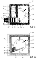
- This device 101 of form substantially square, comprises a box 102, a wall 103 of which has, in part high, an inlet port 104 and, at the bottom, an outlet port 105.
- a traditional operating coin mechanism 106 located substantially at the same height as the inlet and connected to a control unit and electronic management 109 provided inside the device in the upper part.
- the arrangement of these various elements can be modified.
- the box 102 contains a device evaporation and ventilation 149, a storage unit 107 refrigerated by a traditional cold generating device 150 provided under the appliance 101.
- the storage 107 is isolated from the walls of the casing 102 by injected foam or foam plates and includes a helical rail for storage and guide 108, of flat section, replacing the previous storage tube 8 and guide rail 9 but with the same functionality. Its design allows a reduction in diameter and pitch of the propeller thus increasing the storage capacity of refrigerating elements 11 by reducing the space required.
- the turns that make up this rail 108 make an angle of between 8 ° and 15 ° approximately with the horizontal.
- This helical rail 108 extends from one end or upper zone 129 located substantially at the same height as the inlet port 104 toward one end or lower zone 128 situated substantially at the same height as the outlet orifice 105.
- This helical rail 108 is fixed to the interior walls of the storage unit 107, or could be fixed to a central support tube (not shown), by means of brackets 110 in a U shape distributed regularly along said rail, for example, all 90 °.
- the helical rail 108 is arranged to receive a plurality of cooling elements 11 identical to those described above.
- the inlet 104 is oriented substantially horizontally and has a shape complementary to that of a refrigerating element 11 to be recycled presented lying in direction of orifice 104.
- the shape of inlet port 104 slightly conical allows correct orientation of the cooling element 11 to be recycled.
- This element refrigerant 11 can be introduced by its legs 18, 19 as well as by its face upper 26.
- Three limit switches or recognition cells 111a, 111b and 111c are arranged directly behind the inlet port 104, two of which side 111a and 111b detectors and an upper or lower 111c detector of so as to be placed above the slot 17 of the cooling element 11.
- a cleaning device 112 for the refrigerating elements 11 to be recycled is provided between this inlet 104 and the storage unit 107.
- This cleaning device 112 comprises several pairs of cylindrical brushes 113, and in this case three pairs, rotating, arranged one after the other, the brushes of each pair being spaced to define a more or less narrow passage to receive the element refrigerant 11 to be recycled, this passage being arranged in the extension of the orifice inlet 104.
- An injector 114 is provided in the upper part of the cleaning 112 and allows the spraying of a sanitizing product added with a cleaning product and anti-foaming agents in an aqueous medium, this product coming from a liquid tank 115 and a pump 116.
- This sanitizing product is then recovered and evacuated by a pipe 115 'to the condensate recovery tank of the cold group 150, this pipe passing through the walls of the box 102.
- the rotation of the brushes 113 is controlled by a suitable drive device and, by example, a small motor coupled to the different brushes by means of a train gear or toothed belt and pinions.
- Brush rotation 113 drives the cooling element 11 to be recycled to and into the storage unit 107 through a sealed door 117.
- This sealed door 117 comprises for example flat brushes and rubber slats.
- Fixed friction elements 113 ' are arranged laterally and parallel to the direction of movement of the cooling element 11 driven by the brushes 113 and are arranged to rub against the side faces 22, 23 of said cooling element 11 in order to brake it to create a speed differential between it and said brushes and allow the latter to clean it effectively.
- These friction elements 113 ′ consist for example of brushes, rubber pads or other suitable devices.
- the refrigerating element 11 to be recycled After the passage of the sealed door 117, the refrigerating element 11 to be recycled, not being more guided, tilts under the effect of its weight and is positioned directly on the rail helical 108 for storage and guidance which starts just after the watertight door 117.
- Upper guide blades 118 and side guides 119 are provided at the outlet of the watertight door 117 and above the upper zone 129 of the helical rail 108 and are arranged to correctly position the cooling element 11 to be recycled on the helical rail 108, even if the latter is introduced by its upper face 26.
- the refrigerating element 11 to be recycled descends along the helical rail 108 until it meets the other refrigerating elements 11 which are already stored. Meanwhile, it recharges in frigories.
- the helical rail 108 ends in a straight portion substantially perpendicular to the outlet orifice 105 and stops to release a refrigerant element 11 loaded with frigories and position it against a guide wall 126 so that it is substantially opposite the orifice of outlet 105.
- This outlet orifice 105 is oriented substantially vertically or slightly inclined and has a shape complementary to that of the element refrigerant 11 charged with frigories in a standing position and oriented in profile.
- This orifice 105 is separated from the storage unit 107 by a watertight door 120 comprising by example of flat brushes and rubber slats.
- a jack 121 is mounted on the guide wall 126 for pushing the refrigerant element 11 loaded with frigories to through the watertight door 120 towards the outlet orifice 105, this jack being controlled by the control and management unit 109 as a function of the limit switches 111a, 111b and 111c and / or the coin mechanism.
- the rod of this jack 120 moves parallel to the guide wall 126 and the outlet orifice 105 and has a rounded end 122 complementary to the semi-cylindrical notch 24 provided in the refrigerating element 11 in which it bears.
- Stops 123 are provided at the outside of the wall 103 of the apparatus 101, above and below the orifice of outlet 105, to keep the refrigerating element 11 loaded with frigories in position and facilitate its grip by the user.
- the control and management unit 109 provided in this device 101 is a device known and marketed under the brand VISIOCOM TM which can be compared to an automaton which makes it possible to control and manage, remotely, the generator group of cold 150, ordering brushes 113 and cylinder 121, stock of elements refrigerants 11 contained in the device 101, the level of the sanitizing product. He offers thus a very appreciable flexibility of use and management.
- a socket telephone 124 is provided at the back of the casing 102 in addition to a socket power supply 125 of the device which plugs into the 220 V sector with Earth.
- the present invention is not limited to the embodiments described but extends any modification and variant obvious to a person skilled in the art.
- the slide provided in the first variant can be replaced by any equivalent means of transfer.
- the slide, the cleaning device and the rocker can be respectively actuated by actuation means equivalent to the rack.
- the device according to the second variant can also be provided with a double storage unit. Means of transfer by brushes 113 and cylinder 121 could be different.
- the element dispensing device refrigerants has been described here as being used in a large area. The walls can serve as advertising media to promote new products.
- a location 127 with 220V power outlet is provided on the part top of the dispenser to install a VCR and TV to inform customers.
- campers or vacationers have the possibility of always having a refrigerant loaded with frigories in their cooler. This allows them to transport their food in peace and throughout the journey.
- an anti-vandalism device can be provided for dispensing devices placed outside.
Landscapes
- Engineering & Computer Science (AREA)
- Physics & Mathematics (AREA)
- General Physics & Mathematics (AREA)
- Combustion & Propulsion (AREA)
- Mechanical Engineering (AREA)
- Thermal Sciences (AREA)
- General Engineering & Computer Science (AREA)
- Chemical & Material Sciences (AREA)
- Devices That Are Associated With Refrigeration Equipment (AREA)
- Control Of Vending Devices And Auxiliary Devices For Vending Devices (AREA)
- Vending Machines For Individual Products (AREA)
- Commercial Cooking Devices (AREA)
- Thermistors And Varistors (AREA)
- Containers, Films, And Cooling For Superconductive Devices (AREA)
- Warehouses Or Storage Devices (AREA)
- Amplifiers (AREA)
Claims (27)
- Ausgabeautomat (1, 101) für Kühlelemente (11), insbesondere für Platten und Säckchen, die eine Substanz enthalten, die formuliert wurde, um Kälte zu akkumulieren, bestehend aus einem Schrank (2, 102), der mindestens eine Speichereinheit (7, 107) für die besagten Kühlelemente enthält, wobei die besagte Speichereinheit durch eine Kälte erzeugende Vorrichtung abgekühlt wird, die angeordnet ist, um die besagten Kühlelemente (11) mit kühlen, aus Transportmitteln (30, 121) zur Beförderung von mindestens einem gelagerten und gekühlten Kühlelement aus der Kühllagereinheit (7, 107) in Richtung mindestens einer in einer Wand (3, 103) des Schranks (2, 102) angeordneten Ausgangsöffnung (4, 105), und aus Steuerelementen, die angeordnet sind, um die besagten Transportmittel (30, 121) zu aktivieren, dadurch gekennzeichnet, daß die besagte Kühllagereinheit (7, 107) ein spiralförmiges Rohr (8, 108) aufweist, das sich in Richtung der Ausgangsöffnung (4, 105) hin erstreckt, so daß die Kühlelemente (11) sich in dem Verlauf ihrer Lagerung zum Ausgang hin bewegen.
- Ausgabeautomat (1, 101) gemäß Anforderung 1, dadurch gekennzeichnet, daß der Schrank (2, 102) ebenfalls Transportmittel (30, 113) enthält, um wenigstens ein wiederzuverwendendes Kühlelement (11) von mindestens einer in einer Wand (3, 103) des Schranks (2, 102) angeordneten Eintrittsöffnung (4, 104) aus zu befördern, sowie Steuerelemente, die angeordnet sind, um die besagten Transportmittel (30, 113) zu aktivieren, um das besagte wiederzuverwendende Kühlelement (11) von der besagten Eintrittsöffnung (4, 104) in Richtung der Kühllagereinheit (7, 107) zu befördern.
- Ausgabeautomat (1, 101) gemäß Anforderung 2, dadurch gekennzeichnet, daß das spiralförmige Rohr (8, 108), entlang seines unteren Mantels eine flachförmige Führungsschiene (9, 108) aufweist, so daß die Kühlelemente (11) während ihres Transportes zur Kühllagereinheit (7, 107) geführt werden.
- Ausgabeautomat (101) gemäß Anforderung 3, dadurch gekennzeichnet, daß das spiralförmige Rohr und das Transportband ein einziges, spiralförmige Lagerungs- und Führungsschiene (108) benanntes Teil bilden, dessen Querschnitt flach ist.
- Ausgabeautomat (1, 101) gemäß Anforderung 3 oder 4, dadurch gekennzeichnet, daß er eine Reinigungsvorrichtung (48, 112) enthält, die sich auf der Strecke der besagten wiederzuverwendenden Kühlelemente befindet, zwischen der Eintrittsöffnung (4, 104) und der Kühllagereinheit (7, 107), und die angeordnet ist, um die besagten Elemente (11) zu reinigen und von Keimen zu befreien.
- Ausgabeautomat (1, 101) gemäß Anforderung 5, dadurch gekennzeichnet, daß die Reinigungsvorrichtung (48, 112) einen Injektor (117), der ein sterilisierendes Produkt abgibt, und mindestens eine Bürste (113) enthält, um die wiederzuverwendenden Kühlelemente (11) zu reinigen.
- Ausgabeautomat (1) gemäß Anforderung 2, dadurch gekennzeichnet, daß die Transportmittel (30) zur Beförderung von mindestens einem gelagerten und gekühlten Kühlelement (11) in Richtung der Austrittsöffnung (4) und die Transportmittel (30) zur Beförderung von mindestens einem wiederzuverwendenden Kühlelement (11) von der Eintrittsöffnung (4) aus eine selbe Transportvorrichtung (30) für die Kühlelemente (11) bilden, dadurch, daß die Eintrittsöffnung und die Austrittsöffnung eine gemeinsame Eintritts-/Austrittsöffnung (4) für die wiederzuverwendenden, bzw. gekühlten Kühlelemente (11) bilden, so daß durch die besagte Transportvorrichtung (30) ein gekühltes Kühlelement (11) von einer unteren Zone (28) der Kühllagereinheit (7) in Richtung der Eintritts-/Austrittsöffnung (4) befördert wird, während ein wiederzuverwendendes Kühlelement (11) von der Eintritts-/Austrittsöffnung (4) zu einer höheren Zone (29) der Kühllagereinheit (7) befördert wird, und dadurch, daß das besagte spiralförmige Rohr (8) sich von der besagten oberen Zone (29) zu der besagten unteren Zone (28) hin erstreckt, so daß sich die Kühlelemente (11) im Laufe ihrer Lagerung in Richtung der Basis der Transportvorrichtung (30) bewegen.
- Ausgabeautomat (1) gemäß Anforderung 7, dadurch gekennzeichnet, daß die Transportvorrichtung einen mit Greifmitteln (35, 42) für die Kühlelemente (11) ausgestatteter Schieber (30) beträgt, der angeordnet ist, um sich senkrecht entlang der Wand (3) des Schranks (2) zu bewegen, in welcher sich die Eintritts-/Austrittsöffnung (4) befindet, sowie Schiebemittel (45) für die wiederzuverwendenden Kühlelemente (11), die angeordnet sind, um das von dem Schieber (30) kommende wiederverwendbare Kühlelement (11) in die Kühllagereinheit (7) abzulegen.
- Ausgabeautomat (1) gemäß Anforderung 8, dadurch gekennzeichnet, daß die Greifmittel (35, 42) für die Kühlelemente (11) erste Greifmittel (35) für die gekühlten Kühlelemente (11), die merklich in dem unteren Teil des Schiebers (30) angeordnet sind, und zweite Greifmittel (42) für die wiederzuverwendenden Kühlelemente (11), die merklich in dem oberen Teil des Schiebers (30) angeordnet sind, betragen, und dadurch, daß die besagten Schiebemittel (45) für die wiederzuverwendenden Kühlelemente (11) so in der zweiten Zone (29) angeordnet sind, daß die zweiten Greifmittel (42) das wiederzuverwendende Kühlelement (11) durch die Eintritts-/Austrittsöffnung (4) empfangen, während die besagten ersten Greifmittel (35) das gekühlte Kühlelement (11). der Kühllagereinheit (7) entnehmen, und so daß die Schiebemittel (45) das besagte wiederzuverwendende Kühlelement (11) in der Kühllagereinheit (7) ablegen, während die ersten Schiebemittel (35) das gekühlte Kühlelement (11) in die Eintritts-/Austrittsöffnung (4) befördern.
- Ausgabeautomat (1) gemäß Anforderung 9, dadurch gekennzeichnet, daß die ersten Greifmittel (35) einen Greifer mit zwei beweglichen Armen (36, 37) aufweisen, der angeordnet ist um ein gekühltes Kühlelement (11) an seinen Seiten (22, 23) zu greifen, wobei die Enden der besagten Arme (36, 37) Klemmbacken (39, 49) aufweisen.
- Ausgabeautomat (1) gemäß der Anforderung 9, dadurch gekennzeichnet, daß die zweiten Greifinittel (42) eine im Schieber (30) vorgesehene Öffnung (42) betragen, dessen Form das Gegenstück zum Kühlelement (11) aufweist.
- Ausgabeautomat (1) gemäß Anforderung 9, dadurch gekennzeichnet, daß die Schiebemittel (45) eine Wippe (45) aufweisen, die angeordnet ist um das wiederzuverwendende Kühlelement (11) auf das spiralförmige Rohr (8) zu schieben.
- Ausgabeautomat (1) gemäß irgendeiner der vorhergehenden Anforderungen, dadurch gekennzeichnet, daß die Steuerelemente angeordnet sind um den Schieber (30), die Schiebemittel (45) und die Reinigungsvorrichtung (48) mittels eines gemeinsamen Mechanismus anzutreiben.
- Ausgabeautomat (1) gemäß Anforderung 13, dadurch gekennzeichnet, daß der besagte Mechanismus mindestens eine Zahnstange (51) beträgt, die sich entlang des Schiebers (30) erstreckt, und dadurch, daß die Schiebemittel (45) und die Reinigungsvorrichtung (48) jeweils mindestens ein Antriebsritzel betragen, das angeordnet ist um mit der besagten Zahnstange (51) zusammenzuwirken.
- Ausgabeautomat (101) gemäß Anforderung 2, dadurch gekennzeichnet, daß die Transportmittel (113, 121) unterschieden sind, dadurch, daß die Eintritts- (104) und Austrittsöffnungen (105) unterschieden sind, wobei die Eintrittsöffnung (104) in der Nähe der oberen Zone (129) der Lagereinheit (107) angeordnet ist und die Austrittsöffnung (105) in der Nähe der unteren Zone (128) der Lagereinheit (107) angeordnet ist, und dadurch, daß das spiralförmige Rohr (108) sich von der besagten oberen Zone (129) zur besagten unteren Zone (128) hin erstreckt, so daß die Kühlelemente (11) in dem Verlauf ihrer Lagerung in Richtung der unteren Zone (128) gefördert werden.
- Ausgabeautomat (101) gemäß Anforderung 15, dadurch gekennzeichnet, daß die Transportmittel (121) einen Zylinder (121) aufweisen, der angeordnet ist um ein gekühltes Kühlelement (11) von der Lagereinheit (107) zur Austrittsöffnung (104) zu schieben, wobei dieses Kühlelement das spiralförmige Rohr (108) verlassen hat und auf einer Führungswand (126) aufliegt, damit es sich gegenüber der besagten Austrittsöffnung (105) befindet.
- Ausgabeautomat (101) gemäß Anforderung 15, dadurch gekennzeichnet, daß die Transportmittel (113), mindestens zwei parallele und zylindrische, in Drehung angetriebene Bürsten (113) aufweisen, die angeordnet sind, um das besagte wiederzuverwendende Kühlelement (11) zwischen sich zu verschieben, und zwar von der Eintrittsöffnung (104) bis zur Lagereinheit (107), sowie mindestens ein Reibungselement (113'), das parallel zur Bewegungsrichtung des besagten Kühlelementes (11) und gegen dieses angeordnet ist, um es abzubremsen.
- Ausgabeautomat (101) gemäß irgendeiner der Anforderungen 15 bis 17, dadurch gekennzeichnet, daß er mindestens einen in dem hinteren Teil der Eintrittsöffnung (104) eingebauten Detektor (111a, 111b, 111c) aufweist, der angeordnet ist um die Anwesenheit eines wiederverzuwendenden Kühlelementes (11) festzustellen, wobei dieser Detektor (111) mit den Steuerelementen (109) der Transportmittel (113, 121) verbunden ist.
- Ausgabeautomat (101) gemäß Anforderung 18, dadurch gekennzeichnet, daß er zwei seitliche Detektoren (111a, 111b) und einen oberen oder unteren Detektor (111c) aufweist, die angeordnet sind um die Form des Kühlelementes (11) zu erkennen.
- Ausgabeautomat (101) gemäß irgendeiner der Anforderungen 15 bis 19, dadurch gekennzeichnet, daß er am Ein- und am Ausgang der Kühllagereinheit (107) befindliche hermetische Türen (117, 120) besitzt, wobei diese Türen flache Bürsten und Gummilamellen betragen.
- Verteilerapparat (1, 101) gemäß irgendeiner der vorhergehenden Anforderungen, dadurch gekennzeichnet, daß er außerdem einen Münzapparat (6, 106) enthält, der mit den Steuerelementen (109) verbunden ist, einerseits für den Verkauf eines gekühlten Kühlelementes (11), andererseits für die Auslieferung eines gekühlten Kühlelementes (11) im Tausch gegen ein wiederzuverwendendes Kühlelement (11).
- Kühlelement (11), das eine Substanz enthält, die formuliert wurde, um Kälte zu akkumulieren, zur Verwendung in einem Ausgabeautomat (1, 101) gemäß Anforderung 6, dadurch gekennzeichnet, daß es eine merklich rechteckige plattenförmige Form aufweist und eine durchgehende breite, auf seinen Seiten (12, 13) endende Öffnung (14) besitzt, mit einem merklich kreisförmigen Radialschnitt, dessen Durchmesser merklich größer ist, als der der spiralförmigen Rohrs (8, 108), so daß der hintere, untere Teil (15) der durchgehenden Öffnung (14) keinen Kontakt mit dem besagten Rohr (8, 108) hat und der hintere, obere Teil (16) der Öffnung (14) tangential an dem besagten spiralförmigen Rohr (8, 108) anliegt, wobei dieser Kontaktpunkt den Stützpunkt (16) für das Kühlelement (11) auf dem spiralförmigen Rohr (8, 108) darstellt.
- Kühlelement (11) gemäß Anforderung 22, dadurch gekennzeichnet, daß es einen Spalt (17) aufweist, der eine Verbindung zwischen der besagten durchgehenden Öffnung (14) und dem äußeren Teil des Kühlelementes (11) herstellt, wobei der besagte Spalt (17) eine komplementäre Form zu derjenigen der auf dem spiralförmigen Rohr vorgesehenen Führungsschiene (8, 108) darstellt.
- Kühlelement (11) gemäß Anforderung 23, dadurch gekennzeichnet, daß es an seinen Seiten (22, 23) Kerben (24, 25) aufweist, die das Greifen durch die besagten Transportmittel (30, 121) erlauben.
- Kühlelement (11) gemäß irgendeiner der Anforderungen 22 bis 24, dadurch gekennzeichnet, daß es so konstruiert ist, daß sein Schwerpunkt unterhalb des besagten Stützpunktes (16) liegt, und dadurch, daß der Schwerpunkt axial in Bezug auf den besagten Stützpunkt (16) in der Richtung seiner Bewegung auf dem spiralförmigen Rohr (8, 108) verschoben ist.
- Kühlelement (11) gemäß irgendeiner der Anforderungen 22 bis 25, dadurch gekennzeichnet, daß das Kühlelement (11) einen Freiwinkel (β) aufweist, der unterhalb des besagten Stützpunktes (16) liegt, wobei der besagte Winkel durch den Neigungswinkel seiner hinteren Seite (13) unter der durchgehenden Öffnung (14) gebildet wird.
- Kühlelement (11) gemäß irgendeiner der Anforderungen 22 bis 26, dadurch gekennzeichnet, daß die Substanz, die es enthält, aus einer eutektischen Flüssigkeit besteht.
Applications Claiming Priority (3)
| Application Number | Priority Date | Filing Date | Title |
|---|---|---|---|
| FR9603192 | 1996-03-11 | ||
| FR9603192A FR2745933B1 (fr) | 1996-03-11 | 1996-03-11 | Appareil distributeur d'elements refrigerants et lesdits elements refrigerants |
| PCT/FR1997/000404 WO1997034264A1 (fr) | 1996-03-11 | 1997-03-07 | Appareil distributeur d'elements refrigerants et lesdits elements refrigerants |
Publications (2)
| Publication Number | Publication Date |
|---|---|
| EP0824739A1 EP0824739A1 (de) | 1998-02-25 |
| EP0824739B1 true EP0824739B1 (de) | 2000-09-13 |
Family
ID=9490171
Family Applications (1)
| Application Number | Title | Priority Date | Filing Date |
|---|---|---|---|
| EP97908319A Expired - Lifetime EP0824739B1 (de) | 1996-03-11 | 1997-03-07 | Ausgabeautomat für kühlelemente und entsprechende kühlelemente |
Country Status (11)
| Country | Link |
|---|---|
| US (1) | US6056152A (de) |
| EP (1) | EP0824739B1 (de) |
| JP (1) | JP4016401B2 (de) |
| AT (1) | ATE196379T1 (de) |
| AU (1) | AU710304B2 (de) |
| CA (1) | CA2221049C (de) |
| DE (1) | DE69703073T2 (de) |
| ES (1) | ES2154029T3 (de) |
| FR (1) | FR2745933B1 (de) |
| PT (1) | PT824739E (de) |
| WO (1) | WO1997034264A1 (de) |
Families Citing this family (20)
| Publication number | Priority date | Publication date | Assignee | Title |
|---|---|---|---|---|
| US6085534A (en) * | 1999-03-19 | 2000-07-11 | Anthony; Michael M. | Non-electric refrigerating vending machine |
| US6173582B1 (en) * | 1999-04-16 | 2001-01-16 | Sta-Kul, L.L.C. | Self-dispensing portable cooler |
| US6505754B1 (en) * | 2000-01-25 | 2003-01-14 | Spectrum Composities, Inc. | Apparatus for automated key retrieval and deposit |
| FR2807190B1 (fr) | 2000-03-29 | 2002-06-28 | Internova Int Innovation | Appareil distributeur d'elements refrigerants rechargeables |
| US8475484B2 (en) * | 2000-04-05 | 2013-07-02 | Medrad, Inc. | Liquid seal assembly for a rotating torque tube |
| US6371311B1 (en) * | 2000-07-10 | 2002-04-16 | L&P Property Management Company | Rack for storing product |
| GB2393715A (en) * | 2002-08-19 | 2004-04-07 | Diageo Great Britain Ltd | A sispenser |
| FR2871272B1 (fr) * | 2004-06-04 | 2006-08-18 | Cool Sarl Sarl Soc | Procede et appareillage pour effectuer une distribution individuelle d'espaces fermes froids destines a garder au froid des denrees alimentaires ou des substances medicamenteuses ou equivalentes |
| JP5267313B2 (ja) * | 2009-05-13 | 2013-08-21 | 富士電機株式会社 | 自動販売機 |
| FR2959336B1 (fr) * | 2010-04-22 | 2012-06-29 | Gerard Kuma | Armoire de distribution automatique de balles de tennis refrigerante |
| FR2992406A1 (fr) * | 2012-06-26 | 2013-12-27 | Futurinov | Distributeur passif d'accumulateurs de froid et accumulateur de froid associe |
| CN103530941A (zh) * | 2013-09-27 | 2014-01-22 | 申烽 | 一种售餐机 |
| CN106196871B (zh) * | 2015-02-28 | 2019-01-08 | 重庆工商职业学院 | 一种储物冰箱 |
| WO2017039662A1 (en) * | 2015-09-02 | 2017-03-09 | Cerny Sherry J | Frozen freezer pack |
| US11426329B2 (en) * | 2019-11-12 | 2022-08-30 | Omnicell, Inc. | Dispensing systems and methods for prefilled syringes |
| CN111606002B (zh) * | 2020-05-26 | 2020-12-25 | 隆链智能科技(上海)有限公司 | 一种自清洁agv转运车 |
| CN111721044A (zh) * | 2020-06-17 | 2020-09-29 | 珠海格力电器股份有限公司 | 一种冰箱及冰箱储藏室内食材取放方法 |
| CN112274990B (zh) * | 2020-11-02 | 2021-08-03 | 温岭市兴风食品有限公司 | 一种生鲜冷链物流保存运输方法 |
| DE102023104628A1 (de) * | 2023-02-24 | 2024-08-29 | Viessmann Refrigeration Solutions Gmbh | Regenerationsmagazin zur aktiven Regeneration von entladenen Temperierelementen |
| DE102023104629A1 (de) * | 2023-02-24 | 2024-08-29 | Viessmann Refrigeration Solutions Gmbh | Regenerationsmagazin zur aktiven Regeneration von entladenen Temperierelementen |
Family Cites Families (12)
| Publication number | Priority date | Publication date | Assignee | Title |
|---|---|---|---|---|
| US1789300A (en) * | 1926-08-26 | 1931-01-20 | Iron Mountain Co | Dispensing apparatus |
| US2562288A (en) * | 1950-01-20 | 1951-07-31 | Westinghouse Electric Corp | Vending apparatus |
| US2804958A (en) * | 1954-01-25 | 1957-09-03 | Garrard Bruce | Bottle vending machine |
| US2805841A (en) * | 1956-04-04 | 1957-09-10 | Armstrong Cork Co | Cooling system for conveyors |
| DK126066B (da) * | 1971-02-15 | 1973-06-04 | J Christensen | Automat til udlevering af genstande. |
| FR2258672A1 (en) * | 1974-01-17 | 1975-08-18 | Levi Henri | Coin-operated distributor for refrigerated containers - has refrigerated vertical container stack above extract drawer |
| IT7752895U1 (it) * | 1977-02-07 | 1978-08-07 | P Ferrero & C S P A | Espositore per articoli sferici. |
| DE3215627A1 (de) * | 1982-04-27 | 1983-11-03 | Paul Hettler | Kuehlbomben-umlaufsystem mit verkaufs-automatisation |
| EP0140153A3 (en) * | 1983-10-27 | 1986-07-30 | Gyorgy Teglasy | Coin-operated apparatus for dispensing cooling elements |
| IT1209567B (it) * | 1984-07-13 | 1989-08-30 | Lucio Grossi | Distributore automatico per oggetti con vassoi mobili a vite. |
| GB2182917B (en) * | 1985-11-15 | 1988-09-21 | Commw Ind Gases | Exchanging/vending machine for gas cylinders |
| JPH0454589A (ja) * | 1990-06-21 | 1992-02-21 | Fuji Electric Co Ltd | 冷凍商品自動販売機 |
-
1996
- 1996-03-11 FR FR9603192A patent/FR2745933B1/fr not_active Expired - Fee Related
-
1997
- 1997-03-07 US US08/952,198 patent/US6056152A/en not_active Expired - Lifetime
- 1997-03-07 PT PT97908319T patent/PT824739E/pt unknown
- 1997-03-07 CA CA002221049A patent/CA2221049C/fr not_active Expired - Lifetime
- 1997-03-07 DE DE69703073T patent/DE69703073T2/de not_active Expired - Lifetime
- 1997-03-07 AT AT97908319T patent/ATE196379T1/de active
- 1997-03-07 EP EP97908319A patent/EP0824739B1/de not_active Expired - Lifetime
- 1997-03-07 JP JP53232197A patent/JP4016401B2/ja not_active Expired - Lifetime
- 1997-03-07 AU AU20313/97A patent/AU710304B2/en not_active Expired
- 1997-03-07 ES ES97908319T patent/ES2154029T3/es not_active Expired - Lifetime
- 1997-03-07 WO PCT/FR1997/000404 patent/WO1997034264A1/fr not_active Ceased
Also Published As
| Publication number | Publication date |
|---|---|
| ES2154029T3 (es) | 2001-03-16 |
| JP4016401B2 (ja) | 2007-12-05 |
| DE69703073T2 (de) | 2001-05-03 |
| AU710304B2 (en) | 1999-09-16 |
| FR2745933B1 (fr) | 1998-06-12 |
| AU2031397A (en) | 1997-10-01 |
| US6056152A (en) | 2000-05-02 |
| FR2745933A1 (fr) | 1997-09-12 |
| JPH11508075A (ja) | 1999-07-13 |
| ATE196379T1 (de) | 2000-09-15 |
| DE69703073D1 (de) | 2000-10-19 |
| PT824739E (pt) | 2001-03-30 |
| CA2221049A1 (fr) | 1997-09-18 |
| WO1997034264A1 (fr) | 1997-09-18 |
| CA2221049C (fr) | 2006-08-15 |
| EP0824739A1 (de) | 1998-02-25 |
Similar Documents
| Publication | Publication Date | Title |
|---|---|---|
| EP0824739B1 (de) | Ausgabeautomat für kühlelemente und entsprechende kühlelemente | |
| EP1952362B1 (de) | Spender für verzehrbare produkte, wie z. b. getränke | |
| EP0428546B1 (de) | Automatische austeilvorrichtung für flaschen, insbesondere aus elastischem werkstoff | |
| EP1935813A1 (de) | Vorrichtung zur Einzelverteilung von Gegenständen in Stäbchenform | |
| EP1730708A1 (de) | Automatischer spender für voluminöse und/oder schwere produkte und/oder produkte in paketen | |
| EP1269432B1 (de) | Ausgabeautomat für wideraufladbare kühlelemente | |
| EP0233232B1 (de) | Vorrichtung zur verteilung und zum verkauf von biegsamen trägern | |
| EP1386880A1 (de) | Beweglicher und selbständiger Getränkespender | |
| EP0207836A1 (de) | Mit einem hin- und herbewegenden Wagen ausgerüsteter Selbstverkäufer für zylindrische Waren | |
| EP2679940B1 (de) | Passiver Spender von Kältespeichern und Verfahren zur Verwendung eines solchen Spenders | |
| EP0844593A2 (de) | Automatische Ausgabevorrichtung von Nahrungsmittel für Restaurants | |
| FR2866968A1 (fr) | Appareil de distribution automatique de produits volumineux et/ou lourds et/ou vendus en packs | |
| FR2872614A1 (fr) | Appareil de distribution automatique de produits volumineux et/ou lourds et/ou vendus en pack | |
| WO2000021873A1 (fr) | Doseur a manette avec dispositif de givrage | |
| WO2004051368A1 (fr) | Dispositif pour le stockage et la distribution d'objets | |
| FR3131285A1 (fr) | Installation de distribution de boissons dans des recipients notamment de type canette | |
| FR2952916A1 (fr) | Module de stockage de gobelets, par exemple usages, et dispositif de collecte de gobelets usages comportant un tel module. | |
| BE519489A (de) | ||
| WO2006042963A1 (fr) | Dispositif de compactage et vidage de cannettes pour boisson | |
| EP4241889A1 (de) | Vorrichtung zum zerkleinern von glas | |
| FR3116225A1 (fr) | Dispositif de transfert d'une barrique par robot collaboratif, notamment pour le lavage et installation de lavage equipee | |
| FR2597085A1 (fr) | Distributeur de boissons glacees perfectionne | |
| BE893493A (fr) | Distributeur automatique. | |
| EP2389060A2 (de) | Vorrichtung zur lagerung von landwirtschaftsprodukten, insbesondere von langem und biegsamem gemüse, z. b. lauch, und entsprechendes verfahren | |
| FR2731689A1 (fr) | Installation manuelle d'embouteillage de liquides tels que des vins a partir d'un conditionnement en recipient |
Legal Events
| Date | Code | Title | Description |
|---|---|---|---|
| PUAI | Public reference made under article 153(3) epc to a published international application that has entered the european phase |
Free format text: ORIGINAL CODE: 0009012 |
|
| 17P | Request for examination filed |
Effective date: 19971025 |
|
| AK | Designated contracting states |
Kind code of ref document: A1 Designated state(s): AT BE CH DE DK ES FI FR GB IT LI NL PT SE |
|
| GRAG | Despatch of communication of intention to grant |
Free format text: ORIGINAL CODE: EPIDOS AGRA |
|
| GRAG | Despatch of communication of intention to grant |
Free format text: ORIGINAL CODE: EPIDOS AGRA |
|
| 17Q | First examination report despatched |
Effective date: 19990702 |
|
| GRAG | Despatch of communication of intention to grant |
Free format text: ORIGINAL CODE: EPIDOS AGRA |
|
| GRAH | Despatch of communication of intention to grant a patent |
Free format text: ORIGINAL CODE: EPIDOS IGRA |
|
| GRAH | Despatch of communication of intention to grant a patent |
Free format text: ORIGINAL CODE: EPIDOS IGRA |
|
| GRAA | (expected) grant |
Free format text: ORIGINAL CODE: 0009210 |
|
| AK | Designated contracting states |
Kind code of ref document: B1 Designated state(s): AT BE CH DE DK ES FI FR GB IT LI NL PT SE |
|
| PG25 | Lapsed in a contracting state [announced via postgrant information from national office to epo] |
Ref country code: FI Free format text: LAPSE BECAUSE OF FAILURE TO SUBMIT A TRANSLATION OF THE DESCRIPTION OR TO PAY THE FEE WITHIN THE PRESCRIBED TIME-LIMIT Effective date: 20000913 |
|
| REF | Corresponds to: |
Ref document number: 196379 Country of ref document: AT Date of ref document: 20000915 Kind code of ref document: T |
|
| REG | Reference to a national code |
Ref country code: CH Ref legal event code: EP |
|
| REF | Corresponds to: |
Ref document number: 69703073 Country of ref document: DE Date of ref document: 20001019 |
|
| ITF | It: translation for a ep patent filed | ||
| PG25 | Lapsed in a contracting state [announced via postgrant information from national office to epo] |
Ref country code: SE Free format text: LAPSE BECAUSE OF FAILURE TO SUBMIT A TRANSLATION OF THE DESCRIPTION OR TO PAY THE FEE WITHIN THE PRESCRIBED TIME-LIMIT Effective date: 20001213 Ref country code: DK Free format text: LAPSE BECAUSE OF FAILURE TO SUBMIT A TRANSLATION OF THE DESCRIPTION OR TO PAY THE FEE WITHIN THE PRESCRIBED TIME-LIMIT Effective date: 20001213 |
|
| GBT | Gb: translation of ep patent filed (gb section 77(6)(a)/1977) |
Effective date: 20001206 |
|
| REG | Reference to a national code |
Ref country code: CH Ref legal event code: NV Representative=s name: CABINET ROLAND NITHARDT CONSEILS EN PROPRIETE INDU |
|
| REG | Reference to a national code |
Ref country code: CH Ref legal event code: PUE Owner name: LEONETTI, PHILIPPE TRANSFER- INDUSTRIE ET FINANCE |
|
| RAP2 | Party data changed (patent owner data changed or rights of a patent transferred) |
Owner name: INDUSTRIE ET FINANCE S.A. |
|
| REG | Reference to a national code |
Ref country code: ES Ref legal event code: FG2A Ref document number: 2154029 Country of ref document: ES Kind code of ref document: T3 |
|
| REG | Reference to a national code |
Ref country code: PT Ref legal event code: SC4A Free format text: AVAILABILITY OF NATIONAL TRANSLATION Effective date: 20001205 |
|
| NLT2 | Nl: modifications (of names), taken from the european patent patent bulletin |
Owner name: INDUSTRIE ET FINANCE S.A. |
|
| REG | Reference to a national code |
Ref country code: GB Ref legal event code: 732E |
|
| REG | Reference to a national code |
Ref country code: PT Ref legal event code: PC4A Free format text: INDUSTRIE ET FINANCE S.A. FR Effective date: 20010302 |
|
| NLS | Nl: assignments of ep-patents |
Owner name: INDUSTRIE ET FINANCE S.A. |
|
| PLBE | No opposition filed within time limit |
Free format text: ORIGINAL CODE: 0009261 |
|
| STAA | Information on the status of an ep patent application or granted ep patent |
Free format text: STATUS: NO OPPOSITION FILED WITHIN TIME LIMIT |
|
| 26N | No opposition filed | ||
| REG | Reference to a national code |
Ref country code: GB Ref legal event code: IF02 |
|
| REG | Reference to a national code |
Ref country code: CH Ref legal event code: PFA Owner name: TECHNI-LOISIRS Free format text: INDUSTRIE ET FINANCE S.A.#10, RUE NEWTON#93155 LE BLANC-MESNIL (FR) -TRANSFER TO- TECHNI-LOISIRS#10, RUE ISAAC NEWTON Z.I. DU COUDRAY#93155 LE BLANC-MESNIL (FR) |
|
| NLT1 | Nl: modifications of names registered in virtue of documents presented to the patent office pursuant to art. 16 a, paragraph 1 |
Owner name: TECHNI LOISIRS |
|
| REG | Reference to a national code |
Ref country code: FR Ref legal event code: CD |
|
| REG | Reference to a national code |
Ref country code: PT Ref legal event code: MM4A Free format text: LAPSE DUE TO NON-PAYMENT OF FEES Effective date: 20090907 |
|
| PG25 | Lapsed in a contracting state [announced via postgrant information from national office to epo] |
Ref country code: PT Free format text: LAPSE BECAUSE OF NON-PAYMENT OF DUE FEES Effective date: 20090907 |
|
| REG | Reference to a national code |
Ref country code: PT Ref legal event code: NF4A Free format text: RESTITUTIO IN INTEGRUM Effective date: 20100413 |
|
| PGRI | Patent reinstated in contracting state [announced from national office to epo] |
Ref country code: PT Effective date: 20100413 |
|
| REG | Reference to a national code |
Ref country code: CH Ref legal event code: PFA Owner name: FRIODIS, FR Free format text: FORMER OWNER: TECHNI-LOISIRS, FR |
|
| REG | Reference to a national code |
Ref country code: DE Ref legal event code: R082 Ref document number: 69703073 Country of ref document: DE Representative=s name: MUNK, LUDWIG, DIPL.-ING., DE Effective date: 20130218 Ref country code: DE Ref legal event code: R081 Ref document number: 69703073 Country of ref document: DE Owner name: FRIODIS, FR Free format text: FORMER OWNER: TECHNI- LOISIRS, LE BLOANC MESNIL, FR Effective date: 20130218 |
|
| REG | Reference to a national code |
Ref country code: FR Ref legal event code: CD Owner name: FRIODIS, FR Effective date: 20130422 |
|
| REG | Reference to a national code |
Ref country code: FR Ref legal event code: PLFP Year of fee payment: 20 |
|
| PGFP | Annual fee paid to national office [announced via postgrant information from national office to epo] |
Ref country code: IT Payment date: 20160307 Year of fee payment: 20 Ref country code: NL Payment date: 20160326 Year of fee payment: 20 Ref country code: ES Payment date: 20160229 Year of fee payment: 20 |
|
| PGFP | Annual fee paid to national office [announced via postgrant information from national office to epo] |
Ref country code: AT Payment date: 20160329 Year of fee payment: 20 Ref country code: FR Payment date: 20160323 Year of fee payment: 20 Ref country code: PT Payment date: 20160229 Year of fee payment: 20 |
|
| PGFP | Annual fee paid to national office [announced via postgrant information from national office to epo] |
Ref country code: DE Payment date: 20160331 Year of fee payment: 20 Ref country code: GB Payment date: 20160428 Year of fee payment: 20 Ref country code: CH Payment date: 20160621 Year of fee payment: 20 |
|
| PGFP | Annual fee paid to national office [announced via postgrant information from national office to epo] |
Ref country code: BE Payment date: 20160330 Year of fee payment: 20 |
|
| REG | Reference to a national code |
Ref country code: DE Ref legal event code: R071 Ref document number: 69703073 Country of ref document: DE |
|
| REG | Reference to a national code |
Ref country code: NL Ref legal event code: MK Effective date: 20170306 |
|
| REG | Reference to a national code |
Ref country code: CH Ref legal event code: PL |
|
| REG | Reference to a national code |
Ref country code: GB Ref legal event code: PE20 Expiry date: 20170306 |
|
| REG | Reference to a national code |
Ref country code: AT Ref legal event code: MK07 Ref document number: 196379 Country of ref document: AT Kind code of ref document: T Effective date: 20170307 |
|
| PG25 | Lapsed in a contracting state [announced via postgrant information from national office to epo] |
Ref country code: PT Free format text: LAPSE BECAUSE OF EXPIRATION OF PROTECTION Effective date: 20170315 Ref country code: GB Free format text: LAPSE BECAUSE OF EXPIRATION OF PROTECTION Effective date: 20170306 |
|
| REG | Reference to a national code |
Ref country code: ES Ref legal event code: FD2A Effective date: 20180508 |
|
| PG25 | Lapsed in a contracting state [announced via postgrant information from national office to epo] |
Ref country code: ES Free format text: LAPSE BECAUSE OF EXPIRATION OF PROTECTION Effective date: 20170308 |