EP1269432B1 - Ausgabeautomat für wideraufladbare kühlelemente - Google Patents
Ausgabeautomat für wideraufladbare kühlelemente Download PDFInfo
- Publication number
- EP1269432B1 EP1269432B1 EP01914133A EP01914133A EP1269432B1 EP 1269432 B1 EP1269432 B1 EP 1269432B1 EP 01914133 A EP01914133 A EP 01914133A EP 01914133 A EP01914133 A EP 01914133A EP 1269432 B1 EP1269432 B1 EP 1269432B1
- Authority
- EP
- European Patent Office
- Prior art keywords
- orifice
- refrigerating
- dispensing apparatus
- refrigeration
- elements
- Prior art date
- Legal status (The legal status is an assumption and is not a legal conclusion. Google has not performed a legal analysis and makes no representation as to the accuracy of the status listed.)
- Expired - Lifetime
Links
- 238000005057 refrigeration Methods 0.000 claims description 37
- 238000004659 sterilization and disinfection Methods 0.000 claims description 17
- 230000005484 gravity Effects 0.000 claims description 15
- 230000001154 acute effect Effects 0.000 claims description 10
- 238000004140 cleaning Methods 0.000 claims description 8
- 239000000126 substance Substances 0.000 claims description 4
- 238000004064 recycling Methods 0.000 claims description 2
- 210000003414 extremity Anatomy 0.000 claims 2
- 210000003141 lower extremity Anatomy 0.000 claims 2
- 230000000249 desinfective effect Effects 0.000 abstract 1
- 238000001816 cooling Methods 0.000 description 41
- 239000003507 refrigerant Substances 0.000 description 19
- 235000021183 entrée Nutrition 0.000 description 10
- 230000000694 effects Effects 0.000 description 4
- CURLTUGMZLYLDI-UHFFFAOYSA-N Carbon dioxide Chemical compound O=C=O CURLTUGMZLYLDI-UHFFFAOYSA-N 0.000 description 2
- 239000000645 desinfectant Substances 0.000 description 2
- 239000007788 liquid Substances 0.000 description 2
- 244000005700 microbiome Species 0.000 description 2
- 238000005507 spraying Methods 0.000 description 2
- 239000003053 toxin Substances 0.000 description 2
- 231100000765 toxin Toxicity 0.000 description 2
- 108700012359 toxins Proteins 0.000 description 2
- 241000607142 Salmonella Species 0.000 description 1
- 241000295644 Staphylococcaceae Species 0.000 description 1
- 230000001580 bacterial effect Effects 0.000 description 1
- 244000052616 bacterial pathogen Species 0.000 description 1
- 235000015278 beef Nutrition 0.000 description 1
- 230000015572 biosynthetic process Effects 0.000 description 1
- 229910002092 carbon dioxide Inorganic materials 0.000 description 1
- 239000001569 carbon dioxide Substances 0.000 description 1
- 238000004891 communication Methods 0.000 description 1
- 238000010276 construction Methods 0.000 description 1
- 238000011109 contamination Methods 0.000 description 1
- 238000001514 detection method Methods 0.000 description 1
- 238000005516 engineering process Methods 0.000 description 1
- 239000000374 eutectic mixture Substances 0.000 description 1
- 230000008018 melting Effects 0.000 description 1
- 238000002844 melting Methods 0.000 description 1
- 239000007769 metal material Substances 0.000 description 1
- 230000003287 optical effect Effects 0.000 description 1
- 238000011084 recovery Methods 0.000 description 1
- 238000011144 upstream manufacturing Methods 0.000 description 1
Images


Classifications
-
- G—PHYSICS
- G07—CHECKING-DEVICES
- G07F—COIN-FREED OR LIKE APPARATUS
- G07F17/00—Coin-freed apparatus for hiring articles; Coin-freed facilities or services
- G07F17/0064—Coin-freed apparatus for hiring articles; Coin-freed facilities or services for processing of food articles
- G07F17/0071—Food articles which need to be processed for dispensing in a cold condition, e.g. ice and ice cream
-
- G—PHYSICS
- G07—CHECKING-DEVICES
- G07F—COIN-FREED OR LIKE APPARATUS
- G07F11/00—Coin-freed apparatus for dispensing, or the like, discrete articles
- G07F11/02—Coin-freed apparatus for dispensing, or the like, discrete articles from non-movable magazines
- G07F11/04—Coin-freed apparatus for dispensing, or the like, discrete articles from non-movable magazines in which magazines the articles are stored one vertically above the other
- G07F11/16—Delivery means
- G07F11/163—Delivery means characterised by blocking access to the output bins
-
- G—PHYSICS
- G07—CHECKING-DEVICES
- G07F—COIN-FREED OR LIKE APPARATUS
- G07F11/00—Coin-freed apparatus for dispensing, or the like, discrete articles
- G07F11/02—Coin-freed apparatus for dispensing, or the like, discrete articles from non-movable magazines
- G07F11/28—Coin-freed apparatus for dispensing, or the like, discrete articles from non-movable magazines in which the magazines are inclined
- G07F11/32—Coin-freed apparatus for dispensing, or the like, discrete articles from non-movable magazines in which the magazines are inclined two or magazines having a common delivery chute
-
- G—PHYSICS
- G07—CHECKING-DEVICES
- G07F—COIN-FREED OR LIKE APPARATUS
- G07F7/00—Mechanisms actuated by objects other than coins to free or to actuate vending, hiring, coin or paper currency dispensing or refunding apparatus
- G07F7/06—Mechanisms actuated by objects other than coins to free or to actuate vending, hiring, coin or paper currency dispensing or refunding apparatus by returnable containers, i.e. reverse vending systems in which a user is rewarded for returning a container that serves as a token of value, e.g. bottles
-
- G—PHYSICS
- G07—CHECKING-DEVICES
- G07F—COIN-FREED OR LIKE APPARATUS
- G07F9/00—Details other than those peculiar to special kinds or types of apparatus
- G07F9/10—Casings or parts thereof, e.g. with means for heating or cooling
- G07F9/105—Heating or cooling means, for temperature and humidity control, for the conditioning of articles and their storage
Definitions
- this cold chain is respected as far as the homes of consumers for a sufficiently long period of time, even in in case of high heat in summer, the consumer can now place one or more cooling elements in its cooler bag containing the frozen or fresh products he just bought.
- This or these elements refrigerants charged with frigories at -18 ° C diffuse the frigories inside the cooler bag. This maintains the temperature of the products in thus avoiding the rupture of the cold chain.
- a dispensing device as defined above and known by the publication FR-A-2 745 933, has been finalized. It allows to distribute and recycle these refrigerants. We find this dispenser mainly in department stores near product shelves frozen. In this application, the refrigeration temperature at -18 ° C is sufficient.
- This particularly simple, economical and non-polluting technology can be used upstream of distribution, in particular to eliminate use carbon dioxide snow in the transport of frozen products.
- the dispensing device as it is known does not achieve this objective, especially due to the loss of cold at the outlet which is located in the lower part of the dispenser.
- the present invention aims to overcome this drawback by proposing an apparatus distributor of refrigerants with high refrigeration capacity for distributing and recycling refrigerants intended for be placed in particular in the transport boxes of frozen products in order to guarantee compliance with the cold chain from the distributor to the home of the consumer, for example.
- the invention relates to a device for dispensing refrigerants as defined in the preamble and characterized in that the input and disinfection module is arranged above said refrigeration and storage module, in that the inlet and outlet openings of said refrigeration and storage module are located in the upper part of this module, and in that the refrigeration and storage module comprises a third transfer means arranged to raise said refrigerating elements towards the outlet orifice.
- the inlet and outlet ports of the refrigeration module are located substantially in the same plane.
- the first means of transfer comprises an inclined ramp arranged to transfer by gravity the cooling elements from said inlet orifice to said outlet orifice.
- the input and disinfection module can advantageously include a cleaning device comprising two circular brushes arranged symmetrically with respect to said inclined ramp, on the path of said cooling elements, each brush being mounted on a turntable driven by a motorization.
- the inlet orifice can also include a presence detector arranged to transmit a signal to the motorization of the cleaning device when a cooling element is detected, this presence detector can have a bent articulated finger subjected to a return spring arranged to that its free end is at the rear of said entry port on the path cooling elements and at least one microswitch.
- the inlet of the refrigeration module and of storage has a watertight door consisting of a flexible tab arranged to open under the weight of a cooling element.
- the second transfer means is consisting of a helical rail extending inside the box of its orifice from the upper part to the lower part, this rail being arranged for receiving said cooling elements in a substantially vertical position and arranged astride its upper generator.
- the orifice of the storage and refrigeration module is arranged along an axis substantially vertical and the inclined ramp of the first transfer means forms an acute angle with the axis of this inlet orifice.
- the third transfer means has a guide tube extending inside the box, of its part low at its outlet in the upper part, and arranged to receive the refrigerating elements in vertical position superimposed, the lower part of this guide tube comprising a window arranged opposite the end bottom of the rail as well as a lifting member arranged to lift said cooling elements superimposed inside said guide tube and for allow the addition of a new cooling element from said rail helical, the lower end of the helical rail being straight and arranged substantially perpendicular to the window of said guide tube.
- the lifting member may include a retractable nose hinged at the end a slide mounted in a support arranged in parallel and behind the guide tube, this slide being driven in a translational movement back and forth between a low position and a high position, the nose being movable between two positions, an extended position where it projects the inside of the guide tube to go and a retracted position where it is retracted inside the support on the return, and the lifting member comprising a stop arranged to limit the rotation of the articulated nose in its position exit.
- the articulated nose has a shape substantially triangular in such a way that in the extended position its face upper is substantially horizontal and in the retracted position its face lower is substantially vertical, the two faces defining between them a acute angle.
- the outlet orifice comprises a sealed door arranged to open under the pressure of a cooling element stored in the tube guide, this watertight door being slidably mounted in a support inclined arranged outside said waterproof case and comprising at its end closing said outlet orifice a beveled face arranged for generate a backward movement under the effect of the thrust of said element refrigerant.
- the outlet orifice is preferably arranged in a substantially vertical axis and the inclined support forms an acute angle with the axis from this outlet.
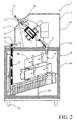
- the refrigeration and storage module 6 of substantially cubic shape, rests on the ground by feet 61 and includes a device for generating cold (not shown) conventionally comprising a compressor, an evaporator, a condenser and a recovery tank.
- This module 6 receives above it the input and disinfection module 2, thus forming a compact device.
- This input module 2 is faired by a folded sheet 20 defining on the front face a console 21.
- inlet 4 and outlet 7 of the refrigeration and storage module 6 are located substantially in the same plan and in the upper part. They cross the upper wall 61 of the insulated box 60 along substantially vertical axes.
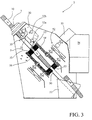
- the input and disinfection module 2 comprises a first transfer means 5 consisting of an inclined ramp 50 forming a U-shaped rail with a width substantially equivalent to that of the elements refrigerants 10.
- This inclined ramp 50 extends from the inlet 3 upper part near the inlet orifice 4, lower part, and form an acute angle, for example equal to 45 °, with the axis of this orifice 4.
- the lower end of this inclined ramp 50 comprises two lateral cheeks 51 arranged to laterally guide the cooling elements 10 when they leave the rail inclined 50 to enter the inlet 4 and pass from a position inclined to a substantially vertical position by simple gravity.
- a cleaning and disinfection device 52 On the path of the cooling elements 10, along this inclined ramp 50, a cleaning and disinfection device 52 is provided.
- This device 52 comprises, in the example shown, two circular brushes 53 arranged symmetrically with respect to the inclined ramp 50, each brush 53 being mounted on a turntable 54 driven in synchronism by a motorization 55.
- the refrigerating elements 10 move along the inclined ramp 50, on the one hand, by gravity and, on the other hand, under the effect of the brush rotation 53.
- a disinfectant liquid tank 56 is also provided for spraying said cooling elements 10 by means of a nozzle 57 whose jet is directed towards the brushes 53.
- any other mechanism cleaning and disinfection can be considered.
- the inlet 3 has a section opening equivalent to the section transverse cooling elements 10 introduced horizontally. Voluntarily, this cross section is not symmetrical with respect to the center line of the cooling elements 10 so as to orient them correctly in the device 1.
- a presence detector 30 comprising a bent finger 31, articulated and arranged so that its free end is located on the path of the cooling elements 10, as well as at least one microswitch 32a arranged to transmit a signal to the means for actuating the slide of the lifting member described below, so as to exchange the cooling elements 10.
- the finger 31 is extended by an actuating rod 33 which comes trigger microswitch 32a only when finger 31 is pushed by a cooling element 10 according to the invention and arranged in the correct meaning, that is, the forward U-shape.
- actuating rod 33 which comes trigger microswitch 32a only when finger 31 is pushed by a cooling element 10 according to the invention and arranged in the correct meaning, that is, the forward U-shape.
- other means of detection may be provided, such as for example optical detectors.
- a second microswitch 32b is also provided, arranged to transmit a signal to the motor 55 of the cleaning device 52 when a refrigerant 10 is detected.
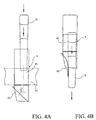
- the inlet port 4 of the refrigeration and storage module 6 has an airlock 40 of form parallelepiped mounted in a correspondingly shaped opening provided in the upper wall 61 of the insulated box 60.
- This airlock 40 exceeds on either side of this wall 61 and has a sealed door 41 disposed at its end located inside the insulated box 60.
- This door waterproof 41 is constituted by a flexible tongue, one edge of which is integral of the airlock 40 and the opposite edge closes the airlock 40 in the rest position, shown by Figure 4A.
- This flexible tongue 41 is inclined relative to the axis vertical of the airlock 40 at an acute angle, for example equal to 45 ° and is arranged for open under the weight of a cooling element 10 introduced into the airlock 40, shown in Figure 4B.
- a rail helical 80 forming the second transfer means 8 arranged for transport and store said cooling elements 10 inside the module storage and refrigeration 6.
- This helical rail 80 of flat shape and pitch constant extends inside the box from top to bottom, from its orifice inlet 4 towards the bottom of the insulated box 60.
- the turns that make up this rail helical 80 make an angle between approximately 18 ° and 25 ° with the horizontal.
- a support tube 82 is mounted in the insulated box 60 coaxially with said rail and carries spokes 83 fixed on the internal generator of the helical rail 80 for example every 90 degrees.
- the rail helical 80 is made of a metallic material and a system of defrost (not shown) can in some cases be installed inside to avoid the formation of frost
- the upper end of the helical rail 80 is straight and is located in below the inlet orifice 4 so as to receive the cooling elements 10 which fall by gravity, are positioned astride the generator upper 81 of the rail and are guided laterally by the side walls of the airlock 40 which extend on either side of said rail 80.
- the lower end of the helical rail 80 is also rectilinear to correctly position the refrigerating elements 10 relative to the third transfer means 9 which will be described below.
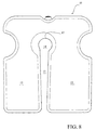
- FIG. 8 illustrates the cooling element 10, seen in plan. Its description detailed appears in the publication FR-A-2 745 933. It is presented under the shape of a substantially parallelepiped plate and comprises, in particular, a slot 11 delimiting two legs 12 and 13, this slot having a width substantially greater than the thickness of the helical rail 80 narrowing towards the bottom. This slot 11 is located under a through hole 14 where the contact zone 15 with the upper generator 81 of the helical rail 80.
- the particular construction form of the cooling elements 10 means that the center of gravity of the cooling element 10 is below this point 15 and is axially offset from the side of the widest tab 13 and the thicker of the cooling element 10 so as to balance the distribution of the substance contained in the cooling element 10 between the legs 12 and 13.
- This substance is a eutectic mixture the melting point of which is example equal to -23 ° C.
- the third transfer means 9 comprises a guide tube 90 extending inside the insulated box 60 of bottom to top, from the bottom of the insulated box to the outlet orifice 7. It defines a inner chute 91 of rectangular section whose dimensions correspond at least to the largest section of the cooling elements 10 and arranged to receive these elements in a vertical position superimposed on each other.
- the lower part of this guide tube 90 comprises a window 92 arranged perpendicular to the lower end of the rail helical 80.
- This third transfer means 9 also includes a lifting member 93 arranged to lift said cooling elements 10 superimposed inside the guide tube 90 and allow the addition of a new cooling element 10 coming from the helical rail 80 through the window 92.
- the lifting member 93 has a retractable nose 94 articulated at the end a slide 95 mounted in a support 96 arranged in parallel and at the rear of the guide tube 90.
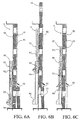
- This slide 95 is driven by a movement back-and-forth alternative translation between a low position, represented by Figures 6A and 6C, and a high position, shown in Figure 6B.
- the nose 94 is movable between two positions, an extended position, represented by FIGS. 6A and 6B, where it projects inside the guide tube 90 on the way out and a retracted position, represented by FIG. 6C, where it is retracted to inside the support 96 on the return.
- a stop 97 consisting of a rod is mounted on the slide 95 at the back of the nose 94 to limit its rotation in its extended position.
- This articulated nose 94 has a shape substantially triangular in such a way that in the extended position, its upper face is substantially horizontal and, in the retracted position, its underside is substantially vertical, the two faces defining between them an acute angle.
- the slide 95 is moved for example by a jack (not shown) or by any other equivalent means, controlled by a control unit such than a push button or a sensitive button provided in table 22 of the desk 21 or by microswitch 32a of the presence detector 30 in as part of an exchange of refrigerants 10.
- the outlet orifice 7 includes an airlock 70 passing through the upper wall 61 of the watertight box 60 right through that a watertight door 71 arranged to open under the pressure of an element refrigerant 10 pushed by the other refrigerating elements stored in the guide tube 90 and raised by the lifting member 93.
- the watertight door 71 is slidably mounted in an inclined support 72, arranged outside the watertight box 60. It has at its end closing the outlet orifice 7 a bevelled face 73 arranged to generate a backward movement of the door 71 under the effect of the thrust of the cooling element 10.
- the orifice of outlet 7 is arranged along a substantially vertical axis and the inclined support 72 forms an acute angle with the axis of this outlet orifice 7.
- the operation and use of the element dispensing device 1 10 refrigerants are particularly simple. Before the commissioning of this appliance, the refrigeration and storage module 6 is filled with elements refrigerants 10 loaded with frigories which can be stored beforehand on pallet in freezers. Through an access door (not shown), these refrigerating elements 10 can be placed directly on the helical rail 80 and in the guide tube 90.
- the button or control key sends signals to the cylinder which generates an alternative movement of the slide 95.
- position rest (fig. 6A)
- the latter In position rest (fig. 6A), the latter is in the low position.
- it When it is moved, it performs a cycle including an upward movement followed by a backward movement to return to its rest position. In his forward movement, from its low position (fig. 6A) to its high position (fig.
- the nose 94 being protruding in the guide tube 90, it raises with it the column of refrigerating elements 10 contained in this tube by bringing out the upper one through the outlet orifice 7. Simultaneously, the window 92 is clear and can receive automatically and by gravity a new element refrigerant 10 coming from the helical rail 80 (fig. 6B).
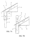
- This nose 94 is arranged so that it fits into the slot 11 of the cooling element 10 disposed in the window 92 of the guide tube 90. When lifting, the nose 94 is supported in the contact zone 15 of the through hole 14 of said cooling element 10. Its upper face is substantially horizontal to allow it to exert a lifting force in the axis of the guide tube 90.
- the extended position of this nose 94 is defined by the rod 97 which limits its rotation by forming a rear stop.
- slide 95 arrives in high position (fig. 6B), its movement is reversed and it descends in low position.
- the underside of the nose 94 abuts against the cooling elements 10 contained in the tube guide 90 and automatically causes the nose 94 to rotate in its retracted or retracted position inside the support 96 so as to disengage the nose from the guide tube 90.
- the slide 95 can, if necessary, carry out a new cycle to eject a new element refrigerant 10.
- This transfer means 9 being arranged in the module refrigeration and storage 6, the refrigerating elements 10 stored in the guide tube 90 remain at the same temperature.
- the user wants to recycle refrigerant elements discharged in frigories, it introduces them into the inlet 3 after having positioned them correctly.
- the refrigerating elements 10 descend one by one, by gravity, along the inclined ramp 50 to the outlet orifice 4.
- the presence detector 30, located behind the inlet 3 sends automatically signals to the ram of the slide 95 to realize the exchange of cooling elements 10 as well as the motor 55 which controls the cleaning and disinfection mechanism, namely the rotation of the brushes 53 and simultaneously spraying with a disinfectant liquid.
- the refrigerating elements 10 to be recycled are cleaned and disinfected before they are introduction into the refrigeration and storage module 6 through the orifice 4. This avoids any contamination with the area of refrigeration.
- the input and disinfection module 2 is completely separate and isolated from the refrigeration and storage module 6.
- the equipment electrical and electronic devices provided in this module can be standard equipment.
- the invention makes it possible to reach all the set goals and, in particular, that the particular arrangement of the two modules 2 and 6 as well as the positioning of the inlet 4 and outlet 7 ports in part height of the insulated box 60 considerably increase the refrigeration power.
Landscapes
- Physics & Mathematics (AREA)
- General Physics & Mathematics (AREA)
- Life Sciences & Earth Sciences (AREA)
- Engineering & Computer Science (AREA)
- Food Science & Technology (AREA)
- Devices That Are Associated With Refrigeration Equipment (AREA)
- Chutes (AREA)
- Stacking Of Articles And Auxiliary Devices (AREA)
- Devices For Dispensing Beverages (AREA)
- Apparatus For Disinfection Or Sterilisation (AREA)
- Gloves (AREA)
Claims (17)
- Verteilvorrichtung (1) für wiederaufladbare Kühlelemente (10), insbesondere aus Platten oder Beuteln, mit einer zur Ansammlung von Kälte formulierten Substanz, die mindestens folgendes enthält:dadurch gekennzeichnet, dassein Eingangs- und Desinfektionsmodul (2) der Kühlelemente (10), welches mit einer Eingangsöffnung (3), einer Ausgangsöffnung (4) und einer ersten Einrichtung (5) zum Transportieren der Elemente zwischen den zwei Öffnungen versehen ist, undein Modul (6) zum Kühlen und Lagern der Kühlelemente (10), welches mit einem Isolationsbehälter (60), einer Kälteerzeugungsvorrichtung versehen ist, die angeordnet ist, um die Kühlelemente mit Kälte aufzuladen, mit einer der Ausgangsöffnung des Eingangs- und Desinfektionsmoduls (2) entsprechenden Eingangsöffnung (4), einer Ausgangsöffnung (7) versehen ist, wobei die Öffnungen (4,7) eine Wand (61) des Isolationsbehälters (60) durchqueren, mit einer zweiten Transporteinrichtung (8) zum Transportieren der zu recycelnden Kühlelemente (10) in das Innere des Moduls zum Kühlen und Lagern durch Schwerkraft versehen ist,
das Eingangs- und Desinfektionsmodul (2) über dem Modul (6) zum Kühlen und Lagern angeordnet ist,
die Eingangs- (4) und Ausgangsöffnungen (7) des Moduls (6) zum Kühlen und Lagern im oberen Teil des Moduls angeordnet sind,
und dass das Modul (6) zum Kühlen und Lagern eine dritte Transporteinrichtung (9) aufweist, die angeordnet ist, um die Kühlelemente wieder zu der Ausgangsöffnung (7) hinauf zu transportieren. - Verteilvorrichtung nach Anspruch 1,
dadurch gekennzeichnet, dass
die Eingangs- (4) und Ausgangsöffnungen (7) des Moduls (6) zum Kühlen und Lagern praktisch auf derselben Ebene angeordnet sind. - Verteilvorrichtung nach Anspruch 1 oder 2,
dadurch gekennzeichnet, dass
die erste Transporteinrichtung (5) eine geneigte Rampe (50) aufweist, die angeordnet ist, um die Kühlelemente (10) durch Schwerkraft von der Eingangsöffnung (3) zu der Ausgangsöffnung (4) zu transportieren. - Verteilvorrichtung nach Anspruch 3,
dadurch gekennzeichnet, dass
das Eingangs- und Desinfektionsmodul (2) eine Reinigungsvorrichtung mit zwei Rundbürsten (53) aufweist, die im Verhältnis zu der geneigten Rampe (50) symme-trisch auf dem Weg der Kühlelemente (10) angeordnet sind, wobei jede Bürste (53) auf einer durch eine Motorisierung (55) angetriebenen Scheibe (54) angebracht ist. - Verteilvorrichtung nach Anspruch 4,
dadurch gekennzeichnet, dass
die Eingangsöffnung (3) einen Vorhandenseinsdetektor (30) aufweist, der zur Übertragung eines Signals zu der Motorisierung (55) der Reinigungsvorrichtung angeordnet ist, wenn ein Kühlelement (10) erkannt wird. - Verteilvorrichtung nach Anspruch 5,
dadurch gekennzeichnet, dass
der Vorhandenseinsdetektor (30) einen gekrümmten, gelenkig gelagerten Finger (31), der unter der Wirkung einer Rückholfeder steht, die so angeordnet ist, dass ihr freies äußerstes Ende hinter der Eingangsöffnung (3) auf dem Weg der Kühlelemente (10) angeordnet ist, und mindestens einen Mikroschalter (32) aufweist. - Verteilvorrichtung nach Anspruch 1 oder 2,
dadurch gekennzeichnet, dass
die Eingangsöffnung (4) des Moduls (6) zum Kühlen und Lagern eine dichte Tür aufweist, die aus einer nachgiebigen Lasche (41) besteht, die angeordnet ist, um sich unter dem Gewicht eines Kühlelementes (10) zu öffnen. - Verteilvorrichtung nach Anspruch 1 oder 2,
dadurch gekennzeichnet, dass
die zweite Transporteinrichtung (8) aus einer spiralförmigen Schiene (80) besteht, die sich im Inneren des Behälters von seiner Eingangsöffnung (4) in dem oberen Teil zu dem unteren Teil erstreckt,
wobei die Schiene so angeordnet ist, dass sie die Kühlelemente (10) in einer praktisch vertikalen Position aufnimmt, in welcher sie rittlings auf ihrer Oberkante (81) angeordnet sind. - Verteilvorrichtung nach den Ansprüchen 3 und 8,
dadurch gekennzeichnet, dass
die Eingangsöffnung (4) des Moduls (6) zum Lagern und Kühlen entsprechend einer praktisch vertikalen Achse angeordnet ist, und dass die geneigte Rampe (50) der ersten Transporteinrichtung (5) einen spitzen Winkel mit der Achse der Eingangsöffnung (4) bildet. - Verteilvorrichtung nach Anspruch 1,
dadurch gekennzeichnet, dass
die dritte Transporteinrichtung (9) ein Führungsrohr (90) aufweist, welches sich im Inneren des Isolationsbehälters (60) von seinem unteren Teil zu seiner Ausgangsöffnung (7) in dem oberen Teil erstreckt, und angeordnet ist, um die Kühlelemente (10) in vertikaler Position übereinanderliegend aufzunehmen, wobei der untere Teil des Führungsrohres (90) ein gegenüber dem äußersten unteren Ende der spiralförmigen Schiene (80) angeordnetes Fenster (92), sowie ein Hubelement (93) aufweist, welches angeordnet ist, um die im Inneren des Führungsrohres (90) übereinandergelagerten Kühlelemente (10) anzuheben und das Hinzufügen eines von der spiralförmigen Schiene (80) kommenden neuen Kühlelementes (10) zu ermöglichen. - Verteilvorrichtung nach den Ansprüchen 8 und 10,
dadurch gekennzeichnet, dass
das äußerste untere Ende der spiralförmigen Schiene (80) geradlinig, und praktisch senkrecht zu dem Fenster (92) des Führungsrohres (90) angeordnet ist. - Verteilvorrichtung nach Anspruch 10,
dadurch gekennzeichnet, dass
das Hubelement (93) eine umklappbare Nase (94) aufweist, die an dem äußersten Ende eines Gleitstückes (95) gelenkig gelagert ist, welches parallel und hinter dem Führungsrohr (90) in einem Träger (96) angebracht ist, wobei das Gleitstück (95) von einer wechselweisen Translations-Hin- und Herbewegung zwischen einer unteren Position und einer oberen Position angetrieben wird, und die Nase (94) zwischen zwei Positionen, d. h. zwischen einer Ausgangsposition, in welcher sie auf dem Hinweg über das Innere des Führungsrohres (90) hervorsteht, und einer Rückkehrposition bewegbar ist, in welche sie bei der Rückkehr in das Innere des Trägers (96) umgeklappt wird. - Verteilvorrichtung nach Anspruch 12,
dadurch gekennzeichnet, dass
das Hubelement (93) einen Anschlag (97) aufweist, der angeordnet ist, um die Drehung der gelenkig gelagerten Nase (94) in ihre Ausgangsposition zu begrenzen. - Verteilvorrichtung nach Anspruch 13,
dadurch gekennzeichnet, dass
die gelenkig gelagerte Nase (94) praktisch eine solche dreieckige Form aufweist, dass ihre obere Fläche in der Ausgangsposition praktisch horizontal ist, wobei ihre Innenfläche praktisch vertikal ist und die zwei Flächen zwischen sich einen spitzen Winkel festlegen. - Verteilvorrichtung nach Anspruch 10,
dadurch gekennzeichnet, dass
die Ausgangsöffnung (7) eine dichte Tür (71) aufweist, die angeordnet ist, um sich unter dem Schub eines in dem Führungsrohr (90) gelagerten Kühlelementes (10) zu öffnen. - Verteilvorrichtung nach Anspruch 15,
dadurch gekennzeichnet, dass
die dichte Tür (71) gleitend bewegbar in einem außerhalb des Isolationsbehälters (60) angeordneten, geneigten Träger (72) angebracht ist, und dass sie an ihrem die Ausgangsöffnung (7) abdeckenden äußersten Ende eine abgeschrägte Fläche (73) aufweist, die angeordnet ist, um unter der Schubwirkung des Kühlelementes (10) eine Rückzugsbewegung zu erzeugen. - Verteilvorrichtung nach Anspruch 16,
dadurch gekennzeichnet, dass
die Ausgangsöffnung (7) entsprechend einer praktisch vertikalen Achse angeordnet ist, und dass die geneigte Rampe (72) einen spitzen Winkel mit der Achse der Ausgangsöffnung bildet.
Applications Claiming Priority (3)
| Application Number | Priority Date | Filing Date | Title |
|---|---|---|---|
| FR0003934A FR2807190B1 (fr) | 2000-03-29 | 2000-03-29 | Appareil distributeur d'elements refrigerants rechargeables |
| FR0003934 | 2000-03-29 | ||
| PCT/IB2001/000517 WO2001073703A1 (fr) | 2000-03-29 | 2001-03-29 | Appareil distributeur d'elements refrigerants rechargeables |
Publications (2)
| Publication Number | Publication Date |
|---|---|
| EP1269432A1 EP1269432A1 (de) | 2003-01-02 |
| EP1269432B1 true EP1269432B1 (de) | 2003-09-17 |
Family
ID=8848590
Family Applications (1)
| Application Number | Title | Priority Date | Filing Date |
|---|---|---|---|
| EP01914133A Expired - Lifetime EP1269432B1 (de) | 2000-03-29 | 2001-03-29 | Ausgabeautomat für wideraufladbare kühlelemente |
Country Status (15)
| Country | Link |
|---|---|
| US (1) | US6755320B2 (de) |
| EP (1) | EP1269432B1 (de) |
| JP (1) | JP4666870B2 (de) |
| CN (1) | CN1161717C (de) |
| AT (1) | ATE250258T1 (de) |
| AU (1) | AU3950901A (de) |
| BR (1) | BRPI0109652B1 (de) |
| CA (1) | CA2404637C (de) |
| DE (1) | DE60100805T2 (de) |
| DK (1) | DK1269432T3 (de) |
| ES (1) | ES2208572T3 (de) |
| FR (1) | FR2807190B1 (de) |
| PT (1) | PT1269432E (de) |
| TR (1) | TR200302191T4 (de) |
| WO (1) | WO2001073703A1 (de) |
Families Citing this family (9)
| Publication number | Priority date | Publication date | Assignee | Title |
|---|---|---|---|---|
| FR2871272B1 (fr) * | 2004-06-04 | 2006-08-18 | Cool Sarl Sarl Soc | Procede et appareillage pour effectuer une distribution individuelle d'espaces fermes froids destines a garder au froid des denrees alimentaires ou des substances medicamenteuses ou equivalentes |
| ITBS20110082A1 (it) * | 2011-06-01 | 2012-12-02 | Luigi Faglia | Dispositivo di erogazione a lancio di prodotti da un distributore automatico |
| USD691207S1 (en) * | 2012-02-20 | 2013-10-08 | Societe Des Produits Nestle S.A. | Beverage machine support |
| FR2992406A1 (fr) * | 2012-06-26 | 2013-12-27 | Futurinov | Distributeur passif d'accumulateurs de froid et accumulateur de froid associe |
| US20170061725A1 (en) * | 2015-09-02 | 2017-03-02 | Sherry J. Cerny | Frozen Freezer Pack |
| US11282326B2 (en) * | 2018-11-02 | 2022-03-22 | Pepsico, Inc. | Table vending machine |
| CN113531970A (zh) * | 2021-07-12 | 2021-10-22 | 青岛澳柯玛生物医疗有限公司 | 一种注射剂保存箱及其控制系统和使用方法 |
| CN115973804A (zh) * | 2022-07-22 | 2023-04-18 | 离享未来(天津)科技有限公司 | 一种智能无人化装卸冷链集装箱的实现方法 |
| DE102023104629A1 (de) * | 2023-02-24 | 2024-08-29 | Viessmann Refrigeration Solutions Gmbh | Regenerationsmagazin zur aktiven Regeneration von entladenen Temperierelementen |
Family Cites Families (8)
| Publication number | Priority date | Publication date | Assignee | Title |
|---|---|---|---|---|
| US2232619A (en) * | 1939-12-27 | 1941-02-18 | Allen G Maccartee | Bottle dispenser |
| JPS475617Y1 (de) * | 1967-10-05 | 1972-02-28 | ||
| FR2258672A1 (en) * | 1974-01-17 | 1975-08-18 | Levi Henri | Coin-operated distributor for refrigerated containers - has refrigerated vertical container stack above extract drawer |
| FR2258671A1 (en) | 1974-01-18 | 1975-08-18 | Sedatom | Monitoring device for internal heart pacemaker - has inductive circuit detecting pacemaker pulses and loudspeaker |
| DE3215627A1 (de) * | 1982-04-27 | 1983-11-03 | Paul Hettler | Kuehlbomben-umlaufsystem mit verkaufs-automatisation |
| EP0140153A3 (en) * | 1983-10-27 | 1986-07-30 | Gyorgy Teglasy | Coin-operated apparatus for dispensing cooling elements |
| DE9303765U1 (de) * | 1993-03-15 | 1993-05-13 | Heide, Karin, Dipl.-Designerin, 7000 Stuttgart | Becherspend- und -spülautomat einschließlich zugehörigem Trinkgefäß |
| FR2745933B1 (fr) * | 1996-03-11 | 1998-06-12 | Alvaro Gonzalez | Appareil distributeur d'elements refrigerants et lesdits elements refrigerants |
-
2000
- 2000-03-29 FR FR0003934A patent/FR2807190B1/fr not_active Expired - Fee Related
-
2001
- 2001-03-29 US US10/239,935 patent/US6755320B2/en not_active Expired - Lifetime
- 2001-03-29 DE DE60100805T patent/DE60100805T2/de not_active Expired - Lifetime
- 2001-03-29 CA CA002404637A patent/CA2404637C/fr not_active Expired - Lifetime
- 2001-03-29 DK DK01914133T patent/DK1269432T3/da active
- 2001-03-29 WO PCT/IB2001/000517 patent/WO2001073703A1/fr not_active Ceased
- 2001-03-29 CN CNB018074138A patent/CN1161717C/zh not_active Expired - Fee Related
- 2001-03-29 AT AT01914133T patent/ATE250258T1/de active
- 2001-03-29 TR TR2003/02191T patent/TR200302191T4/xx unknown
- 2001-03-29 JP JP2001571346A patent/JP4666870B2/ja not_active Expired - Fee Related
- 2001-03-29 AU AU39509/01A patent/AU3950901A/en not_active Abandoned
- 2001-03-29 ES ES01914133T patent/ES2208572T3/es not_active Expired - Lifetime
- 2001-03-29 PT PT01914133T patent/PT1269432E/pt unknown
- 2001-03-29 EP EP01914133A patent/EP1269432B1/de not_active Expired - Lifetime
- 2001-03-29 BR BRPI0109652A patent/BRPI0109652B1/pt not_active IP Right Cessation
Also Published As
| Publication number | Publication date |
|---|---|
| BRPI0109652B1 (pt) | 2016-02-23 |
| CA2404637C (fr) | 2009-01-06 |
| PT1269432E (pt) | 2004-02-27 |
| FR2807190A1 (fr) | 2001-10-05 |
| AU3950901A (en) | 2001-10-08 |
| ES2208572T3 (es) | 2004-06-16 |
| US20030089729A1 (en) | 2003-05-15 |
| JP2003529042A (ja) | 2003-09-30 |
| DE60100805D1 (de) | 2003-10-23 |
| BR0109652A (pt) | 2003-04-22 |
| EP1269432A1 (de) | 2003-01-02 |
| CN1421025A (zh) | 2003-05-28 |
| CN1161717C (zh) | 2004-08-11 |
| FR2807190B1 (fr) | 2002-06-28 |
| WO2001073703A1 (fr) | 2001-10-04 |
| DK1269432T3 (da) | 2004-01-26 |
| CA2404637A1 (fr) | 2001-10-04 |
| JP4666870B2 (ja) | 2011-04-06 |
| US6755320B2 (en) | 2004-06-29 |
| DE60100805T2 (de) | 2004-07-15 |
| TR200302191T4 (tr) | 2004-02-23 |
| ATE250258T1 (de) | 2003-10-15 |
Similar Documents
| Publication | Publication Date | Title |
|---|---|---|
| EP0824739B1 (de) | Ausgabeautomat für kühlelemente und entsprechende kühlelemente | |
| CA2404637C (fr) | Appareil distributeur d'elements refrigerants rechargeables | |
| EP1176402A1 (de) | Dosiervorrichtung und Spender mit einer solchen Vorrichtung | |
| EP1730708B1 (de) | Automatischer spender für voluminöse und/oder schwere produkte und/oder produkte in paketen | |
| FR2987761A1 (fr) | Dispositif de distribution de parfum sur une bande de papier. | |
| FR2749960A1 (fr) | Distributeur automatique de fleurs fraiches coupees confectionnant des bouquets a la demande | |
| FR2600991A1 (fr) | Distributeur d'elements minces empiles, muni d'un dispositif d'extraction de ces derniers, et boite-cartouche d'elements minces susceptible d'equiper un tel distributeur | |
| FR2760826A1 (fr) | Chariot refrigere et installation de rechargement en agent refrigerant | |
| FR3053819B1 (fr) | Distributeur automatique a dispositif de recuperation mobile | |
| WO2002028763A1 (fr) | Distributeur de boisson refrigeree equipe de deux moyens refrigerants | |
| WO2013059237A1 (en) | Collapsible containers, collapsible container dispensers, and methods of dispensing a collapsible container | |
| WO1987000664A1 (fr) | Dispositif de distribution et de vente de supports souples | |
| EP0759008B1 (de) | Flüssigkeitsspender | |
| EP0698260A1 (de) | Automatisches ausgabelager | |
| FR2872614A1 (fr) | Appareil de distribution automatique de produits volumineux et/ou lourds et/ou vendus en pack | |
| FR2854450A1 (fr) | Dispositif d'installation de refroidissement utilise dans le domaine de l'elaboration des vins selon la methode dite champenoise | |
| FR3098212A1 (fr) | Appareil de distribution d’un produit contenu dans une poche de stockage | |
| FR2835045A1 (fr) | Dispositif pour la conservation au frais de produits divers | |
| WO2007028878A2 (fr) | Dispositif de refrigeration | |
| FR2866968A1 (fr) | Appareil de distribution automatique de produits volumineux et/ou lourds et/ou vendus en packs | |
| FR3131285A1 (fr) | Installation de distribution de boissons dans des recipients notamment de type canette | |
| FR2565336A1 (fr) | Machine de production de neige carbonique | |
| WO2006042963A1 (fr) | Dispositif de compactage et vidage de cannettes pour boisson | |
| EP0436446A1 (de) | Vorrichtung zur Rücknahme und Zerstören eines Kunststoff-Gegenstandes gegen Ausgabe eines Gegenwertes | |
| FR2591879A3 (fr) | Installation de conservation au chaud d'assiettes sur chariot de stockage deconnectable d'un generateur de diffusion d'air chaud pulse |
Legal Events
| Date | Code | Title | Description |
|---|---|---|---|
| PUAI | Public reference made under article 153(3) epc to a published international application that has entered the european phase |
Free format text: ORIGINAL CODE: 0009012 |
|
| AK | Designated contracting states |
Kind code of ref document: A1 Designated state(s): AT BE CH CY DE DK ES FI FR GB GR IE IT LI LU MC NL PT SE TR |
|
| AX | Request for extension of the european patent |
Free format text: AL;LT;LV;MK;RO;SI |
|
| 17P | Request for examination filed |
Effective date: 20021029 |
|
| GRAH | Despatch of communication of intention to grant a patent |
Free format text: ORIGINAL CODE: EPIDOS IGRA |
|
| GRAS | Grant fee paid |
Free format text: ORIGINAL CODE: EPIDOSNIGR3 |
|
| GRAA | (expected) grant |
Free format text: ORIGINAL CODE: 0009210 |
|
| AK | Designated contracting states |
Kind code of ref document: B1 Designated state(s): AT BE CH CY DE DK ES FI FR GB GR IE IT LI LU MC NL PT SE TR |
|
| PG25 | Lapsed in a contracting state [announced via postgrant information from national office to epo] |
Ref country code: CY Free format text: LAPSE BECAUSE OF FAILURE TO SUBMIT A TRANSLATION OF THE DESCRIPTION OR TO PAY THE FEE WITHIN THE PRESCRIBED TIME-LIMIT Effective date: 20030917 |
|
| REG | Reference to a national code |
Ref country code: GB Ref legal event code: FG4D Free format text: NOT ENGLISH |
|
| REG | Reference to a national code |
Ref country code: CH Ref legal event code: EP |
|
| REF | Corresponds to: |
Ref document number: 60100805 Country of ref document: DE Date of ref document: 20031023 Kind code of ref document: P |
|
| REG | Reference to a national code |
Ref country code: IE Ref legal event code: FG4D Free format text: FRENCH |
|
| REG | Reference to a national code |
Ref country code: SE Ref legal event code: TRGR |
|
| REG | Reference to a national code |
Ref country code: CH Ref legal event code: NV Representative=s name: CABINET ROLAND NITHARDT CONSEILS EN PROPRIETE INDU |
|
| REG | Reference to a national code |
Ref country code: DK Ref legal event code: T3 |
|
| REG | Reference to a national code |
Ref country code: GR Ref legal event code: EP Ref document number: 20030405142 Country of ref document: GR |
|
| GBT | Gb: translation of ep patent filed (gb section 77(6)(a)/1977) |
Effective date: 20040112 |
|
| LTIE | Lt: invalidation of european patent or patent extension |
Effective date: 20030917 |
|
| PG25 | Lapsed in a contracting state [announced via postgrant information from national office to epo] |
Ref country code: MC Free format text: LAPSE BECAUSE OF NON-PAYMENT OF DUE FEES Effective date: 20040331 |
|
| REG | Reference to a national code |
Ref country code: ES Ref legal event code: FG2A Ref document number: 2208572 Country of ref document: ES Kind code of ref document: T3 |
|
| PLBE | No opposition filed within time limit |
Free format text: ORIGINAL CODE: 0009261 |
|
| STAA | Information on the status of an ep patent application or granted ep patent |
Free format text: STATUS: NO OPPOSITION FILED WITHIN TIME LIMIT |
|
| 26N | No opposition filed |
Effective date: 20040618 |
|
| REG | Reference to a national code |
Ref country code: CH Ref legal event code: PUE Owner name: TECHNI-LOISIRS Free format text: INTERNOVA INTERNATIONAL INNOVATION COMPANY B.V.#AERT VAN NESSTRAAT 45#3012 CA ROTTERDAM (NL) -TRANSFER TO- TECHNI-LOISIRS#10, RUE ISAAC NEWTON Z.I. DU COUDRAY#93155 LE BLANC-MESNIL (FR) |
|
| REG | Reference to a national code |
Ref country code: GB Ref legal event code: 732E |
|
| REG | Reference to a national code |
Ref country code: FR Ref legal event code: TP |
|
| NLS | Nl: assignments of ep-patents |
Owner name: TECHNI LOISIRS Effective date: 20060503 |
|
| PG25 | Lapsed in a contracting state [announced via postgrant information from national office to epo] |
Ref country code: TR Free format text: LAPSE BECAUSE OF FAILURE TO SUBMIT A TRANSLATION OF THE DESCRIPTION OR TO PAY THE FEE WITHIN THE PRESCRIBED TIME-LIMIT Effective date: 20030917 |
|
| PGFP | Annual fee paid to national office [announced via postgrant information from national office to epo] |
Ref country code: TR Payment date: 20110309 Year of fee payment: 11 |
|
| REG | Reference to a national code |
Ref country code: CH Ref legal event code: PFA Owner name: FRIODIS, FR Free format text: FORMER OWNER: TECHNI-LOISIRS, FR |
|
| REG | Reference to a national code |
Ref country code: DE Ref legal event code: R082 Ref document number: 60100805 Country of ref document: DE Representative=s name: LORENZ & KOLLEGEN PATENTANWAELTE PARTNERSCHAFT, DE Effective date: 20130219 Ref country code: DE Ref legal event code: R081 Ref document number: 60100805 Country of ref document: DE Owner name: FRIODIS S. A., FR Free format text: FORMER OWNER: TECHNI- LOISIRS, LE BLOANC MESNIL, FR Effective date: 20130219 |
|
| REG | Reference to a national code |
Ref country code: FR Ref legal event code: CD Owner name: FRIODIS, FR Effective date: 20130422 |
|
| REG | Reference to a national code |
Ref country code: FR Ref legal event code: PLFP Year of fee payment: 16 |
|
| REG | Reference to a national code |
Ref country code: FR Ref legal event code: PLFP Year of fee payment: 17 |
|
| REG | Reference to a national code |
Ref country code: FR Ref legal event code: PLFP Year of fee payment: 18 |
|
| REG | Reference to a national code |
Ref country code: CH Ref legal event code: NV Representative=s name: ACTOSPHERE SARL, CH Ref country code: CH Ref legal event code: PFA Owner name: FRIODIS S.A., FR Free format text: FORMER OWNER: FRIODIS, FR |
|
| PGFP | Annual fee paid to national office [announced via postgrant information from national office to epo] |
Ref country code: LU Payment date: 20190326 Year of fee payment: 19 Ref country code: FI Payment date: 20190314 Year of fee payment: 19 |
|
| PGFP | Annual fee paid to national office [announced via postgrant information from national office to epo] |
Ref country code: GB Payment date: 20190218 Year of fee payment: 6 Ref country code: DK Payment date: 20190319 Year of fee payment: 19 |
|
| PGFP | Annual fee paid to national office [announced via postgrant information from national office to epo] |
Ref country code: ES Payment date: 20190528 Year of fee payment: 19 Ref country code: PT Payment date: 20190311 Year of fee payment: 19 |
|
| PGFP | Annual fee paid to national office [announced via postgrant information from national office to epo] |
Ref country code: CH Payment date: 20190620 Year of fee payment: 19 |
|
| PGFP | Annual fee paid to national office [announced via postgrant information from national office to epo] |
Ref country code: AT Payment date: 20200311 Year of fee payment: 20 Ref country code: GR Payment date: 20200316 Year of fee payment: 20 Ref country code: IT Payment date: 20200302 Year of fee payment: 20 |
|
| PGFP | Annual fee paid to national office [announced via postgrant information from national office to epo] |
Ref country code: BE Payment date: 20200313 Year of fee payment: 20 |
|
| PGFP | Annual fee paid to national office [announced via postgrant information from national office to epo] |
Ref country code: FR Payment date: 20200323 Year of fee payment: 20 |
|
| PGFP | Annual fee paid to national office [announced via postgrant information from national office to epo] |
Ref country code: DE Payment date: 20200409 Year of fee payment: 20 |
|
| REG | Reference to a national code |
Ref country code: FI Ref legal event code: MAE |
|
| PG25 | Lapsed in a contracting state [announced via postgrant information from national office to epo] |
Ref country code: PT Free format text: LAPSE BECAUSE OF NON-PAYMENT OF DUE FEES Effective date: 20200929 Ref country code: FI Free format text: LAPSE BECAUSE OF NON-PAYMENT OF DUE FEES Effective date: 20200329 |
|
| REG | Reference to a national code |
Ref country code: CH Ref legal event code: PL |
|
| REG | Reference to a national code |
Ref country code: DK Ref legal event code: EBP Effective date: 20200331 |
|
| REG | Reference to a national code |
Ref country code: NL Ref legal event code: MM Effective date: 20200401 |
|
| PG25 | Lapsed in a contracting state [announced via postgrant information from national office to epo] |
Ref country code: NL Free format text: LAPSE BECAUSE OF NON-PAYMENT OF DUE FEES Effective date: 20200401 Ref country code: LU Free format text: LAPSE BECAUSE OF NON-PAYMENT OF DUE FEES Effective date: 20200329 |
|
| PG25 | Lapsed in a contracting state [announced via postgrant information from national office to epo] |
Ref country code: SE Free format text: LAPSE BECAUSE OF NON-PAYMENT OF DUE FEES Effective date: 20200330 Ref country code: CH Free format text: LAPSE BECAUSE OF NON-PAYMENT OF DUE FEES Effective date: 20200331 Ref country code: IE Free format text: LAPSE BECAUSE OF NON-PAYMENT OF DUE FEES Effective date: 20200329 Ref country code: LI Free format text: LAPSE BECAUSE OF NON-PAYMENT OF DUE FEES Effective date: 20200331 |
|
| REG | Reference to a national code |
Ref country code: DE Ref legal event code: R071 Ref document number: 60100805 Country of ref document: DE |
|
| GBPC | Gb: european patent ceased through non-payment of renewal fee |
Effective date: 20200329 |
|
| PG25 | Lapsed in a contracting state [announced via postgrant information from national office to epo] |
Ref country code: GB Free format text: LAPSE BECAUSE OF NON-PAYMENT OF DUE FEES Effective date: 20200329 Ref country code: DK Free format text: LAPSE BECAUSE OF NON-PAYMENT OF DUE FEES Effective date: 20200331 |
|
| REG | Reference to a national code |
Ref country code: BE Ref legal event code: MK Effective date: 20210329 |
|
| REG | Reference to a national code |
Ref country code: AT Ref legal event code: MK07 Ref document number: 250258 Country of ref document: AT Kind code of ref document: T Effective date: 20210329 |
|
| PG25 | Lapsed in a contracting state [announced via postgrant information from national office to epo] |
Ref country code: PT Free format text: LAPSE BECAUSE OF EXPIRATION OF PROTECTION Effective date: 20210408 |
|
| REG | Reference to a national code |
Ref country code: ES Ref legal event code: FD2A Effective date: 20210806 |
|
| PG25 | Lapsed in a contracting state [announced via postgrant information from national office to epo] |
Ref country code: ES Free format text: LAPSE BECAUSE OF NON-PAYMENT OF DUE FEES Effective date: 20200330 |
|
| PG25 | Lapsed in a contracting state [announced via postgrant information from national office to epo] |
Ref country code: TR Free format text: LAPSE BECAUSE OF NON-PAYMENT OF DUE FEES Effective date: 20200329 |
|
| PG25 | Lapsed in a contracting state [announced via postgrant information from national office to epo] |
Ref country code: PT Free format text: LAPSE BECAUSE OF NON-PAYMENT OF DUE FEES Effective date: 20200504 |
|
| PG25 | Lapsed in a contracting state [announced via postgrant information from national office to epo] |
Ref country code: PT Free format text: LAPSE BECAUSE OF NON-PAYMENT OF DUE FEES Effective date: 20200504 |