EP0824965A2 - Machine à déchiqueter le bois en copeaux - Google Patents
Machine à déchiqueter le bois en copeaux Download PDFInfo
- Publication number
- EP0824965A2 EP0824965A2 EP97306175A EP97306175A EP0824965A2 EP 0824965 A2 EP0824965 A2 EP 0824965A2 EP 97306175 A EP97306175 A EP 97306175A EP 97306175 A EP97306175 A EP 97306175A EP 0824965 A2 EP0824965 A2 EP 0824965A2
- Authority
- EP
- European Patent Office
- Prior art keywords
- cutters
- machine
- flywheel
- cutter
- blade
- Prior art date
- Legal status (The legal status is an assumption and is not a legal conclusion. Google has not performed a legal analysis and makes no representation as to the accuracy of the status listed.)
- Withdrawn
Links
- 239000002023 wood Substances 0.000 title description 2
- 239000000463 material Substances 0.000 abstract description 9
- 230000000694 effects Effects 0.000 description 4
- 229910000831 Steel Inorganic materials 0.000 description 1
- 239000011093 chipboard Substances 0.000 description 1
- 239000002361 compost Substances 0.000 description 1
- 239000002826 coolant Substances 0.000 description 1
- 230000002349 favourable effect Effects 0.000 description 1
- 239000002828 fuel tank Substances 0.000 description 1
- 238000004519 manufacturing process Methods 0.000 description 1
- 239000011236 particulate material Substances 0.000 description 1
- 238000004904 shortening Methods 0.000 description 1
- 239000010959 steel Substances 0.000 description 1
- 239000002699 waste material Substances 0.000 description 1
Images

Classifications
-
- B—PERFORMING OPERATIONS; TRANSPORTING
- B27—WORKING OR PRESERVING WOOD OR SIMILAR MATERIAL; NAILING OR STAPLING MACHINES IN GENERAL
- B27L—REMOVING BARK OR VESTIGES OF BRANCHES; SPLITTING WOOD; MANUFACTURE OF VENEER, WOODEN STICKS, WOOD SHAVINGS, WOOD FIBRES OR WOOD POWDER
- B27L11/00—Manufacture of wood shavings, chips, powder, or the like; Tools therefor
- B27L11/005—Tools therefor
-
- B—PERFORMING OPERATIONS; TRANSPORTING
- B02—CRUSHING, PULVERISING, OR DISINTEGRATING; PREPARATORY TREATMENT OF GRAIN FOR MILLING
- B02C—CRUSHING, PULVERISING, OR DISINTEGRATING IN GENERAL; MILLING GRAIN
- B02C18/00—Disintegrating by knives or other cutting or tearing members which chop material into fragments
- B02C18/06—Disintegrating by knives or other cutting or tearing members which chop material into fragments with rotating knives
- B02C18/14—Disintegrating by knives or other cutting or tearing members which chop material into fragments with rotating knives within horizontal containers
- B02C18/143—Disintegrating by knives or other cutting or tearing members which chop material into fragments with rotating knives within horizontal containers with a disc rotor having generally radially extending slots or openings bordered with cutting knives
-
- B—PERFORMING OPERATIONS; TRANSPORTING
- B02—CRUSHING, PULVERISING, OR DISINTEGRATING; PREPARATORY TREATMENT OF GRAIN FOR MILLING
- B02C—CRUSHING, PULVERISING, OR DISINTEGRATING IN GENERAL; MILLING GRAIN
- B02C18/00—Disintegrating by knives or other cutting or tearing members which chop material into fragments
- B02C18/06—Disintegrating by knives or other cutting or tearing members which chop material into fragments with rotating knives
- B02C18/16—Details
- B02C18/18—Knives; Mountings thereof
-
- B—PERFORMING OPERATIONS; TRANSPORTING
- B02—CRUSHING, PULVERISING, OR DISINTEGRATING; PREPARATORY TREATMENT OF GRAIN FOR MILLING
- B02C—CRUSHING, PULVERISING, OR DISINTEGRATING IN GENERAL; MILLING GRAIN
- B02C2201/00—Codes relating to disintegrating devices adapted for specific materials
- B02C2201/06—Codes relating to disintegrating devices adapted for specific materials for garbage, waste or sewage
- B02C2201/066—Codes relating to disintegrating devices adapted for specific materials for garbage, waste or sewage for garden waste
Definitions
- This invention relates to machines for making chips from brushwood and the like. These are used by tree surgeons, contractors, and public authorities to clear waste timber and turn it into a particulate material useful for mulching ,compost production and possibly, also as a material for making wood-based products such as chip-board.
- the industry standard machine has a feed roller or rollers provided with teeth to grip and embed in the branches, small diameter logs, twigs and the like, and feed these through a throat to meet a flywheel generally normally and at a radial position relative to its centre.
- the flywheel is massive, because of the requirements and carries cutter blades on one face at a plurality of radial locations, typically three, each of which is a straight blade which has its cutting edge extending parallel to an individual radius of the flywheel and of a length corresponding to a particular dimension of the throat.
- One edge of the throat provides a second cutting edge. As each blade moves over the throat and across the second cutting edge, the end of the fed material which projects beyond that edge is impacted by the blade and chopped off. Because of the nature of the material with a grain structure, a large area, as of a log, is fractured into a large number of chips. Small cross-sectional areas such as twigs may form only a single chip with each cutting stroke.
- the flywheel may rotate at a high speed of the order of hundreds or thousands of RPM, and there is considerable noise from the cutters operation as well as from the driving source.
- the blade life is relatively short between each re-sharpening operation or replacement, due to ordinary wear and tear, and to foreign bodies which tend to be fed in, e.g. stones or grit.
- a chipper run more-or-less continuously during working shifts may need sharpening every say 15-30 hours, and can be re-sharpened a limited number of times.
- the object of the invention is to provide improvements, particularly in shortening down time when sharpening is called for; in reducing cost of re-sharpening, and the cost of replacement blades.
- Supplementary objects include reducing noise, and reducing power requirements.
- a chip-making machine has blades at a plurality of generally radial positions on a flywheel and is characterised by each blade consisting of one or more individual cutters arranged so as to be angularly adjustable whereby different positions of the periphery of each cutter may be successively moved into operative position.
- a series of circular cutters is arranged along a line containing the axis of all of the plurality, possibly but not essentially with all of the cutters in point-to-point contact one with the next.
- square, or other polygonal cutters could be used in similar manner, preferably adjusted so that their combined operative edges do not form a straight line.
- the present inventor has discovered that the industry standard machine has the effect of displacing the fed material laterally of the throat in the direction from the centre of the disc to the periphery. This results in increased wear at the outer end of each of the straight-edge cutter blades used in this prior art, and perhaps increased power requirement because of less favourable mechanical advantage.
- the invention may use blades having their axes distributed along the length of an arc (ie the line containing the axes is not straight), which may include the flywheel centre, but which has the effect of displacing the fed material inwardly towards the axis of the flywheel.
- This important feature of the invention is believed to result in reduced power requirements because of improved mechanical advantage.
- An experimental machine according to the invention is substantially less noisy than existing prior art machines, possible due to the same feature.
- a saving in blade sharpening is possible, using a plurality of cutters to correspond to each of the straight cutter blades in the prior art, because the cutter nearest the flywheel axis which performs most of the cutting, due to the feature explained above, can be re-sharpened, or if necessary replaced without it being necessary to replace or resharpen the others.
- the same effect was not true in the prior art because the single blade had to be removed, and because sharpening had to be done in a jig, the whole of the length of the cutting edge had to be treated even if damage was limited to one end section.
- each cutter has a minor portion of its periphery exposed for cutting.
- each cutter has three portions which can be used in turn, before any re-sharpening is necessary.
- the cutters may each be made integral with a large diameter hub, received in a corresponding mounting socket on the flywheel, so that stresses are taken by the hub/socket engagement. Each blade may be held in position by a corresponding bolt. When blade edge replacement is necessary, the cutters may be loosened, and turned angularly to present a fresh portion of the cutting edge for use; it will be appreciated that re-sharpening is only necessary after the whole periphery has become worn. Moreover, if one cutter wears more rapidly, it may be adjusted or replaced without having to adjust or replace the unworn ones. It is believed that this feature will substantially reduce down-time, and sharpening and blade replacement costs.
- a plurality of circular cutting blades which together form a group for moving as one over the throat of the machine, is that they combine to provide an edge which may be sinuous, instead of a straight line, and moreover which can be effectively continuous (if the discs touch each other) or discontinuous (if spaced further apart) and it is thought that these factors contribute to produce a slicing action rather than a chopping action; this has some effect on power requirement, noise, and perhaps also on blade wear.
- the machine according to the present invention may be conventional in all respects except that of using the novel cutter blades arrangement.
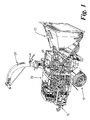
- the machine may be portable, that is to say generally arranged as a trailer to be towed by a motor vehicle by means of a towing hitch 10 and supported by a pair of wheels 12.
- the trailer supports an engine 20 with associated fuel tank coolant reservoir and like accessories.
- the engine drives a main shaft not clearly seen in FIG.1.
- the machine has a supply hopper 22, for material to be chipped. Chipped material is to be delivered through the outlet pipe 26 which can be swivelled to an appropriate angle according to the location of a skip or other receptacle for the chips.
- the flywheel 30 is made of thick steel plate and reinforced by a number of radially extended webs 32 which have the additional function of providing an air draught for carrying chipped material through the casing of the machine and through the delivery tube 26.
- the flywheel is, in this embodiment, provided with the sets of cutters which are equispaced in the interests of balance of the rotating mass afforded by the flywheel 30 and the cutters.
- Each set comprises a carrier pad 34 which may be for example welded to the flywheel 30 about its periphery, and located closely adjacent to a correspondence aperture 36 in the flywheel.
- three cutters 38, 40, 42 are provided in each set, the cutters being supported on the corresponding pad by bolts (not shown) extending through the pad and locked in place with the corresponding nuts.
- Each cutter in this embodiment is frusto-conical in shape with the larger diameter of the frusto-cone lying in a plane approximately parallel to the face of the pad and forming a cutting edge.
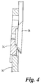
- the pad is preferably inclined to a radius of the flywheel at a small angle, typically 3 degrees, as shown in FIG.4.
- the flywheel 30 is supported on drive shaft 40 for rotation so as to take the cutters in turn past a throat (aperture) in a stationary plate 44 which is generally parallel to the plane of the flywheel forming part of the housing in which the flywheel rotates.
- a pair of spiked or similar drive rollers 46 are used to feed brushwood so that it passes through the throat and is impacted by the cutters to form chips, which are carried by the draught of air, created by the rotating vanes 32, out of the machine.
Landscapes
- Engineering & Computer Science (AREA)
- Life Sciences & Earth Sciences (AREA)
- Food Science & Technology (AREA)
- Manufacturing & Machinery (AREA)
- Mechanical Engineering (AREA)
- Wood Science & Technology (AREA)
- Forests & Forestry (AREA)
- Crushing And Pulverization Processes (AREA)
- Debarking, Splitting, And Disintegration Of Timber (AREA)
- Chemical And Physical Treatments For Wood And The Like (AREA)
- Dry Formation Of Fiberboard And The Like (AREA)
Priority Applications (1)
| Application Number | Priority Date | Filing Date | Title |
|---|---|---|---|
| EP00200057A EP1008389B1 (fr) | 1996-08-20 | 1997-08-14 | Machine à déchiqueter le bois en copeaux |
Applications Claiming Priority (2)
| Application Number | Priority Date | Filing Date | Title |
|---|---|---|---|
| GB9617458 | 1996-08-20 | ||
| GBGB9617458.6A GB9617458D0 (en) | 1996-08-20 | 1996-08-20 | Improvements in wood chipping machines |
Related Child Applications (1)
| Application Number | Title | Priority Date | Filing Date |
|---|---|---|---|
| EP00200057A Division EP1008389B1 (fr) | 1996-08-20 | 1997-08-14 | Machine à déchiqueter le bois en copeaux |
Publications (2)
| Publication Number | Publication Date |
|---|---|
| EP0824965A2 true EP0824965A2 (fr) | 1998-02-25 |
| EP0824965A3 EP0824965A3 (fr) | 1999-04-28 |
Family
ID=10798721
Family Applications (2)
| Application Number | Title | Priority Date | Filing Date |
|---|---|---|---|
| EP00200057A Expired - Lifetime EP1008389B1 (fr) | 1996-08-20 | 1997-08-14 | Machine à déchiqueter le bois en copeaux |
| EP97306175A Withdrawn EP0824965A3 (fr) | 1996-08-20 | 1997-08-14 | Machine à déchiqueter le bois en copeaux |
Family Applications Before (1)
| Application Number | Title | Priority Date | Filing Date |
|---|---|---|---|
| EP00200057A Expired - Lifetime EP1008389B1 (fr) | 1996-08-20 | 1997-08-14 | Machine à déchiqueter le bois en copeaux |
Country Status (5)
| Country | Link |
|---|---|
| US (1) | US5961057A (fr) |
| EP (2) | EP1008389B1 (fr) |
| AT (1) | ATE254966T1 (fr) |
| DE (1) | DE69726461T2 (fr) |
| GB (1) | GB9617458D0 (fr) |
Cited By (5)
| Publication number | Priority date | Publication date | Assignee | Title |
|---|---|---|---|---|
| EP0865727A3 (fr) * | 1997-03-19 | 1999-08-18 | Frielinghaus GmbH | Lame de coupe pour vis mélangeuse dans une remorque mélangeuse de fourage |
| US6082644A (en) * | 1997-08-19 | 2000-07-04 | Turner Developments, Ltd. | Shredder |
| GB2367018A (en) * | 2000-09-13 | 2002-03-27 | Wordsworth Holdings Plc | Growth shredder having cutters mounted at different radial positions |
| EP2289627A1 (fr) * | 2009-09-01 | 2011-03-02 | Turner Development Limited | Hachoir |
| CN112387388A (zh) * | 2020-10-27 | 2021-02-23 | 羊彬 | 一种粉块破碎装置 |
Families Citing this family (7)
| Publication number | Priority date | Publication date | Assignee | Title |
|---|---|---|---|---|
| US6257511B1 (en) * | 1997-08-15 | 2001-07-10 | Anthony L. Turner | Wood-chipping machines |
| US6550702B2 (en) * | 2000-02-29 | 2003-04-22 | William R Champlin | Apparatus for removing and chipping wood scraps |
| GB0130005D0 (en) * | 2001-12-14 | 2002-02-06 | Diamanx Products Ltd | Boron doped diamond |
| US7798436B2 (en) * | 2009-01-22 | 2010-09-21 | The Toro Company | Portable rotary chipper apparatus |
| DE102013202451B4 (de) * | 2013-02-14 | 2014-08-21 | Technische Universität Dresden | Vorrichtung zur Zerkleinerung von Holz mit Energiespeicher im Antriebsstrang |
| CN109249452B (zh) * | 2017-07-14 | 2024-04-02 | 惠阳亚伦塑胶电器实业有限公司 | 一种多功能切丝机 |
| CA3019727C (fr) | 2018-10-03 | 2020-02-18 | Neil K. Bramley | Ensemble de volant et palette destine a un appareil de dechiquetage et un appareil comportant ledit ensemble |
Family Cites Families (7)
| Publication number | Priority date | Publication date | Assignee | Title |
|---|---|---|---|---|
| BE543351A (fr) * | ||||
| US3266539A (en) * | 1964-03-18 | 1966-08-16 | Oliver P Gantt | Self-sharpening chipper |
| DE1528201A1 (de) * | 1966-03-24 | 1970-12-10 | Otmar Fahrion | Zerspanwerkzeug |
| DE3042950A1 (de) * | 1980-11-14 | 1982-07-01 | Crones & Co oHG, Kaltpreßwerk Ansbach, 8800 Ansbach | Umlaufend antreibbare messertraegerscheibe fuer gartenabfall-zerkleinerungsgeraete |
| US4669516A (en) * | 1985-11-18 | 1987-06-02 | Duratech, Inc. | V-shaped chipper knife |
| US5211688A (en) * | 1990-12-21 | 1993-05-18 | University Of Georgia Research Foundation, Inc. | Apparatus and method for making wood curls |
| DE9204176U1 (de) * | 1992-03-27 | 1992-05-14 | Reinbold Maschinen- und Apparatebau GmbH, 7830 Emmendingen | Vorrichtung zum Zerkleinern von Holzstücken, insbesondere von Restholz |
-
1996
- 1996-08-20 GB GBGB9617458.6A patent/GB9617458D0/en active Pending
-
1997
- 1997-08-14 DE DE69726461T patent/DE69726461T2/de not_active Expired - Lifetime
- 1997-08-14 AT AT00200057T patent/ATE254966T1/de not_active IP Right Cessation
- 1997-08-14 EP EP00200057A patent/EP1008389B1/fr not_active Expired - Lifetime
- 1997-08-14 EP EP97306175A patent/EP0824965A3/fr not_active Withdrawn
- 1997-08-15 US US08/912,085 patent/US5961057A/en not_active Expired - Fee Related
Cited By (6)
| Publication number | Priority date | Publication date | Assignee | Title |
|---|---|---|---|---|
| EP0865727A3 (fr) * | 1997-03-19 | 1999-08-18 | Frielinghaus GmbH | Lame de coupe pour vis mélangeuse dans une remorque mélangeuse de fourage |
| US6082644A (en) * | 1997-08-19 | 2000-07-04 | Turner Developments, Ltd. | Shredder |
| GB2367018A (en) * | 2000-09-13 | 2002-03-27 | Wordsworth Holdings Plc | Growth shredder having cutters mounted at different radial positions |
| GB2367018B (en) * | 2000-09-13 | 2004-07-28 | Wordsworth Holdings Plc | Growth cutters |
| EP2289627A1 (fr) * | 2009-09-01 | 2011-03-02 | Turner Development Limited | Hachoir |
| CN112387388A (zh) * | 2020-10-27 | 2021-02-23 | 羊彬 | 一种粉块破碎装置 |
Also Published As
| Publication number | Publication date |
|---|---|
| DE69726461D1 (de) | 2004-01-08 |
| EP0824965A3 (fr) | 1999-04-28 |
| EP1008389B1 (fr) | 2003-11-26 |
| EP1008389A1 (fr) | 2000-06-14 |
| US5961057A (en) | 1999-10-05 |
| GB9617458D0 (en) | 1996-10-02 |
| DE69726461T2 (de) | 2004-09-09 |
| ATE254966T1 (de) | 2003-12-15 |
Similar Documents
| Publication | Publication Date | Title |
|---|---|---|
| US6299082B1 (en) | Waste processing machine | |
| US2869793A (en) | Machine for punching and cutting of wood | |
| US6257511B1 (en) | Wood-chipping machines | |
| US4958775A (en) | Grate knife for use with winged cutting knife for producing wood chips or flakes | |
| US5372316A (en) | Waste processing machine | |
| US5419502A (en) | Tub grinder systems and methods for comminuting waste wood | |
| US5362004A (en) | Waste processing machine | |
| US5961057A (en) | Wood chipping machines | |
| US4785860A (en) | Wood processing machine having annular rings | |
| US4736781A (en) | Stump disintegrator | |
| US4773600A (en) | Stumpit | |
| US5873397A (en) | Wood pulverizer with improved hammers and anvils | |
| US6082644A (en) | Shredder | |
| US4463907A (en) | Cutter wheel for brush chipper | |
| US11084043B2 (en) | Impact cutter blade and holder system and method | |
| US4874024A (en) | Wood processing device having self-reversing feature | |
| US4776375A (en) | Winged cutting knife for producing wood chips or flakes | |
| US7708039B2 (en) | Chipping apparatus having an adjustable cutting angle | |
| US6196284B1 (en) | Wood pulverizer with improved grates and grate components | |
| WO1994013442A1 (fr) | Machine pour reduire la taille des materiaux | |
| US4802631A (en) | Winged cutting knife for producing wood chips or flakes | |
| US5469901A (en) | Double action disc hog with chip sizing grate | |
| HK1026860A (en) | Improvements in wood chipping machines | |
| CA2132942A1 (fr) | Machine de traitement des dechets | |
| US4875631A (en) | Wear protection chipper disc |
Legal Events
| Date | Code | Title | Description |
|---|---|---|---|
| PUAI | Public reference made under article 153(3) epc to a published international application that has entered the european phase |
Free format text: ORIGINAL CODE: 0009012 |
|
| AK | Designated contracting states |
Kind code of ref document: A2 Designated state(s): AT BE CH DE DK ES FI FR GB IE IT LI NL PT SE |
|
| PUAL | Search report despatched |
Free format text: ORIGINAL CODE: 0009013 |
|
| AK | Designated contracting states |
Kind code of ref document: A3 Designated state(s): AT BE CH DE DK ES FI FR GB GR IE IT LI LU MC NL PT SE |
|
| 17P | Request for examination filed |
Effective date: 19990920 |
|
| AKX | Designation fees paid |
Free format text: AT BE CH DE DK ES FI FR GB IE IT LI NL PT SE |
|
| STAA | Information on the status of an ep patent application or granted ep patent |
Free format text: STATUS: THE APPLICATION HAS BEEN WITHDRAWN |
|
| 18W | Application withdrawn |
Withdrawal date: 20000321 |