EP0825131A1 - Behälter für druckgasbeaufschlagte Flüssigkeiten - Google Patents
Behälter für druckgasbeaufschlagte Flüssigkeiten Download PDFInfo
- Publication number
- EP0825131A1 EP0825131A1 EP97108737A EP97108737A EP0825131A1 EP 0825131 A1 EP0825131 A1 EP 0825131A1 EP 97108737 A EP97108737 A EP 97108737A EP 97108737 A EP97108737 A EP 97108737A EP 0825131 A1 EP0825131 A1 EP 0825131A1
- Authority
- EP
- European Patent Office
- Prior art keywords
- notch
- valve
- container
- container according
- valve plate
- Prior art date
- Legal status (The legal status is an assumption and is not a legal conclusion. Google has not performed a legal analysis and makes no representation as to the accuracy of the status listed.)
- Granted
Links
- 239000007788 liquid Substances 0.000 title claims description 8
- 238000007789 sealing Methods 0.000 claims description 7
- 239000000443 aerosol Substances 0.000 description 11
- 239000006260 foam Substances 0.000 description 5
- 238000007373 indentation Methods 0.000 description 3
- 239000012528 membrane Substances 0.000 description 3
- 230000001960 triggered effect Effects 0.000 description 3
- MHAJPDPJQMAIIY-UHFFFAOYSA-N Hydrogen peroxide Chemical compound OO MHAJPDPJQMAIIY-UHFFFAOYSA-N 0.000 description 2
- 239000011324 bead Substances 0.000 description 2
- 238000004519 manufacturing process Methods 0.000 description 2
- 238000004080 punching Methods 0.000 description 2
- 239000013013 elastic material Substances 0.000 description 1
- 230000002349 favourable effect Effects 0.000 description 1
- 239000007789 gas Substances 0.000 description 1
- 238000010438 heat treatment Methods 0.000 description 1
- 239000000463 material Substances 0.000 description 1
- 238000003856 thermoforming Methods 0.000 description 1
Images

Classifications
-
- B—PERFORMING OPERATIONS; TRANSPORTING
- B65—CONVEYING; PACKING; STORING; HANDLING THIN OR FILAMENTARY MATERIAL
- B65D—CONTAINERS FOR STORAGE OR TRANSPORT OF ARTICLES OR MATERIALS, e.g. BAGS, BARRELS, BOTTLES, BOXES, CANS, CARTONS, CRATES, DRUMS, JARS, TANKS, HOPPERS, FORWARDING CONTAINERS; ACCESSORIES, CLOSURES, OR FITTINGS THEREFOR; PACKAGING ELEMENTS; PACKAGES
- B65D83/00—Containers or packages with special means for dispensing contents
- B65D83/14—Containers for dispensing liquid or semi-liquid contents by internal gaseous pressure, i.e. aerosol containers comprising propellant
- B65D83/70—Pressure relief devices
Definitions
- the invention relates to a container for liquids pressurized by gas, with a mouth of the Container with a valve plate carrying a valve is covered and the valve plate is at least one the thickness of the valve plate reducing notch as Has safety valve.
- Preventing the content of the aerosol can is one possible precise definition of the trigger threshold during manufacture the aerosol can is required. However, this is with the known aerosol cans, in which to trigger the Safety valve a deformation of the valve plate is not possible.
- the object of the present invention is a container for pressurized liquids with a To propose a safety valve that is simple and inexpensive is producible and that is given as precisely as possible with one Triggers pressure.
- the Indentation is ring-shaped and encloses a surface, the size of a given overpressure inside the Container sufficient to tear open the notch Force.
- the notch and the one enclosed by it can Surface to be arranged laterally from the valve.
- a special one large effective area is possible, however, that the Surface includes the axis of the valve.
- the thickness of the valve plate on the notch can still be so be chosen large, that in the sense of a possible exact release pressure required tolerances this Thickness when using common punching tools can be met.
- the invention Container has the advantage that no additional parts are required are. This saves material and costs.
- the ring-shaped notch has the shape of a circle.
- the Notch can be on both the inside and the Be made outside of the valve plate.
- the indentation forms a closed ring, the inner part of the valve plate with the valve if necessary flung when the safety valve is triggered. Since this is undesirable in many cases, one is Further development of the invention provided that the notch is interrupted at one point on the circumference. It did turned out to be favorable if the interruption occupies a circumferential angle between 10 ° and 90 °.
- the sealing washer is made of elastic material, the diameter of the ring-shaped notch, for example with regard to the trigger pressure and possibly smaller than the diameter of the Sealing ring washer. However, this should be provided be that the diameter of the annular notch in essentially the diameter of the sealing washer corresponds.
- Another advantageous embodiment of the training of Invention is that the disc-shaped part has circumferential paragraph and that the notch outside of the circulating paragraph is arranged.
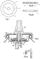
- Fig. 1 shows a top view of a valve plate Aerosol can with a mounting collar 1, one flanged mouth of an otherwise not shown Aerosol can encloses, and a delivery nozzle 2.
- the safety valve On the from the fastening collar 1 and the delivery nozzle 2 enclosed annular surface 3 is located the safety valve in the form of an annular one Notch representing breaking point 4.
- the notch 4 can from the inside, as shown in Fig. 1, or from the outside be made.
- FIG. 2a shows a cross section through part of the surface 3 of the valve plate in the closed state, while Fig. 2b that is triggered as a result of overpressure and is therefore open Represents safety valve.
- the embodiment is concentric about the valve axis running notch 5 is provided as a predetermined breaking point.
- the notch is over a circumferential range of approximately 60 ° interrupted at 6, so that when the part located within the notch 5 detaches completely from the valve plate, but only tilts (Fig. 6).
- the remaining parts of the in FIGS. 3 to 6 illustrated embodiment are known per se for example from DE 29 16 699 C2. An explanation of this Parts will only be made in the following, as far as Understanding of the invention is required.
- the only The indicated aerosol can 7 has one at the edges at 8 flanged mouth, which with a valve plate 9th is closed, a seal 10 being provided.
- the valve plate 9 is shaped such that between one inward circumferential fold 11 and one disc-shaped part 12 the edges of a valve seal 13 and a membrane 14 are clamped.
- the membrane 14 is integrally connected to a closure body 15, the Through channels for two in the aerosol can and in one not shown elastic container within the Contains liquids contained in the aerosol can.
- the valve is opened by pressure on a foam head 16, a Extension 17 of the foam head in a blind bore 18 Closure body 15 penetrates and this far down that moves the passageways from the seal are released and the liquids via grooves 19 am lower end of the extension 17 flow into the foam head 16 can.
- the predetermined breaking point 5 tears overpressure so that the inner part of the Valve plates with the valve tipping up. Doing so by means of suitable tolerances, that the one in FIG. 6 Foam head, not shown, hinders this tilting.
Landscapes
- Chemical & Material Sciences (AREA)
- Dispersion Chemistry (AREA)
- Engineering & Computer Science (AREA)
- Mechanical Engineering (AREA)
- Containers And Packaging Bodies Having A Special Means To Remove Contents (AREA)
- Filling Or Discharging Of Gas Storage Vessels (AREA)
- Nozzles (AREA)
Abstract
Description
- Fig. 1
- eine vereinfachte Draufsicht auf ein erstes Ausführungsbeispiel,
- Fig. 2
- Schnittdarstellungen des Sicherheitsventils bei dem ersten Ausführungsbeispiel vor und nach einer Auslösung,
- Fig. 3
- eine Schnittdarstellung eines zweiten Ausführungsbeispiels,
- Fig. 4
- ein Detail aus Fig. 3,
- Fig. 5
- eine Draufsicht eines Teils des Ausführungsbeispiels nach Fig. 4 bei abgenommenem Schaumkopf und
- Fig. 6
- eine Schnittdarstellung des Ausführungsbeispiels nach Fig. 4 nach einer Auslösung.
Claims (8)
- Behälter für druckgasbeaufschlagte Flüssigkeiten, wobei eine Mündung des Behälters mit einem ein Ventil tragenden Ventilteller abgedeckt ist und der Ventilteller mindestens eine die Dicke des Ventiltellers reduzierende Einkerbung als Sicherheitsventil aufweist, dadurch gekennzeichnet, daß die Einkerbung (4; 5) ringförmig verläuft und eine Fläche einschließt, deren Größe bei einem vorgegebenen Überdruck im Inneren des Behälters eine zum Aufreißen an der Einkerbung (4; 5) ausreichende Kraft zur Folge hat.
- Behälter nach Anspruch 1, dadurch gekennzeichnet, daß die Fläche die Achse des Ventils einschließt.
- Behälter nach einem der Ansprüche 1 oder 2, dadurch gekennzeichnet, daß die Einkerbung (5) an einer Stelle (6) des Umfangs unterbrochen ist.
- Behälter nach Anspruch 3, dadurch gekennzeichnet, daß die Unterbrechung (6) einen Umfangswinkel zwischen 10° und 90° einnimmt.
- Behälter nach einem der Ansprüche 2 bis 4, bei dem der Ventilteller in einem inneren Bereich zur Aufnahme einer Dichtungsringscheibe ausgebildet ist, die zwischen einem in Richtung auf die Ventilachse gefalteten Rand und einem von dem Rand beabstandeten scheibenförmigen Teil des Ventiltellers gehalten wird, dadurch gekennzeichnet, daß die Einkerbung (5) im scheibenförmigen Teil (12) angeordnet ist.
- Behälter nach Anspruch 5, dadurch gekennzeichnet, daß die Einkerbung (5) in einem Randbereich des scheibenförmigen Teils (12) angeordnet ist.
- Behälter nach einem der Ansprüche 5 oder 6, dadurch gekennzeichnet, daß der Durchmesser der ringförmigen Einkerbung (5) im wesentlichen dem Durchmesser der Dichtungsringscheibe (13) entspricht.
- Behälter nach einem der Ansprüche 5 bis 7, dadurch gekennzeichnet, daß der scheibenförmige Teil (12) einen umlaufenden Absatz aufweist und daß die Einkerbung (5) außerhalb des umlaufenden Absatzes angeordnet ist.
Applications Claiming Priority (2)
| Application Number | Priority Date | Filing Date | Title |
|---|---|---|---|
| DE19632777 | 1996-08-14 | ||
| DE19632777A DE19632777A1 (de) | 1996-08-14 | 1996-08-14 | Behälter für druckgasbeaufschlagte Flüssigkeiten |
Publications (4)
| Publication Number | Publication Date |
|---|---|
| EP0825131A1 true EP0825131A1 (de) | 1998-02-25 |
| EP0825131A2 EP0825131A2 (de) | 1998-02-25 |
| EP0825131A3 EP0825131A3 (de) | 1998-05-20 |
| EP0825131B1 EP0825131B1 (de) | 2003-09-10 |
Family
ID=7802626
Family Applications (1)
| Application Number | Title | Priority Date | Filing Date |
|---|---|---|---|
| EP97108737A Expired - Lifetime EP0825131B1 (de) | 1996-08-14 | 1997-05-31 | Behälter für druckgasbeaufschlagte Flüssigkeiten |
Country Status (6)
| Country | Link |
|---|---|
| US (1) | US5848740A (de) |
| EP (1) | EP0825131B1 (de) |
| JP (1) | JPH1081378A (de) |
| BR (1) | BR9704353A (de) |
| DE (2) | DE19632777A1 (de) |
| ES (1) | ES2206629T3 (de) |
Cited By (2)
| Publication number | Priority date | Publication date | Assignee | Title |
|---|---|---|---|---|
| EP0896926A1 (de) | 1997-08-11 | 1999-02-17 | Monarch Marking Systems, INC. | Handetikettiergerät |
| DE19906576A1 (de) * | 1999-02-17 | 2000-08-24 | Wella Ag | Aerosolbehälter |
Families Citing this family (5)
| Publication number | Priority date | Publication date | Assignee | Title |
|---|---|---|---|---|
| DE19710541A1 (de) * | 1997-03-14 | 1998-09-17 | Ehrensperger C Ag | Als Ventileinsatz für unter Druck stehende Fluidbehälter dienende Vorrichtung |
| US7077171B2 (en) * | 2004-05-21 | 2006-07-18 | Interdynamics, Inc. | Controlled leakage container and method |
| DE102008053716B4 (de) * | 2008-10-29 | 2012-09-27 | Khs Gmbh | Behälter, insbesondere großvolumiger Einwegbehälter aus Kunststoff wie beispielweise Keg zur Aufnahme von Getränken |
| KR101186931B1 (ko) | 2010-06-09 | 2012-09-28 | 주식회사 승일 | 과압가스 배출이 가능한 분사용기 및 그의 밸브 어셈블리 |
| US10113780B2 (en) | 2011-11-14 | 2018-10-30 | The Armor All/Stp Products Company | Refrigerant charging assemblies and methods of use |
Citations (5)
| Publication number | Priority date | Publication date | Assignee | Title |
|---|---|---|---|---|
| US2757964A (en) * | 1953-07-16 | 1956-08-07 | Bridgeport Brass Co | High pressure fluid dispensing device |
| US3292826A (en) * | 1965-01-18 | 1966-12-20 | Abplanalp Robert Henry | Aerosol can protected against explosion |
| US3918610A (en) * | 1974-10-23 | 1975-11-11 | Aluminum Co Of America | Safety vent for a pressure container |
| EP0262070A1 (de) * | 1986-09-19 | 1988-03-30 | Emerson Electric Co. | Veränderter Sicherheitsdeckel mit Einkerbung für verschlossenen Behälter und Verfahren zu seiner Herstellung |
| DE9204922U1 (de) * | 1992-04-09 | 1992-06-11 | Ewald Euscher GmbH & Co, 4800 Bielefeld | Mit einem Treibgas gefüllte Sprühdose |
Family Cites Families (6)
| Publication number | Priority date | Publication date | Assignee | Title |
|---|---|---|---|---|
| US3074602A (en) * | 1958-11-26 | 1963-01-22 | Shillady Marion Charlton | Pressure relief devices for pressure vessels and methods of making the same |
| JPS52135409A (en) * | 1976-05-07 | 1977-11-12 | Motoo Fukuda | Explosionnproof means for accumulated containers having valve members |
| US4610370A (en) * | 1985-12-30 | 1986-09-09 | Amoco Corporation | Pressure release vent |
| US5042675A (en) * | 1990-05-04 | 1991-08-27 | Ballard Battery Systems Corporation | Container pressure release vent |
| FR2669094B1 (fr) * | 1990-11-09 | 1993-02-12 | Oreal | Valve de distribution pour un recipient contenant un fluide sous pression gazeuse et recipient equipe d'une telle valve. |
| US5197622A (en) * | 1992-08-17 | 1993-03-30 | Gte Products Corporation | Vent pressure relief device |
-
1996
- 1996-08-14 DE DE19632777A patent/DE19632777A1/de not_active Withdrawn
-
1997
- 1997-05-31 DE DE59710715T patent/DE59710715D1/de not_active Expired - Fee Related
- 1997-05-31 EP EP97108737A patent/EP0825131B1/de not_active Expired - Lifetime
- 1997-05-31 ES ES97108737T patent/ES2206629T3/es not_active Expired - Lifetime
- 1997-08-01 US US08/904,372 patent/US5848740A/en not_active Expired - Fee Related
- 1997-08-06 JP JP9225674A patent/JPH1081378A/ja active Pending
- 1997-08-13 BR BR9704353A patent/BR9704353A/pt not_active Application Discontinuation
Patent Citations (5)
| Publication number | Priority date | Publication date | Assignee | Title |
|---|---|---|---|---|
| US2757964A (en) * | 1953-07-16 | 1956-08-07 | Bridgeport Brass Co | High pressure fluid dispensing device |
| US3292826A (en) * | 1965-01-18 | 1966-12-20 | Abplanalp Robert Henry | Aerosol can protected against explosion |
| US3918610A (en) * | 1974-10-23 | 1975-11-11 | Aluminum Co Of America | Safety vent for a pressure container |
| EP0262070A1 (de) * | 1986-09-19 | 1988-03-30 | Emerson Electric Co. | Veränderter Sicherheitsdeckel mit Einkerbung für verschlossenen Behälter und Verfahren zu seiner Herstellung |
| DE9204922U1 (de) * | 1992-04-09 | 1992-06-11 | Ewald Euscher GmbH & Co, 4800 Bielefeld | Mit einem Treibgas gefüllte Sprühdose |
Cited By (3)
| Publication number | Priority date | Publication date | Assignee | Title |
|---|---|---|---|---|
| EP0896926A1 (de) | 1997-08-11 | 1999-02-17 | Monarch Marking Systems, INC. | Handetikettiergerät |
| DE19906576A1 (de) * | 1999-02-17 | 2000-08-24 | Wella Ag | Aerosolbehälter |
| DE19906576B4 (de) * | 1999-02-17 | 2007-08-02 | Wella Ag | Aerosolbehälter |
Also Published As
| Publication number | Publication date |
|---|---|
| DE59710715D1 (de) | 2003-10-16 |
| BR9704353A (pt) | 1998-12-22 |
| JPH1081378A (ja) | 1998-03-31 |
| EP0825131B1 (de) | 2003-09-10 |
| EP0825131A3 (de) | 1998-05-20 |
| ES2206629T3 (es) | 2004-05-16 |
| US5848740A (en) | 1998-12-15 |
| DE19632777A1 (de) | 1998-02-19 |
Similar Documents
| Publication | Publication Date | Title |
|---|---|---|
| DE69013914T2 (de) | Ausgiesser für flakons oder dergleichen mit einem element zum durchstechen einer verschlussmembran. | |
| DE2951147C2 (de) | Überdruck-Sicherheitsvorrichtung | |
| EP0106280B1 (de) | Ventileinsatz für eine Zweikammer-Druckgaspackung | |
| DE3422546C2 (de) | Behälter-Verschlußkappe | |
| DE2811092C2 (de) | Flasche zur Aufnahme und Abgabe von sterilen Flüssigkeiten | |
| DE102007035728B4 (de) | Vorrichtung zum Öffnen und Verschließen eines Getränkebehälters | |
| DE69108174T2 (de) | Ausgabeventil für einen Behälter mit einer unter einem Druck eines Gases stehenden Flüssigkeit und mit einem derartigen Ventil versehener Behälter. | |
| DE3532395A1 (de) | Berstfaehige fluiddruck-entlastungsvorrichtung | |
| DE2844944A1 (de) | Ausgiesseinsatz mit wiederfuellsperre | |
| DE1501747C3 (de) | Druckbehälter mit Abgabeventil und einer Sicherheitseinrichtung zur Druckentlastung | |
| EP0098810B1 (de) | Verschlusskappe, insbesondere Garantie-Verschlusskappe für Flaschen | |
| DE2312487A1 (de) | Verschlusskappe fuer einen behaelter mit wulstrandmuendung | |
| EP0152761A2 (de) | Vorrichtung zum Herstellen und Versprühen einer aus wenigstens zwei Komponenten, z.B. Flüssigkeiten, und einem Treibgas bestehenden Mischung | |
| DE2027320A1 (de) | Kappenverschluß | |
| EP0322366A2 (de) | Schnappverschluss mit Originalitätssicherung | |
| EP0825131B1 (de) | Behälter für druckgasbeaufschlagte Flüssigkeiten | |
| EP0269068B1 (de) | Aerosol-Verpackung | |
| DE3019650C2 (de) | Tankdeckel für Brennstofftanks in Fahrzeugen | |
| EP0825131A2 (de) | Behälter für druckgasbeaufschlagte Flüssigkeiten | |
| DE819607C (de) | Ventil fuer unter Druck stehende Mittel | |
| EP0382146B1 (de) | Behälterverschluss mit Innendruckbegrenzer | |
| DE1815188C3 (de) | Verschluß für Aerosol-Behälter | |
| DE2361350B1 (de) | Verschluß für pharmazeutische Flaschen | |
| DE2236068A1 (de) | Ventil fuer druckgaspackungen | |
| EP0318657A1 (de) | Behälter mit integrierter Überdrucksicherung |
Legal Events
| Date | Code | Title | Description |
|---|---|---|---|
| PUAI | Public reference made under article 153(3) epc to a published international application that has entered the european phase |
Free format text: ORIGINAL CODE: 0009012 |
|
| 17P | Request for examination filed |
Effective date: 19970531 |
|
| AK | Designated contracting states |
Kind code of ref document: A1 Designated state(s): DE ES FR GB IT |
|
| PUAF | Information related to the publication of a search report (a3 document) modified or deleted |
Free format text: ORIGINAL CODE: 0009199SEPU |
|
| PUAL | Search report despatched |
Free format text: ORIGINAL CODE: 0009013 |
|
| D17D | Deferred search report published (deleted) | ||
| K1C1 | Correction of patent application (title page) published |
Effective date: 19980225 |
|
| AK | Designated contracting states |
Kind code of ref document: A3 Designated state(s): DE ES FR GB IT |
|
| AKX | Designation fees paid |
Free format text: DE ES FR GB IT |
|
| RBV | Designated contracting states (corrected) |
Designated state(s): DE ES FR GB IT |
|
| 17Q | First examination report despatched |
Effective date: 20021009 |
|
| GRAH | Despatch of communication of intention to grant a patent |
Free format text: ORIGINAL CODE: EPIDOS IGRA |
|
| GRAH | Despatch of communication of intention to grant a patent |
Free format text: ORIGINAL CODE: EPIDOS IGRA |
|
| GRAA | (expected) grant |
Free format text: ORIGINAL CODE: 0009210 |
|
| AK | Designated contracting states |
Kind code of ref document: B1 Designated state(s): DE ES FR GB IT |
|
| REG | Reference to a national code |
Ref country code: GB Ref legal event code: FG4D Free format text: NOT ENGLISH |
|
| REF | Corresponds to: |
Ref document number: 59710715 Country of ref document: DE Date of ref document: 20031016 Kind code of ref document: P |
|
| GBT | Gb: translation of ep patent filed (gb section 77(6)(a)/1977) | ||
| REG | Reference to a national code |
Ref country code: ES Ref legal event code: FG2A Ref document number: 2206629 Country of ref document: ES Kind code of ref document: T3 |
|
| ET | Fr: translation filed | ||
| PG25 | Lapsed in a contracting state [announced via postgrant information from national office to epo] |
Ref country code: GB Free format text: LAPSE BECAUSE OF NON-PAYMENT OF DUE FEES Effective date: 20040531 |
|
| PG25 | Lapsed in a contracting state [announced via postgrant information from national office to epo] |
Ref country code: ES Free format text: LAPSE BECAUSE OF NON-PAYMENT OF DUE FEES Effective date: 20040601 |
|
| PLBE | No opposition filed within time limit |
Free format text: ORIGINAL CODE: 0009261 |
|
| STAA | Information on the status of an ep patent application or granted ep patent |
Free format text: STATUS: NO OPPOSITION FILED WITHIN TIME LIMIT |
|
| 26N | No opposition filed |
Effective date: 20040614 |
|
| GBPC | Gb: european patent ceased through non-payment of renewal fee | ||
| PG25 | Lapsed in a contracting state [announced via postgrant information from national office to epo] |
Ref country code: IT Free format text: LAPSE BECAUSE OF NON-PAYMENT OF DUE FEES;WARNING: LAPSES OF ITALIAN PATENTS WITH EFFECTIVE DATE BEFORE 2007 MAY HAVE OCCURRED AT ANY TIME BEFORE 2007. THE CORRECT EFFECTIVE DATE MAY BE DIFFERENT FROM THE ONE RECORDED. Effective date: 20050531 |
|
| REG | Reference to a national code |
Ref country code: ES Ref legal event code: FD2A Effective date: 20040601 |
|
| PGFP | Annual fee paid to national office [announced via postgrant information from national office to epo] |
Ref country code: DE Payment date: 20080530 Year of fee payment: 12 |
|
| REG | Reference to a national code |
Ref country code: FR Ref legal event code: ST Effective date: 20100129 |
|
| PG25 | Lapsed in a contracting state [announced via postgrant information from national office to epo] |
Ref country code: FR Free format text: LAPSE BECAUSE OF NON-PAYMENT OF DUE FEES Effective date: 20090602 |
|
| PGFP | Annual fee paid to national office [announced via postgrant information from national office to epo] |
Ref country code: FR Payment date: 20080424 Year of fee payment: 12 |
|
| PG25 | Lapsed in a contracting state [announced via postgrant information from national office to epo] |
Ref country code: DE Free format text: LAPSE BECAUSE OF NON-PAYMENT OF DUE FEES Effective date: 20091201 |