EP0825143A2 - Machine à bobiner un fil continu - Google Patents
Machine à bobiner un fil continu Download PDFInfo
- Publication number
- EP0825143A2 EP0825143A2 EP97114120A EP97114120A EP0825143A2 EP 0825143 A2 EP0825143 A2 EP 0825143A2 EP 97114120 A EP97114120 A EP 97114120A EP 97114120 A EP97114120 A EP 97114120A EP 0825143 A2 EP0825143 A2 EP 0825143A2
- Authority
- EP
- European Patent Office
- Prior art keywords
- winding
- turret
- spindle
- carrier
- machine according
- Prior art date
- Legal status (The legal status is an assumption and is not a legal conclusion. Google has not performed a legal analysis and makes no representation as to the accuracy of the status listed.)
- Ceased
Links
- 238000004804 winding Methods 0.000 title claims abstract description 212
- 230000033001 locomotion Effects 0.000 claims abstract description 49
- 238000000034 method Methods 0.000 claims description 4
- 230000007704 transition Effects 0.000 claims 1
- 238000011161 development Methods 0.000 description 4
- 230000018109 developmental process Effects 0.000 description 4
- 230000000694 effects Effects 0.000 description 3
- 238000012856 packing Methods 0.000 description 3
- 238000010276 construction Methods 0.000 description 2
- 230000002093 peripheral effect Effects 0.000 description 2
- 230000000712 assembly Effects 0.000 description 1
- 238000000429 assembly Methods 0.000 description 1
- 230000015572 biosynthetic process Effects 0.000 description 1
- 230000001419 dependent effect Effects 0.000 description 1
Images


Classifications
-
- B—PERFORMING OPERATIONS; TRANSPORTING
- B65—CONVEYING; PACKING; STORING; HANDLING THIN OR FILAMENTARY MATERIAL
- B65H—HANDLING THIN OR FILAMENTARY MATERIAL, e.g. SHEETS, WEBS, CABLES
- B65H67/00—Replacing or removing cores, receptacles, or completed packages at paying-out, winding, or depositing stations
- B65H67/04—Arrangements for removing completed take-up packages and or replacing by cores, formers, or empty receptacles at winding or depositing stations; Transferring material between adjacent full and empty take-up elements
- B65H67/044—Continuous winding apparatus for winding on two or more winding heads in succession
- B65H67/048—Continuous winding apparatus for winding on two or more winding heads in succession having winding heads arranged on rotary capstan head
-
- B—PERFORMING OPERATIONS; TRANSPORTING
- B65—CONVEYING; PACKING; STORING; HANDLING THIN OR FILAMENTARY MATERIAL
- B65H—HANDLING THIN OR FILAMENTARY MATERIAL, e.g. SHEETS, WEBS, CABLES
- B65H54/00—Winding, coiling, or depositing filamentary material
- B65H54/02—Winding and traversing material on to reels, bobbins, tubes, or like package cores or formers
- B65H54/40—Arrangements for rotating packages
- B65H54/52—Drive contact pressure control, e.g. pressing arrangements
-
- B—PERFORMING OPERATIONS; TRANSPORTING
- B65—CONVEYING; PACKING; STORING; HANDLING THIN OR FILAMENTARY MATERIAL
- B65H—HANDLING THIN OR FILAMENTARY MATERIAL, e.g. SHEETS, WEBS, CABLES
- B65H2701/00—Handled material; Storage means
- B65H2701/30—Handled filamentary material
- B65H2701/31—Textiles threads or artificial strands of filaments
Definitions
- the invention relates to a winding machine for winding a running Thread to a bobbin according to the preamble of claim 1.
- the winding spindle by means of the rotating movement of a revolver during winding moved away from the stationary pressure roller.
- the winding spindle is on a swing arm mounted relative to the turret by means of a force transducer is pivotable.
- the winding spindle In the winding area, the winding spindle is closed with the forming coil pressed against the fixed pressure roller.
- the rotary motion the turret to form the coil is controlled so that the relative position of the rocker on the turret remains unchanged.
- the investment power between the pressure roller and the spool is from the power transmitter given.
- the winding area is the size of the turret diameter dependent.
- the spool In the winding machine known from DE 25 23 771, the spool is used receiving winding spindle by means of a linear guide during winding moved straight away from a pressure roller. The direction of action remains the contact force of the pressure roller relative to the coil surface constant. The pressing force is determined by means of a pneumatic cylinder.
- the evasive movement between the pressure roller and the Coil staggered in stages with different directions of movement.
- Each of the directions of movement is characterized by a typical guideway, on which the winding spindle is moved.
- the particular advantage here lies in the fact that the changes in the weight component are very targeted the pressure roller due to the change in relative position between the coil and Pressure roller is used to influence the system force. In addition can make thick bobbins while maintaining small dimensions of the bobbin turret be wrapped.
- the contact force between the spool and the pressure roller is at one movable pressure roller essentially by the weight of Pressure roller determined.
- the invention is now based on the knowledge that the contact force that results from the weight of the pressure roller or at fixed pressure roller is determined by the direction of action the position of the pressure roller to the spool can be changed.
- the Tracking force in a very simple way due to the evasive movement of the coil or the pressure roller during winding. Especially When building a coil, it is advantageous if the contact force can be changed.
- Another advantage of the invention lies in the possibility of combination and in the variation of the number and sequence of the stages for changing the Center distance. This allows very individual reel assemblies to be used wild winding as well as with a precision winding.
- the development of the winding machine according to claim 2 is special advantageous to essentially in the first phase of winding with a constant investment power. This will be the first thread layers not damaged if the investment power is too high or if the investment power is too low wrapped too loosely.
- the Spool spindle relative to the pressure roller preferably with a carrier on the stationary Revolver moves.
- the winding spindle on a move straight or slightly curved guideway so that the position changed only slightly between the pressure roller and the spool becomes.
- the further course of winding e.g. to increase the Packing density is an advantage of an increase in asset strength, which is indicated by a Evasion movement of the coil is effected by means of the turret rotation. The movement on the turret reveals a constant change in Position created between the pressure roller and the spool. With that the Weight component of the investment power influenced.
- the design of the winding machine according to claim 3 is particularly for a winding is suitable, in which the spool initially increases with increasing Investment power and in the further course of the winding cycle with as constant as possible Investment force is wrapped.
- the development of the invention according to claim 8 is particularly of Advantage to threads with a low titer or threads with a low Winding thread speeds.
- the winding machine When winding threads with relatively large titers, such as for carpet yarn, the winding machine according to claim 9 is preferred executed. It is particularly advantageous if the drive of the Carrier and / or the turret by means of frequency-controlled electric motors he follows.
- the configuration of the winding machine according to the invention as claimed in claim 10 is particularly useful when catching the thread on an empty tube at the beginning of the Reel travel is an advantage. This creates opportunities to use the winding spindle the empty sleeve from the outer position or from the inner position in the Swing in the thread run. This allows the thread to run in unison, i.e. Empty tube and thread have the same direction of movement, or in the opposite direction, i.e. the thread and the empty tube have opposite directions of movement, to be caught.
- the development of the winding machine according to claim 11 has the Advantage that in the stage in which the carrier the evasive movement of the Performs winding spindle, the contact force between the bobbin and the pressure roller remains essentially constant.
- the design of the winding machine according to claim 12 shows an advantageous Drive device for the carrier of the winding spindle.
- Size of the evasive movement of the winding spindle, which is driven by the Schweinge is designed, regardless of the dimensions of the winding turret.
- This version is therefore particularly suitable for compact design To wind coils with a relatively large diameter.
- the winding machine according to the invention is characterized through a particularly flexible drive combination of the carrier and the Turret off.
- the drive of the spindle turret and the drive of the Turret turrets are advantageously controlled so that an overlay the rotary movement is possible. This allows the geometric relationships when winding between the pressure roller and the winding spindle and thus also changing the investment power in different ways.
- the drives can be formed by converter-controlled individual motors. Both Drives can be advantageously controlled by a programmable controller couple. This allows any combination of the rotary movements of the Spindle turret and the winding turret of the winding machine abandoned will. A predetermined profile of the contact pressure can thus be applied in the winding area passed between the pressure roller and the spool.
- the embodiment is the winding machine according to claim 14 is particularly suitable.
- the winding machine according to the invention is particularly for the variants suitable where the pressure roller is fixed in relation to the spool.
- control the drive motors of the turret and the carrier by means of a sensor that measures the contact force between the coil surface and the pressure roller is detected.
- the control of the winding turret which has become known from EP 03 74 536 but can also be used without difficulty on the drive of the carrier expand.
- the movement of the pressure roller on a Swing arm is mounted, recorded and used to control the drives.
- the mobility of the pressure roller can also be advantageous Increased parking time can be used. For this, at the beginning of the Winding travel of both the winding turret and the carrier in the winding area not powered. Thus, the pressure roller from the growing diameter of the coil pushed out of its position. After this the stroke limit of the pressure roller is reached, the carrier or the Winding turret activated so that the pressure roller is in its original position resumes.
- Fig. 1 is a schematic side view of a winding machine according to the invention shown.
- a thread 1 runs over a head thread guide 2 to a traversing device.
- the traversing device consists of a traversing drive 6 and the wings 3.
- the wings 3 alternately guide the thread 1 along a ruler 4 back and forth within the limits of a traversing stroke.
- Of the Thread 1 then runs on a pressure roller 5.
- the pressure roller 5 is partially wrapped around the thread 1 and then onto a spool 17 filed.
- the coil 17 is formed on a bobbin tube 16, which on a rotatable winding spindle 14 is inserted.
- the pressure roller 5 movable radially to the coil with a contact force on Scope of the coil 17.
- the winding spindle 14 is in turn cantilevered a rocker 13 mounted.
- the rocker 13 is with one Swivel bearing 15 attached to a rotatable turret 11.
- the revolver 11 is rotatably arranged in a machine frame with a bearing 20.
- the rocker 13 is relative to the turret by means of a linear drive 28 pivotable from an outer position to an inner position or vice versa.
- the linear drive 28 is also with the attachment 29 on the turret 11 attached.
- the rocker 13 pivoted with the mounted winding spindle 14 such that the winding spindle located outside of the turret 11.
- the Spindle turret 11 a recess 22 is arranged.
- the winding spindle 14 is driven.
- the drive could be both by a driven pressure roller 5 as well as by a direct one Spindle drive.
- the pressure roller 5 is provided with a sensor 19 equipped with a control device 10 through the sensor line 31 connected is.
- the linear drive 28 can be controlled by means of the control device 10 via control line 33 or the winding turret drive (41) via the control line 32 can be controlled.
- the winding-up process is divided into several stages, the evasive movement of the bobbin being carried out with different means in each stage.
- the pressure roller 5 is brought into circumferential contact with the bobbin 17, a predetermined contact force, for example supported by a force generator on the pressure roller, acting on the bobbin surface.
- a predetermined contact force for example supported by a force generator on the pressure roller, acting on the bobbin surface.
- the winding begins in the first stage.
- the position of the pressure roller essentially does not change.
- the evasive movement for forming the coil 17 is carried out by means of the rocker 13, the winding spindle 14 being guided on a part-circular guideway to an inner relative position on the winding turret 11.
- the winding turret drive is not activated in this phase of winding.
- the deflection movement of the rocker is predetermined by means of the control device 10 by the linear drive 28.
- the Swing arm can be moved continuously or step by step. So that the peripheral contact between the pressure roller 5 and the spool 17 is not interrupted during winding, a predetermined minimum contact force or a change in position on the pressure roller is measured by means of the sensor 19 and signaled to the control device 10.
- the control device 10 is programmed in such a way that, depending on the winding situation, either the linear drive 28 or the winding turret drive (41) is activated.
- the winding machine from FIG. 1 is different Levels of winding shown.
- the coil 17 is like this widely grown that the rocker 13 on the inner relative position Has reached turret turret 11. That would be the first stage of winding completed.
- the relative position between the pressure roller 5 and the spool 17 has changed only slightly. So in this phase the Component of the system force, which results from the weight of the pressure roller resulted, remained essentially constant.
- 3 is the other Sequence of the winding process shown.
- the evasive movement of the coil 17th is carried out in the second stage by rotating the turret. In this phase of the winding process is due to the change in position between the pressure roller 5 and the coil 17 a constant change in Investment power causes.
- control device 10 can also be programmed such that several times a change between the first stage and the second stage is carried out.
- the contact force acting between the pressure roller and the spool results from the weight of the pressure roller.
- 4 shows the force ratio between the pressure roller 5 and the spool 17.
- the weight of the pressure roller is designated G, which has a vertical direction of action.
- the contact force P A which acts between the pressure roller 5 and the spool 17, has the connecting line between the axis center point M A of the pressure roller and the axis center point M S of the winding spindle as the direction of action.
- the axis center M S of the winding spindle will move on a circular guideway F T , the center of which is formed by the axis center M T of the pivot axis of the carrier or the rocker.
- the coil 17 will move in the direction of movement R T.
- the axis center M S of the winding spindle would move on a circular guideway F R , which has the axis center M R of the winding turret as the center.
- the coil 17 would move in the direction of movement R R.
- the deviation between the direction of action of the contact force P A and the direction of movement R of the coil is characterized by an angle ⁇ .
- an angle ⁇ 1 is spanned between the effective direction of the contact force P A and the direction of movement R T caused by the carrier.
- the angle ⁇ 2 is spanned between the effective direction of the contact force PA and the direction of movement R R generated by the coil turret.
- the angle ⁇ 2 is much larger than the angle ⁇ 1. This will result in a relatively strong increase in contact force P A when the turret rotates during the winding cycle.
- the winding machine according to the invention thus offers the possibility of setting a contact force which is desirable for the formation of the bobbin simply by changing the direction of movement of the winding spindle.
- the weight G of the pressure roller could be increased or relieved by a force sensor as required by a constant value.
- the winding spindle is in a bearing block 37 stored.
- the bearing block 37 is in a linear guide 38 guided on the winding turret.
- the linear drive 28 By means of the linear drive 28, the Winding spindle from an outer position to an inner position and vice versa be moved.
- This version has the particular advantage that the carrier movement does not change the position between the pressure roller 5 and the coil 17 is given.
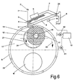
- Fig. 6 the view of a winding machine is shown schematically, at which the spindle 14 is mounted on a spindle turret 12.
- the winding machine has a revolving turret 11, which by means of the bearing 20 in a machine frame 9 is rotatably mounted.
- the winding turret 11 is there driven by an electric motor (41).
- the spindle turret 12 is rotatably mounted eccentrically with the bearing 21.
- the spindle turret 12 is driven by an electric motor (41).
- the winding spindle 14 is supported cantilevered.
- the winding spindle 14 is located in the winding area.
- Position runs the thread 1 over the head thread guide 2 to the traversing device.
- the traversing device is as wing traversing with the wings 3 trained.
- the wings 3 alternately guide the thread 1 along the guideline 4 back and forth within the limits of the traversing stroke.
- the string runs on the pressure roller 5.
- the pressure roller 5 is from The thread is partially looped and placed directly on the bobbin 17.
- the Coil 17 is formed on the winding tube 16 and rotates with the winding spindle 14.
- the pressure roller 5 is mounted on a rocker 8.
- the Swing arm 8 is connected in the swivel joint 25 to the machine frame 9. Below the rocker 8, a sensor 19 is arranged, which with its control device 10 is connected.
- the control device 10 is each with the drive motors of the spindle turret and the drive motor of the turret connected.
- the control device 10 is programmed in such a way that it first drives the Spindle turret 12 activated.
- the spindle turret 12 turns 24 move the winding spindle 14 relative to the fixed winding turret, so that the center distance between the pressure roller 5 and the winding spindle 14 enlarged. In this situation the drive of the winding turret is not activated.
- the second stage Winding of the turret 11 rotated when the turret 12 is stationary.
- Fig. 7 is a schematic sectional view of the winding machine Fig. 6 shown.
- the winding spindle 14 is located in the winding area.
- the winding spindle 14 is in the spindle turret by means of the bearing 30 12 stored.
- the winding spindle 14 is driven by means of the spindle drive 27. So that the peripheral speed on the coil surface during the coil travel can be kept constant, the speed of the pressure roller 5 detected by the sensor 35 and the control device 10 fed.
- the control device 10 converts the signals into control pulses, which are fed to the spindle drive 27 and thus the drive of the Spool spindle 14 controls.
- the motor 42 of the spindle turret 12 is preferred arranged in the turret.
- the spindle turret is preferred driven by a chain drive.
- the motor 41 of the turret 11 is arranged on the machine frame 9.
Landscapes
- Replacing, Conveying, And Pick-Finding For Filamentary Materials (AREA)
- Winding Filamentary Materials (AREA)
Applications Claiming Priority (2)
| Application Number | Priority Date | Filing Date | Title |
|---|---|---|---|
| DE19633790 | 1996-08-22 | ||
| DE19633790 | 1996-08-22 |
Publications (2)
| Publication Number | Publication Date |
|---|---|
| EP0825143A2 true EP0825143A2 (fr) | 1998-02-25 |
| EP0825143A3 EP0825143A3 (fr) | 1998-05-13 |
Family
ID=7803293
Family Applications (1)
| Application Number | Title | Priority Date | Filing Date |
|---|---|---|---|
| EP97114120A Ceased EP0825143A3 (fr) | 1996-08-22 | 1997-08-14 | Machine à bobiner un fil continu |
Country Status (5)
| Country | Link |
|---|---|
| US (1) | US6027061A (fr) |
| EP (1) | EP0825143A3 (fr) |
| KR (1) | KR100282034B1 (fr) |
| CN (1) | CN1082018C (fr) |
| TW (1) | TW363044B (fr) |
Cited By (2)
| Publication number | Priority date | Publication date | Assignee | Title |
|---|---|---|---|---|
| DE102005044487A1 (de) * | 2005-09-16 | 2007-03-22 | Maschinenfabrik Rieter Ag | Aufwindevorrichtung für Endlosfäden |
| FR2918977A1 (fr) * | 2007-07-16 | 2009-01-23 | Ritm Soc Par Actions Simplifie | Dispositif pour systemes de renvidage ou de bobinage |
Families Citing this family (2)
| Publication number | Priority date | Publication date | Assignee | Title |
|---|---|---|---|---|
| KR100656933B1 (ko) * | 2005-05-27 | 2006-12-13 | 위니아만도 주식회사 | 전자기기 케이스 |
| KR102230806B1 (ko) | 2019-03-14 | 2021-03-19 | 양선 | 필라멘트 이탈방지가이드 및 이를 이용한 3d프린터 |
Citations (4)
| Publication number | Priority date | Publication date | Assignee | Title |
|---|---|---|---|---|
| DE2523771A1 (de) | 1974-05-28 | 1975-12-11 | Ici Ltd | Garnaufspulvorrichtung |
| US4298171A (en) | 1977-09-23 | 1981-11-03 | Rieter Machine Works, Ltd. | Winding apparatus for endless filaments having an automatic bobbin tube changer |
| EP0374536A2 (fr) | 1988-12-22 | 1990-06-27 | B a r m a g AG | Machine de bobinage |
| DE4321111A1 (de) | 1992-06-29 | 1994-01-05 | Barmag Barmer Maschf | Aufspulmaschine |
Family Cites Families (8)
| Publication number | Priority date | Publication date | Assignee | Title |
|---|---|---|---|---|
| US3409238A (en) * | 1967-03-28 | 1968-11-05 | Du Pont | Continuous yarn windup apparatus |
| US3532278A (en) * | 1968-10-31 | 1970-10-06 | Du Pont | Yarn winding apparatus |
| US4114820A (en) * | 1974-05-28 | 1978-09-19 | Imperial Chemical Industries Limited | Yarn winding apparatus |
| JPH05162925A (ja) * | 1991-12-13 | 1993-06-29 | Teijin Seiki Co Ltd | 糸条の切替巻取機 |
| JP3211541B2 (ja) * | 1994-02-24 | 2001-09-25 | 村田機械株式会社 | 紡糸巻取機及びそのボビン位置制御方法 |
| JP3284806B2 (ja) * | 1995-01-18 | 2002-05-20 | 村田機械株式会社 | 巻取機のボビン位置制御方法 |
| JPH08290870A (ja) * | 1995-04-24 | 1996-11-05 | Murata Mach Ltd | 巻取機のボビン位置調整方法及びその装置 |
| EP0799787B1 (fr) * | 1996-04-04 | 2002-07-31 | B a r m a g AG | Bobinoir |
-
1997
- 1997-08-14 EP EP97114120A patent/EP0825143A3/fr not_active Ceased
- 1997-08-21 CN CN97116200A patent/CN1082018C/zh not_active Expired - Fee Related
- 1997-08-21 TW TW086111998A patent/TW363044B/zh active
- 1997-08-22 KR KR1019970040130A patent/KR100282034B1/ko not_active Expired - Fee Related
- 1997-08-22 US US08/917,071 patent/US6027061A/en not_active Expired - Fee Related
Patent Citations (4)
| Publication number | Priority date | Publication date | Assignee | Title |
|---|---|---|---|---|
| DE2523771A1 (de) | 1974-05-28 | 1975-12-11 | Ici Ltd | Garnaufspulvorrichtung |
| US4298171A (en) | 1977-09-23 | 1981-11-03 | Rieter Machine Works, Ltd. | Winding apparatus for endless filaments having an automatic bobbin tube changer |
| EP0374536A2 (fr) | 1988-12-22 | 1990-06-27 | B a r m a g AG | Machine de bobinage |
| DE4321111A1 (de) | 1992-06-29 | 1994-01-05 | Barmag Barmer Maschf | Aufspulmaschine |
Cited By (2)
| Publication number | Priority date | Publication date | Assignee | Title |
|---|---|---|---|---|
| DE102005044487A1 (de) * | 2005-09-16 | 2007-03-22 | Maschinenfabrik Rieter Ag | Aufwindevorrichtung für Endlosfäden |
| FR2918977A1 (fr) * | 2007-07-16 | 2009-01-23 | Ritm Soc Par Actions Simplifie | Dispositif pour systemes de renvidage ou de bobinage |
Also Published As
| Publication number | Publication date |
|---|---|
| CN1174808A (zh) | 1998-03-04 |
| CN1082018C (zh) | 2002-04-03 |
| EP0825143A3 (fr) | 1998-05-13 |
| KR100282034B1 (ko) | 2001-10-24 |
| KR19980018902A (ko) | 1998-06-05 |
| TW363044B (en) | 1999-07-01 |
| US6027061A (en) | 2000-02-22 |
Similar Documents
| Publication | Publication Date | Title |
|---|---|---|
| EP0374536B1 (fr) | Machine de bobinage | |
| DE2509413C3 (de) | Vorrichtung zum Aufwickeln von drahtförmigem oder bandförmigem Material in mehreren Wickellagen auf eine angetriebene Trommel | |
| DE3242092C2 (fr) | ||
| DE102006018428B4 (de) | Verfahren und Vorrichtung zum Verlegen von langgestrecktem Wickelgut | |
| EP0914287A1 (fr) | Procede d'embobinage d'un fil arrivant en continu | |
| EP0114642A1 (fr) | Machine à bobiner | |
| DE112007001233B4 (de) | Verfahren und Vorrichtung zur Garnchangierung bei der Aufwicklung des Garns auf eine Spule | |
| DE2349577A1 (de) | Wickelvorrichtung fuer fadenmaterial | |
| DE3713112A1 (de) | Schraubenfederwickelanlage | |
| DE2458853A1 (de) | Wickeleinrichtung fuer konische, durch friktion angetriebene kreuzspulen | |
| CH693380A5 (de) | Verfahren und Vorrichtung zum Aufspulen eines kontinuierlich zulaufenden Fadens. | |
| EP0056858A1 (fr) | Procédé pour bobiner des matériaux filiformes, en particulier des câbles | |
| EP0799787B1 (fr) | Bobinoir | |
| EP0825143A2 (fr) | Machine à bobiner un fil continu | |
| EP4122858A1 (fr) | Procédé permettant de faire fonctionner un poste de travail d'une machine à bobiner, ainsi que machine à bobiner | |
| EP1151950A2 (fr) | Procédé de fonctionnement d'une machine textile pour la fabrication de bobines à spires croisées | |
| DE3010018A1 (de) | Verfahren und vorrichtung zum maschinellen herstellen von rohrfoermigen wickelkoerpern | |
| DE2623175A1 (de) | Garnwickelvorrichtung | |
| DE2159646A1 (de) | Vorrichtung zum Verdrillen von Drahten | |
| DE102005003334A1 (de) | Aufspulvorrichtung | |
| DE2364284B1 (de) | Spulmaschine | |
| EP2669228B1 (fr) | Bobine de fil enroulée ainsi que dispositif et procédé de fabrication de la bobine de fil | |
| DE2916458A1 (de) | Vorrichtung zum aufspulen textiler faeden | |
| DE4321111A1 (de) | Aufspulmaschine | |
| EP0752385B1 (fr) | Méthode et dispositif de va-et-vient pour des matériaux filiforms ou des rubans |
Legal Events
| Date | Code | Title | Description |
|---|---|---|---|
| PUAI | Public reference made under article 153(3) epc to a published international application that has entered the european phase |
Free format text: ORIGINAL CODE: 0009012 |
|
| AK | Designated contracting states |
Kind code of ref document: A2 Designated state(s): CH DE FR GB IT LI |
|
| AX | Request for extension of the european patent |
Free format text: AL;LT;LV;RO;SI |
|
| PUAL | Search report despatched |
Free format text: ORIGINAL CODE: 0009013 |
|
| AK | Designated contracting states |
Kind code of ref document: A3 Designated state(s): AT BE CH DE DK ES FI FR GB GR IE IT LI LU MC NL PT SE |
|
| AX | Request for extension of the european patent |
Free format text: AL;LT;LV;RO;SI |
|
| 17P | Request for examination filed |
Effective date: 19981111 |
|
| AKX | Designation fees paid |
Free format text: CH DE FR GB IT LI |
|
| RBV | Designated contracting states (corrected) |
Designated state(s): CH DE FR GB IT LI |
|
| 17Q | First examination report despatched |
Effective date: 20010803 |
|
| GRAG | Despatch of communication of intention to grant |
Free format text: ORIGINAL CODE: EPIDOS AGRA |
|
| STAA | Information on the status of an ep patent application or granted ep patent |
Free format text: STATUS: THE APPLICATION HAS BEEN REFUSED |
|
| 18R | Application refused |
Effective date: 20021107 |