EP0825798A2 - Hörereinrichtung und Terminalgerät - Google Patents
Hörereinrichtung und Terminalgerät Download PDFInfo
- Publication number
- EP0825798A2 EP0825798A2 EP19970660083 EP97660083A EP0825798A2 EP 0825798 A2 EP0825798 A2 EP 0825798A2 EP 19970660083 EP19970660083 EP 19970660083 EP 97660083 A EP97660083 A EP 97660083A EP 0825798 A2 EP0825798 A2 EP 0825798A2
- Authority
- EP
- European Patent Office
- Prior art keywords
- speech
- signal
- earphone unit
- ear
- microphone
- Prior art date
- Legal status (The legal status is an assumption and is not a legal conclusion. Google has not performed a legal analysis and makes no representation as to the accuracy of the status listed.)
- Withdrawn
Links
Images




Classifications
-
- B—PERFORMING OPERATIONS; TRANSPORTING
- B60—VEHICLES IN GENERAL
- B60R—VEHICLES, VEHICLE FITTINGS, OR VEHICLE PARTS, NOT OTHERWISE PROVIDED FOR
- B60R7/00—Stowing or holding appliances inside vehicle primarily intended for personal property smaller than suit-cases, e.g. travelling articles, or maps
- B60R7/04—Stowing or holding appliances inside vehicle primarily intended for personal property smaller than suit-cases, e.g. travelling articles, or maps in driver or passenger space, e.g. using racks
- B60R7/06—Stowing or holding appliances inside vehicle primarily intended for personal property smaller than suit-cases, e.g. travelling articles, or maps in driver or passenger space, e.g. using racks mounted on or below dashboards
Definitions
- the present invention relates to an earphone unit mounted in the auditory tube (also called auditory canal) or on the ear, which unit comprises voice reproduction means for converting an electric signal into acoustic sound signal and for forwarding the sound signal into the user's ear, and speech detection means for detecting the speech of the user of the earphone unit from the user's said same auditory tube.
- the earphone unit is suitable for use in connection with a terminal device, especially in connection with a mobile station.
- the invention is related to a terminal device incorporating or having a separate earphone unit and to a method of reproduction and detection of sound.
- earpiece for either both ears or only for one ear, from which earpiece in general a separate microphone bar extending to mouth or the side of mouth is protruding.
- the earpiece is either of a type to be mounted on the ear or in the auditory tube.
- the microphone used is air connected, either a pressure or a pressure gradient microphone.
- the required amplifiers and other electronics are typically placed in a separate device. If a wireless system is concerned, it is possible to place some of the required electronics in connection with the earpiece device, and the rest in a separate transceiver unit. It is also possible to integrate the transceiver unit in the earpiece device.
- Patent publication US 5,343,523 describes an earphone solution designed for pilots and telephone operators, in which earpieces are mounted on the ears and a separate microphone suspended from a bar is mounted in front of the mouth.
- a separate error microphone has been arranged in connection with the earpieces, by utilizing which microphone some of the environmental noise detected by the user can be cancelled and the intelligibility of speech can be improved in this way.
- Patent publication US 5,426,719 presents a device which also acts as a combined hearing protector and as a means of communication.
- the microphone is placed in one earpiece and the ear capsule respectively in the other earpiece. This means that a device according to any of the two patent publications requires using both ears, which makes the device bulky and limits the field of use of the device.
- Patent publication WO 94/06255 presents an ear microphone unit for placement in one ear only.
- the unit is mounted in a holder for placement in the outer ear.
- the holder further has a sound generator. Between the sound generator and the microphone is mounted a vibration absorbing unit. Also the sound generator is embedded in a thin layer of attenuation foam.
- an improved earphone unit which unit facilitates placing of a microphone and an ear capsule in same auditory tube or on the same ear and which has means for eliminating sounds produced into the auditory tube by the ear capsule from sounds detected by the microphone.
- This improves the detection of the user's speech, which is registered via the auditory tube, especially when the user speaks simultaneously as sound is reproduced by the ear capsule.
- telephones such as mobile phones this is needed especially in double talk situations, i.e. when both the near end and far end speaker speak simultaneously.
- microphones and ear capsules any means of conversion prior known to a person skilled in the art that convert acoustic energy into electric form (microphone), and electric energy into acoustic form (ear capsule, loudspeaker).
- the invention presents a new solution for determining the acoustic coupling of a microphone and a loudspeaker and for optimizing voice quality using digital signal processing.
- the earphone unit according to the invention is suitable for use in occasions in which environmental noise prevents from using a conventional microphone placed in front of mouth.
- the small size of the earphone unit according to the invention enables using the device in occasions in which small size is an advantage e.g. due to inconspicuousnes.
- the earphone unit according to the invention is particularly suitable for use e.g. in connection with a mobile station or a radio telephone while moving in public places.
- the use of the earphone unit is not limited to wireless mobile stations, but it is equally possible to use the earphone unit in connection with even other terminal devices.
- One preferable field of use is to connect the earphone unit to a traditional telephone or other wire-connected telecommunication terminal device. It is equally possible to use the earphone unit according to the invention in connection with various interactive computer programs, radio tape recorders and dictating machines. It is also possible to integrate the earphone unit as a part of a terminal device as presented in the embodiments below.
- the acoustic leakage of the ear capsule may be beyond control, which can disturb the operation of the device.
- An acoustic leakage means e.g. a situation in which environmental noise leaks past an ear capsule placed in the auditory tube into the auditory tube. If an earphone unit according to the invention consisting of a microphone and an ear capsule is placed in a separate device outside the auditory tube, it is particularly important to have the acoustic leakage under control.
- the transfer functions between the various components of the system must be known. Because the transfer function between the microphone capsule and the ear capsule is not constant, the transfer function must be monitored. Monitoring of the transfer function can be carried out e.g. through measurements based on noise. In order to improve voice quality and the intelligibility of speech, it is possible to divide the detection and reproduction of speech in various frequency bands which are processed digitally.
- the ear-connectable earphone unit and the terminal device arrangement according to the invention comprises means for eliminating sounds produced into the auditory tube by said sound reproduction means from sounds detected by said speech detection means.
- said sound reproduction means and said speech detection means have been arranged in the terminal device close to each other in a manner for connecting both simultaneously to one and the same ear of a user, and the terminal device further comprising means for eliminating sounds produced into the auditory tube by said sound reproduction means from sounds detected by said speech detection means.
- Figure 1 presents earphone unit 11 according to the invention, which makes it possible to place microphone capsule 13 and ear capsule 12 in same auditory tube 10.
- Error microphone 14 is located on the outer surface of earphone unit 11.
- Earphone unit 11 has been given such a form that intrusion of external noise 17' into auditory tube 10 has been prevented as efficiently as possible.
- External noise 17' consists of e.g. noise produced by working machinery and speech of persons nearby.
- the source of noise is in figure 1 represented by block 17 and the sound advancing from source of noise 17 directly to error microphone 14 is presented with reference 17".
- the advantage of earphone unit 11 is its small size and its suitability for noisy environment.
- Microphone capsule 13 and ear capsule 12 can be physically located in relation to each other in a number of ways.
- Figures 2A and 2B present alternative placing of microphone capsule 13, error microphone 14 and ear capsule 12, and figure 2C presents utilizing of dynamic ear capsule 150 as both microphone capsule 13 and ear capsule 12.
- microphone capsule 13 has as an example been placed in front of ear capsule 12 close to acoustic axis 142. It is possible to integrate microphone capsule 13 in the body of ear capsule 12, or it can be mounted using supports 141.
- Arrow 12' presents sound emitted by ear capsule 12.
- Figure 2B presents a solution in which ear capsule 12 has been installed in the other, auditory tube 10 side, end of earphone unit 11.
- Ear capsule 12 is integrated in the body of earphone unit 11 e.g. using supports 144. Slots or apertures 145 have been arranged between the housing of earphone unit 11 and supports 144 to the otherwise closed microphone chamber in which microphone capsule 13 has been placed.
- Microphone capsule 13 is integrated in the body of earphone unit 11 or fixed solidly on e.g. supports 146.
- Space 148 has been arranged behind microphone chamber 147 for electric components required by earphone unit 11, such as processor 34, amplifiers and A/D and D/A-converters (figure 4).
- Error microphone 14 which has an acoustic connection to noise 17" arriving from the source of noise 17 has been placed in space 149 in the end of earphone unit 11 opposite to ear capsule 12.
- Figure 2C presents an embodiment of earphone unit 11, in which separate ear capsule 12 and microphone capsule 13 have been replaced with dynamic ear capsule 150 which is capable of acting simultaneously as a sound reproducing and receiving component.
- dynamic ear capsules 150 e.g. a piezoelectric converters, which have been described in more detail in publication Anderson, E.H. and Hagood, N.W. 1994 Simultaneous piezoelectric sensing / actuation: analysis and applications to controlled structures, Journal of Sound and Vibration, vol 174, 617-639.
- the solution of integrating ear capsule 12 and microphone capsule 13 preferably reduces the need for space of earphone unit 11. Such a construction is also simpler in its mechanical realization. It is also possible to use in the earphone unit 11 according to the invention other ways of placing and realizing microphones 13 and 14 and ear capsule 12, different in their realization.
- the human speech is generated in the larynx 20 (figure 1) in the upper end of the windpipe, in which the vocal cords 15 are situated. From the vocal cords 15 the speech is transferred through the Eustachian tube connecting the throat and the middle ear to the eardrum 16. Also connected to the eardrum 16 are the auditory ossicles (not shown in the figure ) in the middle ear, over which the sound is forwarded into the inner ear (not shown in the figure) where the sensing of sound takes place. The vibrations of the eardrum 16 relays the speech through the auditory tube 10 to the microphone capsule 13 in the auditory tube 10 end of earphone unit 11. When speech is transferred to the user of earphone unit 11 over ear capsule 12, this speech is sensed by the eardrum 16.
- block 24 illustrates sound signals received by microphone capsule 13. They consist of three components: speech signal 15' originated in the vocal cords, ear capsule signal 12' reproduced by ear capsule 12 in the auditory tube 10 and noise signal 17" caused by external sources of noise 17.
- speech signal 15' originated in the vocal cords
- ear capsule signal 12' reproduced by ear capsule 12 in the auditory tube 10
- noise signal 17" caused by external sources of noise 17.
- signals 12' and 17' which are disturbing from the point of view of speech signal 15', are strived to be eliminated e.g. in two different stages.
- ear capsule signal 12' generated by ear capsule 12 in the auditory tube 10 is removed in block 24.
- the original electric initiator of ear capsule signal 12' is known, it can be subtracted from the signal received by microphone capsule 13 using subtractor 25 provided that the transfer function between ear capsule 12 and microphone capsule 13 is known. Because the transfer function between error microphone 14 and microphone capsule 13 is essentially constant, noise signal 17' can be subtracted in second stage 25 using subtractor 27 using a method which is explained later.
- the transfer function between ear capsule 12 and microphone capsule 13 is determined e.g. using so-called MLS (Maximum Length Sequence) -signal.
- MLS Maximum Length Sequence
- a known MLS -signal is fed into the auditory tube 10 with ear capsule 12, the response caused by which signal is measured with microphone capsule 13.
- This measuring is executed preferably at such discrete moments when no other information is transferred to the user over ear capsule 12.
- any sound signal as the known measuring sound signal, but it is nice from the user's point of view to use e.g. the MLS-signal resembling convenience noise.
- the noise is generated using a generator 50 (figure 5) which generates binary, seemingly random sequences (pseudo-random sequence generator), which generator is realized digitally in processor 34 (figure 4) in earphone unit 11.
- Figure 5 presents the realization of generator 50 using a n-stage shift register.
- Output 53 of the generator is, with suitably selected feed-backs 51 and 52, binary sequences repeated identically at certain intervals.
- the sequences are fed to D/A-converter 33 (figure 4), and from there further to amplifier 32 and ear capsule 12.
- the repeating frequency of the sequences depends on the number of stages n of the generator and on the choice of feed-back 51 and 52.
- n- stage generator 50 has the length of 2 n -1 bits.
- a 64-stage generator can produce a sequence which is repeated identical only after 600,000 years when 1 MHz clock frequency is used. It is prior known to a person skilled in the art that such long sequences are generally used to simulate real random noise.
- Figure 6 presents determining the transfer function.
- Ear capsule 12 is used to feed a known signal f(t) into the auditory tube 10 and the signal is detected using microphone capsule 13.
- Processor 34 saves the supplied signal f(t) in memory 37.
- signal f(t) is transformed due to the effect of impulse response h(t) (ref. 56) into form h(t)*f(t).
- signal h(t)*f(t) is directed to A/D-converter 31 and saved in memory 37.
- Signal h(t)*f(t) is a convolution of the supplied signal f(t) and the system impulse response h(t) (ref. 56). Convolution has been described e.g.
- the system impulse response h(t) is determined by calculating the cross-correlation, prior known to persons skilled in the art, of the supplied signal f(t) and the received signal h(t)*f(t).
- Impulse response h(t) in time space can be converted into the form in frequency space e.g. using FFT (Fast Fourier Transform) -transform 58, resulting in system transfer function H( ⁇ ).
- FFT Fast Fourier Transform
- H( ⁇ ) system transfer function
- Relatively low signal to noise ratio (SNR) will be sufficient for a successful measuring.
- the accuracy of the impulse response can, in addition to increasing the SNR, be improved through averaging. In preferable conditions the user will not detect the determining of the impulse response at all.
- a filter is required for compensating external signal z(t), which filter realizes impulse response k(t).
- the filter can be constructed using discrete components, but preferably it is realized digitally in processor 34. Even traditional adaptive echo canceling algorithms can be used for estimating signals y(t) and z(t).
- the acoustic coupling between microphone capsule 13 and error microphone 14 can be determined also during the operation of the device. This can be carried out by comparing the microphone signals m(t) and z'(t). When signal y'(t) is 0 and such a moment is found when the user of the device is not speaking, also x(t) is 0. In this case the remaining m(t) is essentially convolution k(t)*z'(t).
- the transfer function can be converted into the impulse response k(t) of time space using inverse Fourier- transform. This operation can be used e.g. for determining the acoustic leak of earphone unit 11 or as a help to speech synthesis e.g. when editing a user's speech.
- microphone 14 can be used even in stead of main microphone 13. It is possible to realize the choice between microphones 13 and 14 e.g. by comparing the amplitude levels of the microphone signals. In addition to this the microphone signals can be analyzed e.g. using a speech detector (VAD, Voice-Activity Detection) and further through correlation calculation, with which one can confirm that signal z'(t) arriving in error microphone 14 has sufficient resemblance with the processed signal x(t). These actions can be used for preventing noise of nearby machinery or other corresponding source of noise and speech of nearby persons from passing on after the processor. When error microphone 14 is used instead of microphone capsule 13 it is possible to obtain better voice quality in conditions with little noise.
- VAD Voice-Activity Detection
- FIG. 4 presents in more detail the internal construction of earphone unit 11.
- the signals from microphone capsule 13 and error microphone 14 are amplified in amplifiers 30 and 36 after which they are directed through A/D-converters 31 and 35 to processor 34.
- processor 34 When speech signal or MLS-signal from generator 50 is transferred to the user's auditory tube 10 they are transferred through D/A-converter 33 and amplifier 32 to ear capsule 12.
- Program codes executed by processor 34 are stored in memory 37, which is used by processor 34 also for storing e.g. the interim data required for determining impulse response h(t).
- Controller 38 which typically is a microprocessor, the required A/D- and D/A-converters 39 and processor 34 with memory 37 convert both the incoming and outgoing speech into the form required by transfer path 40.
- Transfer of speech into both directions can be carried out in either analogue or digital form to either external terminal device 121 (figure 13) or device 100, 110 (figures 11A, 11B and 12) built in connection with earphone unit 11.
- the required A/D- and D/A-conversions are executed with converter 39.
- the power supply to earphone unit 11 can be carried out over transfer path 40. If earphone unit 11 has been designed for wireless operation, the required means of transmitting and receiving 111,113 (figure 12A) and the power supply (e.g. a battery, not shown in the figure) are placed e.g. in the ear-mounted part.
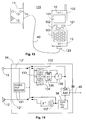
- Figure 14 presents an embodiment in which microphone signal 13" and ear capsule signal 12" transferred to different directions are separated from each other using band-pass filters 132, 133, 134 and 137.
- the band-pass filters divide the speech band into sub-bands (references 61-68, figures 7 - 10), in which case ear capsule 12 can be run on part of the sub-bands and the signal from microphone capsule 13 is correspondingly forwarded only on sub-bands which remain free.
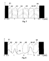
- Figure 7 presents an example of sub-bands, in which speech signal is transferred to both directions on three different frequency bands. In telephone systems the speech band is typically 300 to 3400 Hz.
- frequency bands 300 to 700 Hz, 1.3 to 1.9 kHz and 2.4 to 3.0 kHz, or sub-bands 62, 64 and 66 are utilized directly.
- the signal repeated by ear capsule 12 contains correspondingly frequency bands 700 Hz to 1.3 kHz, 1.9 to 2.4 kHz and 3.0 to 3.4 kHz, or sub-bands 63, 65 and 67.
- frequency bands below 300 Hz (reference 61) and higher than 3.4 kHz (reference 68) are not used.
- the number of sub-bands has not been limited for reasons of principle, but to the more sub-bands the frequency range in use is divided, the better voice quality is obtained. As a counterweight to this the required processing capacity increases.
- band limiting is started using band-pass filters 132, 133, 134 and 137, the last of which comprises three separate filters for the signal from ear capsule 12.
- band limiting is stopped, in which situation signal 13" from microphone capsule 13 is connected directly to controller 38 and ear capsule signal 12" directly from controller 38 to ear capsule 12.
- Digital signal processing enables improving speech quality during band limiting.
- the contents of the missing sub-bands can be predicted based upon adjacent sub-bands. This is realized e.g. in frequency level by generating the energy spectrum of a missing sub-band based upon the energy spectrum of the limiting frequency of the previous and the next known sub-band.
- Generating of the missing sub-bands can be carried out e.g. using curve adaptation of first or higher degree prior known to persons skilled in the art. Even with simple prediction methods, such as curve adaptation of first degree, in most situations a better voice quality is obtained compared to only band limited signal, although due to the far advanced human auditory sense speech signal is intelligible even without predicting the missing sub-bands.
- the predicting has been described in more detail in connection with the explanation of figures 8 to 10.
- the predicting is realized using predictor 136 (figure 14) in the transmitting end.
- Band-pass filters 132, 133 and 134 and summing unit 135 are used in connection with the predicting.
- Figure 8 presents signal 70 in frequency level as measured by microphone capsule 13 in auditory tube 10.
- the measuring band is wider than speech band 300 to 3400 Hz and accordingly signal 70 contains also frequency components under 300 Hz and over 3.4 kHz.
- Figure 9 presents microphone signal 70 in frequency space, limited to sub-bands 62, 64 and 66, which signal in its new form consists of three separate components 81, 82 and 83 of the frequency space.
- band limited microphone signal 70 in frequency space looks like in figure 9 also in the receiving end, containing components 81, 82 and 83.
- the speech signal is badly distorted because e.g. frequency peak 70' (figure 10) contained in band 63 is missing totally.
- components 81, 82 and 83 form an understandable whole, because a human being is capable of understanding even a very distorted and imperfect speech signal.
- a curve adaptation of first degree has been adapted between signal components 81, 82 and 83 of figure 9, in which in all simplicity a straight line has been placed over the missing sub-bands.
- straight line 91 is adjusted between the higher limit frequency (700 Hz) of sub-band 81 and the lower limit frequency (1.3 kHz) of sub-band 82, which gives the contents of sub-band 63.
- predicting prediction 92 is obtained for sub-band 65 and prediction 93 for area 67.
- sub-band 61 or lower than 300 Hz can be used, although it contains sounds of the human body, such as heartbeats and sounds of breathing and swallowing.
- the predicted, previously missing signal components 91, 92 and 93 are generated utilizing processor 34 and controller 38 before transferring to A/D- and D/A-converter 39 and transfer path 40.
- FIGS 11A and 11B present another embodiment of earphone unit 11 according to the invention.
- earphone unit 11 has been integrated in connection with mobile station 100.
- both ear capsule 12 and microphone capsule 13 have been placed in the same end of mobile station 100.
- Protective element 106 made of soft and elastic material, e.g. rubber, has been arranged in connection with ear capsule 12 and microphone capsule 13. The important function of the element is to prevent external noise 17' form entering the auditory tube 10 when mobile station 100 is lifted on ear 18 in operating position.
- Error microphone 14 used for eliminating external noise 17' has been placed in the side edge of mobile station 100.
- ear capsule 12 and microphone capsule 13 are placed next to each other, the distance between the human ear and mouth does not limit the dimensioning of mobile station 100, in which case mobile station 100 can be realized in even very small size.
- Limitations for the mechanical realization of mobile station 100 are set mainly by display 101, menu keys 102 and numeric keys 103, unless they are replaced with e.g. a speech-controlled user interface.
- FIG. 12 presents another application example of earphone unit 11 according to the invention.
- simplified mobile station 111 with antenna 113 has been arranged in connection with earphone unit 11.
- Simplified mobile station 111 comprises a typical mobile station, e.g. a GSM mobile telephone, the typical radio parts prior known to persons skilled in the art and other parts of signal processing, such as the parts for handling the baseband signal for establishing a wireless radio connection to a base station (not shown in the figure).
- a base station e.g. a GSM mobile telephone
- Controller 118 can resemble a traditional mobile station or e.g. an infrared controller prior known from television apparatuses.
- Transceiver 115 has been arranged to transfer, e.g. in the infrared range, information between controller 118 and transceiver 114 arranged in connection with earphone unit 11 in order to control the operation of mobile station 111.
- Wireless mobile station 110 consisting of earphone unit 11 according to the invention, simplified mobile station 111 and transceiver 114, can using controller 118 operate preferably as a wireless mobile station mounted in one ear.
- the signal processing required for reducing the size of earphone unit 11, such as predicting missing frequency bands, can also be realized in processing means 117 arranged in controller 118.
- Figure 13 presents mobile station system 120, which consists of earphone unit 11 according to the invention and traditional mobile station 121.
- Earphone unit 11 is connected to mobile station 121 using e.g. connection cable 40.
- Connection cable 40 is used for transferring speech signals in electric form from earphone unit 11 to mobile station 121 and vice versa in either analogue or digital form.
- earphone unit 11 for enabling the so called "hands-free" function.
- a separate microphone has been needed, placed e.g. in connection with connection cable 40, but by using earphone unit 11 according to the invention a separate microphone is preferably not needed.
- processing means 34, 37, 38 essential for the operation of earphone unit 11 can be placed either in earphone unit 11 itself, or preferably the functions are carried out in processing means 122 of mobile station 121, in which case it is possible to realize earphone unit 11 in very small size and at low manufacturing cost. If desired, processing means 34, 37, 38, 39 can also be placed in connector 123 of connection cable 40. In this case it is possible to connect earphone unit 11 with special connection cable 40 to a standard mobile station, in which specific processing means 122 are not needed.
Landscapes
- Engineering & Computer Science (AREA)
- Mechanical Engineering (AREA)
- Headphones And Earphones (AREA)
- Vehicle Step Arrangements And Article Storage (AREA)
Applications Claiming Priority (2)
| Application Number | Priority Date | Filing Date | Title |
|---|---|---|---|
| FR9603173A FR2746068B1 (fr) | 1996-03-13 | 1996-03-13 | Boite a gants notamment de vehicules automobiles |
| FR9603173 | 1996-08-13 |
Publications (1)
| Publication Number | Publication Date |
|---|---|
| EP0825798A2 true EP0825798A2 (de) | 1998-02-25 |
Family
ID=9490154
Family Applications (1)
| Application Number | Title | Priority Date | Filing Date |
|---|---|---|---|
| EP19970660083 Withdrawn EP0825798A2 (de) | 1996-03-13 | 1997-07-14 | Hörereinrichtung und Terminalgerät |
Country Status (2)
| Country | Link |
|---|---|
| EP (1) | EP0825798A2 (de) |
| FR (1) | FR2746068B1 (de) |
Cited By (3)
| Publication number | Priority date | Publication date | Assignee | Title |
|---|---|---|---|---|
| DE19926552A1 (de) * | 1999-06-11 | 2000-12-14 | Sennheiser Electronic | Kopfhörer mit Mikrofon |
| DE10034322A1 (de) * | 2000-07-12 | 2002-01-31 | Siemens Ag | HiFi-Kopfhörer mit Mobiltelefon |
| US7529379B2 (en) | 2005-01-04 | 2009-05-05 | Motorola, Inc. | System and method for determining an in-ear acoustic response for confirming the identity of a user |
Families Citing this family (5)
| Publication number | Priority date | Publication date | Assignee | Title |
|---|---|---|---|---|
| FR2810936B1 (fr) | 2000-06-29 | 2002-10-11 | Peugeot Citroen Automobiles Sa | Boite de rangement pour l'amenagement de l'habitacle d'un vehicule automobile, notamment du type boite a gants |
| US9630564B1 (en) * | 2015-10-30 | 2017-04-25 | Nissan North America, Inc. | Vehicle storage compartment structure |
| DE102017115033A1 (de) * | 2017-07-05 | 2019-01-10 | Man Truck & Bus Ag | Fahrzeug, insbesondere Omnibus, mit einer Gepäckaufbewahrungsvorrichtung |
| DE102018222850A1 (de) * | 2018-12-21 | 2020-06-25 | Brose Fahrzeugteile SE & Co. Kommanditgesellschaft, Coburg | Kraftfahrzeugbaugruppe zur Anordnung an einem Fahrzeugboden |
| EP3722155B1 (de) * | 2019-04-08 | 2021-03-03 | Audi AG | Kraftfahrzeug mit einem staufach in einer innenverkleidung |
Family Cites Families (2)
| Publication number | Priority date | Publication date | Assignee | Title |
|---|---|---|---|---|
| JPH0648237A (ja) * | 1992-07-31 | 1994-02-22 | Kanto Auto Works Ltd | 多目的機能を備えた回転式カップホルダ |
| DE4409562C1 (de) * | 1994-03-21 | 1995-04-27 | Daimler Benz Ag | Ablagefach für Fahrzeuginnenräume |
-
1996
- 1996-03-13 FR FR9603173A patent/FR2746068B1/fr not_active Expired - Fee Related
-
1997
- 1997-07-14 EP EP19970660083 patent/EP0825798A2/de not_active Withdrawn
Cited By (4)
| Publication number | Priority date | Publication date | Assignee | Title |
|---|---|---|---|---|
| DE19926552A1 (de) * | 1999-06-11 | 2000-12-14 | Sennheiser Electronic | Kopfhörer mit Mikrofon |
| DE19926552B4 (de) * | 1999-06-11 | 2013-10-10 | Sennheiser Electronic Gmbh & Co. Kg | Kopfhörer mit Mikrofon |
| DE10034322A1 (de) * | 2000-07-12 | 2002-01-31 | Siemens Ag | HiFi-Kopfhörer mit Mobiltelefon |
| US7529379B2 (en) | 2005-01-04 | 2009-05-05 | Motorola, Inc. | System and method for determining an in-ear acoustic response for confirming the identity of a user |
Also Published As
| Publication number | Publication date |
|---|---|
| FR2746068A1 (fr) | 1997-09-19 |
| FR2746068B1 (fr) | 1998-05-29 |
Similar Documents
| Publication | Publication Date | Title |
|---|---|---|
| US6415034B1 (en) | Earphone unit and a terminal device | |
| KR102266080B1 (ko) | 주파수 의존 측음 교정 | |
| US6690800B2 (en) | Method and apparatus for communication operator privacy | |
| CN107452367B (zh) | 在耳用扬声器通道中的适应性噪音消除的协调控制 | |
| JP5395895B2 (ja) | 信号処理方法およびシステム | |
| KR102196012B1 (ko) | 트랜스듀서 상태의 검출에 기초하여 오디오 트랜스듀서의 성능을 향상시키는 방법들 및 시스템들 | |
| US9066167B2 (en) | Method and device for personalized voice operated control | |
| CN100420149C (zh) | 具有有源均衡的通信设备及其方法 | |
| JP5400166B2 (ja) | 受話器およびステレオとモノラル信号を再生する方法 | |
| US20060120537A1 (en) | Noise suppressing multi-microphone headset | |
| US20190149915A1 (en) | Method and device for in ear canal echo suppression | |
| EP3213527B1 (de) | Minderung der okklusion der eigenen stimme bei kopfhörern | |
| WO2014158475A1 (en) | Systems and methods for locating an error microphone to minimize or reduce obstruction of an acoustic transducer wave path | |
| EP2719195A1 (de) | Erzeugung eines maskierungssignals auf einer elektronischen vorrichtung | |
| CN105049976B (zh) | 一种声音降噪的方法、耳机和终端 | |
| EP3840402B1 (de) | Elektronische wearable vorrichtung mit tief-frequenz-rauschverminderung | |
| JP4415831B2 (ja) | 携帯通信端末及びその漏れ音声低減方法 | |
| JPH08340590A (ja) | イヤホンマイク装置 |
Legal Events
| Date | Code | Title | Description |
|---|---|---|---|
| PUAI | Public reference made under article 153(3) epc to a published international application that has entered the european phase |
Free format text: ORIGINAL CODE: 0009012 |
|
| AK | Designated contracting states |
Kind code of ref document: A2 Designated state(s): AT BE CH DE DK ES FI FR GB GR IE IT LI LU MC NL PT SE |
|
| RAP1 | Party data changed (applicant data changed or rights of an application transferred) |
Owner name: NOKIA CORPORATION |
|
| STAA | Information on the status of an ep patent application or granted ep patent |
Free format text: STATUS: THE APPLICATION HAS BEEN WITHDRAWN |
|
| 18W | Application withdrawn |
Withdrawal date: 20021008 |