EP0826501B2 - Dispositif utilisé pour ajuster un rouleau d'encrage ou de mouillage dans une machine à imprimer - Google Patents
Dispositif utilisé pour ajuster un rouleau d'encrage ou de mouillage dans une machine à imprimer Download PDFInfo
- Publication number
- EP0826501B2 EP0826501B2 EP96810580A EP96810580A EP0826501B2 EP 0826501 B2 EP0826501 B2 EP 0826501B2 EP 96810580 A EP96810580 A EP 96810580A EP 96810580 A EP96810580 A EP 96810580A EP 0826501 B2 EP0826501 B2 EP 0826501B2
- Authority
- EP
- European Patent Office
- Prior art keywords
- roller
- spindle
- control surface
- support part
- inking
- Prior art date
- Legal status (The legal status is an assumption and is not a legal conclusion. Google has not performed a legal analysis and makes no representation as to the accuracy of the status listed.)
- Expired - Lifetime
Links
- 238000013016 damping Methods 0.000 title 1
- 238000006073 displacement reaction Methods 0.000 claims description 5
- 238000009424 underpinning Methods 0.000 claims 2
- 238000004519 manufacturing process Methods 0.000 description 5
- 238000005096 rolling process Methods 0.000 description 4
- 230000006835 compression Effects 0.000 description 2
- 238000007906 compression Methods 0.000 description 2
- 230000001960 triggered effect Effects 0.000 description 2
- 230000005540 biological transmission Effects 0.000 description 1
- 238000012512 characterization method Methods 0.000 description 1
- 238000010586 diagram Methods 0.000 description 1
- 230000013011 mating Effects 0.000 description 1
- 238000000034 method Methods 0.000 description 1
- 239000000523 sample Substances 0.000 description 1
- 238000003860 storage Methods 0.000 description 1
Images


Classifications
-
- B—PERFORMING OPERATIONS; TRANSPORTING
- B41—PRINTING; LINING MACHINES; TYPEWRITERS; STAMPS
- B41F—PRINTING MACHINES OR PRESSES
- B41F31/00—Inking arrangements or devices
- B41F31/30—Arrangements for tripping, lifting, adjusting, or removing inking rollers; Supports, bearings, or forks therefor
- B41F31/304—Arrangements for inking roller bearings, forks or supports
- B41F31/307—Sliding bearings
-
- B—PERFORMING OPERATIONS; TRANSPORTING
- B41—PRINTING; LINING MACHINES; TYPEWRITERS; STAMPS
- B41F—PRINTING MACHINES OR PRESSES
- B41F31/00—Inking arrangements or devices
- B41F31/30—Arrangements for tripping, lifting, adjusting, or removing inking rollers; Supports, bearings, or forks therefor
- B41F31/304—Arrangements for inking roller bearings, forks or supports
- B41F31/308—Swinging bearings
-
- B—PERFORMING OPERATIONS; TRANSPORTING
- B41—PRINTING; LINING MACHINES; TYPEWRITERS; STAMPS
- B41F—PRINTING MACHINES OR PRESSES
- B41F31/00—Inking arrangements or devices
- B41F31/30—Arrangements for tripping, lifting, adjusting, or removing inking rollers; Supports, bearings, or forks therefor
- B41F31/32—Lifting or adjusting devices
Definitions
- the present invention relates to a Device for setting an inking unit or Dampening roller of a printing machine regarding according to two adjacent fixed rollers the preamble of claim 1.
- the Inking unit and dampening unit rollers are adjustable are, that is, the contact pressure to the neighboring Rollers with which the adjustable rolls come into contact, even during production is customizable.
- These adjustable inking or Dampening unit rollers have a soft elastic Surface on. This can result in a permanently set Rollers the contact pressure to the neighboring rollers, with whom she is in contact. reason for that are above all the changing conditions of Machine standstill at which the contact pressure in a known manner by making an impression for example the applicator roller on the plate cylinder is adjustable up to full production speed. The higher the speed, the more the contact pressure increases.
- An influence on the contact pressure of the above Rolling can also have the temperature that when starting production from room temperature a certain operating temperature will rise what also an increase in the contact pressure Has.
- Such devices for setting inking or Dampening rollers are known.
- DE-A-38 25 517 shows such a device.
- two Adjustment devices housed that are substantially perpendicular to each other stand and with which the bearing arrangement with respect to the machine frame adjusted in any direction of a plane within the setting range can be.
- the object of the present invention is now that To design the device so that an adjustment of the corresponding Rolling in the desired manner is possible that the device easier in Structure and correspondingly cheaper to manufacture is that the Device installed in a press even when space is limited can be, and that in addition to adjusting the corresponding roller a parking of one of the adjacent rollers is made possible, the parked roller but remains in contact with the other adjacent roller.
- the device according to the invention can be constructed in a simple and space-saving manner his.
- each bearing assembly is attached to a support member which is in a bracket is held.
- the connection between bracket and supporting part is made by a Swivel lever which is pivotally held in the holder and on which the support part is pivoted. This allows the support part in easier Way to follow the control curve when the support member relative to the bracket and moved along one of the axes to adjust the roller.
- the support part In advantageously only one pivot lever is used, the support part must be provided on the side with support means, and that only the first axis, which is rotatably and non-displaceably held in the supporting part, in the middle Area is equipped with a thread, which in a corresponding Counter thread is screwed into the swivel lever so that by twisting this axis by means of a motor and a gearbox together this axis can be moved with the support part.
- control curve By using a swivel lever, the control curve have a virtually any shape so that when they are on a part is attached, which is releasably and interchangeably attached to the support member in their shape can be adapted to the desired requirements.
- guide part with respect to the bracket on which it is attached, adjustable so that when inserted the roller in the bearing arrangements the ratio of Contact pressure on the two adjacent rollers changeable and adaptable to existing needs is.
- the setting is advantageously carried out the roller automatically via a control device of selectable parameters. This gives you always one while the press is operating optimal position of the roller.
- An actuating value transmitter is advantageously used for Determination of the current position of the roller provided, which reported back to the control device can be.
- the control device can be triggered adjustment of the motor also depending on one contact pressure measured by means of a force measuring device of the roller to the adjacent rollers.
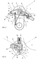
- Fig. 1 shows a schematic representation Plate cylinder 1 of a printing machine, not shown and a friction roller 2. Between the plate cylinder 1 and the friction roller 2 is an application roller 3 arranged on both sides in an inventive Device 4 is held.
- This device 4 consists essentially of a pivot lever 5, which is pivotally mounted about the axis of the friction roller 2 is.
- a guide lever 6 arranged pivotally about the axis 7.
- the guide lever 6 and thus the guide part 8 are by means of a spring 9 pressed against a control surface 10, which with respect the machine frame of the printing machine, not shown is kept stationary and in a known manner.
- the application roller 3 is in the guide lever 6 the axis 11 rotatably mounted. Via a linear drive 12, which is in operative connection with the swivel lever 5, can the device 4 around the axis of the friction roller 2 swivel.
- a linear drive 12 which is in operative connection with the swivel lever 5
- the guide part runs through this linear drive 12 8 along the control surface 10, whereby the in this guide lever 6 mounted application roller 3 in is essentially moved on a straight line 13, the runs parallel to the control surface 10.
- control surface 10 is oriented that the straight line 13 running parallel to it essentially the bisector of the angle ⁇ corresponds to that formed by two connecting lines is, each the axis 11 of the applicator roller 3 with the Axis of the plate cylinder 1 or the axis of the friction roller 2 connect.
- control surface 10 compared to the bisector of the Angle ⁇ is inclined by a certain amount, whereby when moving the applicator roller 3 to the contact pressure to the plate cylinder 1 and to the application roller 2 can no longer be changed accordingly, but in a certain ratio that is determined by the inclination of the control surface 10.
- the control surface 10 has an adjustment range 14 subsequent further area 15, which against the friction roller 2 is inclined. If now the adjustment the application roller 3 from the plate cylinder 1 and the friction roller 2 takes place, the guide part arrives 8 from the setting range 14 of the control surface 10 in the further Area 15, the guide lever 6 is through the Spring 9 pulled against the friction roller 2, the applicator roller 3 is thus turned off by the plate cylinder 1 and is only in contact with the friction roller 2.
- the Contact pressure of the application roller 3 to the friction roller 2 is determined by the force of the spring 9. In known Way can in the parked state of the application roller 3 of the plate cylinder 1, for example, the inking unit pre-inked on the press.
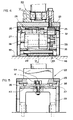
- the application roller 3, with respect to the plate cylinder 1 and the friction roller 2 to be set is in a sliding part 16 stored, the over in a receiving part 17 a linear drive 18 is slidably held.
- the receiving part 17 in turn can be moved in a guide 19 guided.
- the sliding part 16 is with a Guide part 8 equipped with a control surface 10 cooperates.
- the pressure of the spring 20 Guide part 8 pressed against the control surface 10.
- the Control surface 10 is, according to the principle Fig. 1, substantially parallel to the bisector 13 aligned.
- the control surface 10 has an adjustment range 14 and another area 15 so that the same setting options and parking the platen 3 can be done like this with the system 1 is possible.
- the journal is 21 of the application roller, not shown, in one two half existing bearing arrangement 22, whereby the replacement of an application roller in known Wise and easy to do.
- This bearing arrangement 22 is on a support member 23 by means of screws 24 attached, which has the shape of a table.
- This supporting part 23 is on its bearing arrangement 22 opposite side equipped with two tabs 25, in which a first axis 26 rotatable but fixed is stored. Pivotable about this first axis 26 one end of a pivot lever 27 is articulated.
- the other end of the pivot lever 27 is about a second axis 28 that is parallel to the first axis 27 is aligned, pivotable and fixed in a bracket 29 mounted.
- This bracket 29 is on not shown machine frame of the printing press attached.
- the first axis 26 points in its central area a thread 30, which in a corresponding Mating thread 31, arranged in swivel lever 27, is screwed in.
- On the first axis 26 is also a gear pinion 32 is rotationally fixed. With this Gear pinion 32 meshes with a gear 33 on the output shaft 34 of a gear 35 is attached.
- This Gear 35 is flanged onto an electric motor 36.
- the electric motor 36 and consequently the transmission 35 with gear 33 are attached to the pivot lever 27.
- support means 37 equipped, which in the form of rollers 38 are formed on the two edge areas of the Carrier part are attached and the essentially corresponding runways of the support member 23 and the Bracket 29 can roll.
- a component 39 is fastened on the supporting part 23 which the control surface 40 is attached accordingly the control surface 10 according to FIGS. 1 and 2.
- This control surface 40 acts with a guide part 41 together, which is attached to the bracket 29 and corresponds to the guide part 8 according to FIGS. 1 and 2.
- This control surface 40 also has an adjustment range and another area for parking the Application roller on as described for FIGS. 1 and 2 has been.
- bracket 29 and pivot lever 27 attached elastic member 42 which as Compression spring is formed, causes the support member 23rd and thus the control surface 40 against the guide part 41 are pressed.
- Fig. 4 shows the bearing assembly 22 on the support member 23 is attached.
- the first axis 26 is how already mentioned, rotatable but fixed in both Tabs 25 of the support member 23 are mounted.
- the gear pinion 32 moves accordingly also with respect to the gear 33, which is why it has a correspondingly large width.
- This load cell 26 is with a control device electrically connected as described later becomes.
- the bracket 29 is on the machine frame 53 attached to the printing press.
- Fig. 5 shows a view of the support means 37 forming rollers 38 on an edge region of the Support part 23 are provided.
- the rollers 38 are supported on the one hand essentially directly onto the supporting part 23, but act on the opposite side Plate spring 43 which is placed on the holder 29 and a slight movement of the support member 23 to the bracket 29 permits.
- Fig. 7 shows the guide part 41, which on the Bracket 29 is attached, and the control surface 40, the it is provided in component 39 which component 39 on Support member 23 is attached.
- the guide part 41 is on one adjustable eccentric 54 attached, as well 5 can be seen.
- This eccentric 54 can for example when assembling this Device can be set, for example the contact pressure of the application roller 3 to the plate cylinder 1 can be chosen larger than the contact pressure the application roller 3 to the friction roller 2.
- the component 39, in which the control surface 40 is attached be, by appropriate choice the shape of the control surface the ratio of the contact pressure for example the application roller / friction roller for pressure application roller / plate cylinder can be influenced.
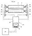
- a control device 47 is provided, such as this is shown schematically in Fig. 8.
- This can for example a programmable logic controller 48, with which the target position of the application roller 3 is specified.
- the actual position of the application roller 3 is sent to the programmable by the control value transmitter 44 Control 48 reported back.
- Control 48 By driving the motors 36, the application roller set accordingly.
- Control 48 also information are fed by the machine control 49, for example about speed, running time, arrival and departure Parking etc.
- the stored setpoints and the actual values about the location of the adjustable rollers as well as others usable influencing factors that influence the Position of the adjustable roller can have via a display 51 of the programmable logic Controller 48 are shown and controlled, they but can also be in the control device 47 attached keyboard 52 can be changed.
- this device according to the invention will optimally set the appropriate Rolling with respect to two adjacent rolls allows, the structure of this device can be kept simple, and being the setting can be controlled automatically, depending the machine parameters to be taken into account.
Landscapes
- Inking, Control Or Cleaning Of Printing Machines (AREA)
- Rotary Presses (AREA)
Claims (14)
- Dispositif de réglage d'un rouleau d'encrage ou d'un rouleau de mouillage (3) d'une machine à imprimer par rapport à deux autres rouleaux fixes voisins (1, 2) dont les extrémités de l'axe autour duquel toume ce rouleau d'encrage ou de mouillage (3) sont logées chacune dans un palier (22) qui peut être décalé, par rapport au bâti (53) de la machine à imprimer, dans un plan perpendiculaire à l'axe, et ce au moyen de moyens d'entraínement constitués dans chaque cas par un seul moteur linéaire (12, 18), ce décalage étant sensiblement parallèle à la bissectrice (13) d'un angle (α) formé par deux lignes reliant l'axe du rouleau d'encrage ou de mouillage (3) à l'axe de chacun des rouleaux voisins (1, 2), caractérisé en ce que le décalage de chacun des deux paliers (22) a lieu le long d'au moins une came (10, 40) agissant de concert avec un guidage (8, 41) et présentant au moins un domaine de réglage (14) sensiblement parallèle à la bissectrice (13), en ce que le guidage (8, 41) et la came (10, 40) sont pressés l'un contre l'autre au moyen d'un élément élastique (9, 42) et en ce que la came (10, 40) présente un autre domaine (15) contigu au domaine de réglage (14), et qui est incliné vers l'un des rouleaux (2), de telle sorte que le rouleau d'encrage ou de mouillage (3), lors du décalage l'amenant dans cet autre domaine (15), s'appuie sur l'un des rouleaux (2) sous l'effet de la force de poussée exercée par l'élément élastique (9, 42), un espace libre apparaít entre la came (10, 40) et le guidage (8, 41) et le rouleau d'encrage ou de mouillage (3) est séparé de l'autre rouleau (1).
- Dispositif selon la première revendication, caractérisé en ce que le rouleau d'encrage ou de mouillage est un toucheur (3) placé entre l'un des rouleaux (2), qui est un rouleau distributeur, et l'autre rouleau (1), qui est un cylindre porte-plaque, et en ce que la came (10, 40) est placée de telle manière que la force d'appui exercée par l'élément élastique (9, 42) soit dirigée vers le rouleau distributeur (2).
- Dispositif selon l'une des revendications 1 à 2, caractérisé en ce que chaque placement de paliers (22) est fixé sur un support (23) maintenu dans une fixation (29) montée à demeure sur le bâti (53) et par rapport à laquelle le support (23) peut se déplacer le long de la came (40), la came (40) étant montée sur le support (23) et la pièce de guidage (41) située le long de la came (40) étant montée à demeure sur la fixation (29).
- Dispositif selon la revendication 3, caractérisé en ce que le support (23) est articulé de manière à pouvoir pivoter autour d'un premier axe (26) à une extrémité d'au moins un levier pivotant (27), ce premier axe (26) étant sensiblement parallèle à la plage de réglage de la came (40), et en ce que le ou les leviers pivotants (27) soient montés dans la fixation (29), à l'autre extrémité, de manière à pouvoir pivoter autour d'un deuxième axe (28), qui est parallèle au premier axe (26).
- Dispositif selon la revendication 4, caractérisé en ce que le support (23) peut être déplacé longitudinalement le long du premier axe (26) ou du deuxième axe (28), ou des deux.
- Dispositif selon la revendication 4 ou 5, caractérisé en ce qu'il possède un levier pivotant (27) qui est fixé au support (23) de manière pivotante, sensiblement dans une partie médiane, tandis que les deux zones marginales du support (23) sont pourvues d'appuis (37) au moyen desquels, pour éviter qu'il bascule autour du premier axe (26), le support (23) s'appuie sur la fixation (29).
- Dispositif selon la revendication 6, caractérisé en ce que les appuis (37) sont réalisés sous la forme de rouleaux (38) et en ce que ceux-ci s'appuient de manière élastique, dans l'une des deux zones marginales du support (23), sur la fixation (29).
- Dispositif selon l'une des revendications 5 à 7, caractérisé en ce que le premier axe (26) est fixé au support (23) de manière à pouvoir tourner et à ne pas pouvoir être décalé, en ce que la partie médiane du premier axe (26) présente un filetage (30) vissé dans un taraudage correspondant (31) du levier pivotant (27), et en ce que le premier axe (26) peut être entraíné dans les deux sens de rotation au moyen d'un moteur (36) et d'un réducteur (35).
- Dispositif selon la revendication 8, caractérisé en ce que le moteur (36) et le réducteur (35) sont fixés au levier pivotant (27) et en ce qu'une roue dentée (33) est montée sur l'arbre de sortie du réducteur (35) et est en prise avec un pignon (32) monté sur le premier axe (26) de manière à ne pas pouvoir tourner.
- Dispositif selon l'une des revendications 3 à 9, caractérisé en ce que la came (40) est montée sur une pièce (39) qui est fixée au support (23) de façon à pouvoir être retirée et remplacée, et en ce que la pièce de guidage (41) est réglable par rapport à la fixation (29).
- Dispositif selon l'une des revendications 4 à 10, caractérisé en ce que l'élément élastique (42) est un ressort au moyen duquel le levier pivotant (27) et, par conséquent, la came (40) qui en est solidaire, peuvent être pressés contre la pièce de guidage (41).
- Dispositif selon l'une des revendications 1 à 11, caractérisé en ce qu'il est pourvu d'un système de commande (47) grâce auquel le réglage du rouleau (3) a lieu automatiquement en fonction de paramètres pouvant être sélectionnés.
- Dispositif selon l'une des revendications 1 à 12, caractérisé en ce qu'il est pourvu d'un capteur (44) de grandeur réglante servant à déterminer la position instantanée du rouleau (3).
- Dispositif selon l'une des revendications 1 à 13, caractérisé en ce qu'un système dynamométrique (45) permet de mesurer la pression d'appui du rouleau (3) sur les rouleaux voisins (1, 2).
Priority Applications (4)
| Application Number | Priority Date | Filing Date | Title |
|---|---|---|---|
| EP96810580A EP0826501B2 (fr) | 1996-09-03 | 1996-09-03 | Dispositif utilisé pour ajuster un rouleau d'encrage ou de mouillage dans une machine à imprimer |
| DE59605059T DE59605059D1 (de) | 1996-09-03 | 1996-09-03 | Vorrichtung zum Einstellen einer Farbwerks- bzw. Feuchtwerkswalze einer Druckmaschine |
| JP9235796A JP2977197B2 (ja) | 1996-09-03 | 1997-09-01 | 印刷機のインキ練り又は湿し装置ローラの調整装置 |
| US08/922,238 US5819656A (en) | 1996-09-03 | 1997-09-03 | Apparatus for adjusting an inking or dampening-device roller of a printing machine |
Applications Claiming Priority (1)
| Application Number | Priority Date | Filing Date | Title |
|---|---|---|---|
| EP96810580A EP0826501B2 (fr) | 1996-09-03 | 1996-09-03 | Dispositif utilisé pour ajuster un rouleau d'encrage ou de mouillage dans une machine à imprimer |
Publications (3)
| Publication Number | Publication Date |
|---|---|
| EP0826501A1 EP0826501A1 (fr) | 1998-03-04 |
| EP0826501B1 EP0826501B1 (fr) | 2000-04-26 |
| EP0826501B2 true EP0826501B2 (fr) | 2004-01-02 |
Family
ID=8225689
Family Applications (1)
| Application Number | Title | Priority Date | Filing Date |
|---|---|---|---|
| EP96810580A Expired - Lifetime EP0826501B2 (fr) | 1996-09-03 | 1996-09-03 | Dispositif utilisé pour ajuster un rouleau d'encrage ou de mouillage dans une machine à imprimer |
Country Status (4)
| Country | Link |
|---|---|
| US (1) | US5819656A (fr) |
| EP (1) | EP0826501B2 (fr) |
| JP (1) | JP2977197B2 (fr) |
| DE (1) | DE59605059D1 (fr) |
Families Citing this family (13)
| Publication number | Priority date | Publication date | Assignee | Title |
|---|---|---|---|---|
| DE19963944C1 (de) | 1999-12-31 | 2001-06-13 | Koenig & Bauer Ag | Verfahren zum Einstellen einer Walze einer Druckmaschine |
| ATE438510T1 (de) * | 2000-06-30 | 2009-08-15 | Komori Printing Mach | Steuerung für die farbvorrichtung von einer druckmaschine |
| JP3664242B2 (ja) * | 2001-03-02 | 2005-06-22 | 株式会社東京機械製作所 | 印刷機の液体供給装置におけるニップ幅調整装置 |
| DE10262042B4 (de) * | 2001-12-06 | 2005-11-10 | Koenig & Bauer Ag | Farbwerk mit zumindest drei Walzen bzw. Zylinder |
| JP4068063B2 (ja) | 2001-12-06 | 2008-03-26 | ケーニツヒ ウント バウエル アクチエンゲゼルシヤフト | 印刷機のローラを調節するための装置 |
| DE102004004665B4 (de) * | 2004-01-30 | 2005-12-29 | Koenig & Bauer Ag | Vorrichtung zum Einstellen einer von einer Walze in einem Walzenstreifen auf einen benachbarten Rotationskörper ausgeübten Anpresskraft und zum Anstellen der Walze an den Rotationskörper oder zum Abstellen der Walze von dem Rotationskörper |
| DE102004008090A1 (de) | 2004-02-19 | 2005-09-08 | Man Roland Druckmaschinen Ag | Vorrichtung zum Positionieren einer Walze in einem Farb- oder Feuchtwerk einer Rotationsdruckmaschine |
| DE102004031946B4 (de) * | 2004-06-30 | 2021-03-18 | Heidelberger Druckmaschinen Ag | Verfahren zum Antreiben von Walzen eines Druckwerkes einer Druckmaschine |
| ITVR20040141A1 (it) * | 2004-09-10 | 2004-12-10 | Valentini Maria Grazia | Dispositivo di supporto e ritenuta a rilascio per un mozzo di un cilindro per macchina da stampa. |
| PL1867478T3 (pl) | 2005-04-21 | 2009-07-31 | Koenig & Bauer Ag | Zespół drukujący z co najmniej dwoma współpracującymi cylindrami |
| FR2889822B1 (fr) * | 2005-08-19 | 2007-11-09 | Goss Int Montataire Sa | Unite d'impression a cylindre porte-blanchet mobile entre une position en-pression et une position hors-pression et presse d'impression correspondante. |
| DE102006011926B4 (de) * | 2006-03-15 | 2010-03-18 | Windmöller & Hölscher Kg | Verfahren zur Lageeinstellung des Druckwerks einer Druckmaschine sowie Vorrichtung zur Durchführung dieses Verfahrens |
| EP1938989A1 (fr) | 2006-12-27 | 2008-07-02 | Gimaco Ingenieur AG für Maschinenbau | Palier pour cylindre d'un mécanisme d'encrage ou de mouillage d'une presse |
Citations (1)
| Publication number | Priority date | Publication date | Assignee | Title |
|---|---|---|---|---|
| DE4400563A1 (de) † | 1994-01-11 | 1995-07-13 | Roland Man Druckmasch | Walze in einem Farbwerk oder Feuchtwerk einer Rotationsdruckmaschine |
Family Cites Families (7)
| Publication number | Priority date | Publication date | Assignee | Title |
|---|---|---|---|---|
| US2177261A (en) * | 1937-08-31 | 1939-10-24 | Goss Printing Press Co Ltd | Inking mechanism |
| DE6929358U (de) * | 1969-07-24 | 1969-11-13 | S M B Sondermaschb Gmbh | Druckwerk fuer rotationsdruckmaschinen |
| US3683805A (en) * | 1970-07-23 | 1972-08-15 | Harris Intertype Corp | Liquid handling mechanism |
| US3678849A (en) * | 1970-10-02 | 1972-07-25 | Western Printing Mach Co | Doctor blade oscillatable between plate cylinder and ink transfer roll |
| DE3825517A1 (de) * | 1988-07-27 | 1990-02-01 | Wifag Maschf | Vorrichtung zum an- und abstellen sowie einstellen von farbwerks- bzw. feuchtwerkswalzen einer druckmaschine |
| US5179898A (en) * | 1991-11-15 | 1993-01-19 | Rockwell International Corporation | Printer with roller mounting assembly |
| US5590598A (en) * | 1992-06-23 | 1997-01-07 | Keller; James J. | Horizontal sheet transfer multiple color offset rotary printing press with horizontal slide access |
-
1996
- 1996-09-03 EP EP96810580A patent/EP0826501B2/fr not_active Expired - Lifetime
- 1996-09-03 DE DE59605059T patent/DE59605059D1/de not_active Expired - Fee Related
-
1997
- 1997-09-01 JP JP9235796A patent/JP2977197B2/ja not_active Expired - Fee Related
- 1997-09-03 US US08/922,238 patent/US5819656A/en not_active Expired - Fee Related
Patent Citations (1)
| Publication number | Priority date | Publication date | Assignee | Title |
|---|---|---|---|---|
| DE4400563A1 (de) † | 1994-01-11 | 1995-07-13 | Roland Man Druckmasch | Walze in einem Farbwerk oder Feuchtwerk einer Rotationsdruckmaschine |
Also Published As
| Publication number | Publication date |
|---|---|
| EP0826501B1 (fr) | 2000-04-26 |
| DE59605059D1 (de) | 2000-05-31 |
| US5819656A (en) | 1998-10-13 |
| EP0826501A1 (fr) | 1998-03-04 |
| JPH1086340A (ja) | 1998-04-07 |
| JP2977197B2 (ja) | 1999-11-10 |
Similar Documents
| Publication | Publication Date | Title |
|---|---|---|
| EP0475890B1 (fr) | Dispositif d'essuyage pour le cylindre de plaque d'une machine d'impression en creux | |
| EP0010237B1 (fr) | Dispositif combiné de mouillage et d'encrage pour une machine à imprimer offset et procédé pour encrer et mouiller un cliché d'impression offset | |
| EP0625423B1 (fr) | Unité d'impression avec dispositif d'inclinaison et d'arrêt | |
| EP0234456B2 (fr) | Dispositif d'impression complémentaire | |
| EP0826501B2 (fr) | Dispositif utilisé pour ajuster un rouleau d'encrage ou de mouillage dans une machine à imprimer | |
| DE69217378T2 (de) | Wickelmaschine | |
| EP2195166A1 (fr) | Dispositif d'encrage d'une presse à imprimer | |
| EP0087625B1 (fr) | Dispositif pour l'application des rouleaux toucheurs sur le cylindre porte-plaque des machines d'impression et pour l'enlèvement et le réglage de ces rouleaux | |
| DE3032001A1 (de) | Maschine zur herstellung von eindeckenwellpappe mit automatischer steuerung des walzenspaltes | |
| CH648264A5 (de) | Falzvorrichtung fuer rotationsdruckmaschinen. | |
| EP1310360B1 (fr) | Machine d'impression flexographique avec des cylindres de transfert d'encre applicables de façon manuelle et automatique | |
| DE10152839A1 (de) | Verfahren zur Positionierung einer in wenigstens zwei unterschiedliche Betriebsstellungen bewegbaren Walze einer Druckmaschine und entsprechendes Farbwerk | |
| EP0653302B1 (fr) | Dispositif pour contrÔler la vitesse d'un rouleau encreur dans une machine à imprimer rotative offset | |
| CH697762B1 (de) | Vorrichtung zum Positionieren einer Walze in einem Farb- oder Feuchtwerk einer Rotationsdruckmaschine. | |
| DE69400707T2 (de) | Einrichtung zum verstellen des abstandes zwischen zylinderachsen in einer druckmaschine | |
| DE4400563C2 (de) | Walze in einem Farbwerk oder Feuchtwerk einer Rotationsdruckmaschine | |
| DE10102734A1 (de) | Vorrichtung zum Antreiben einer Reibwalze in einer Druckmaschine | |
| DE4442302A1 (de) | Vorrichtung zum axialen hin- und herbewegen von Reibwalzen im Farbwerk von Druckmaschinen | |
| DE69305404T2 (de) | Offsetdruckmaschine | |
| EP0684338B1 (fr) | Porte-lame | |
| EP0175237A2 (fr) | Dispositif d'enlèvement des rouleaux d'encrage dans les machines d'impression | |
| DE2752709A1 (de) | Farbbeschichtungsmaschine | |
| EP0384127B1 (fr) | Dispositif de réglage du registre circonférentiel dans une imprimerie rotative à feuilles | |
| DE9316916U1 (de) | Kombiniertes Feucht-Farbwerk | |
| EP1502887B1 (fr) | Procédé de préréglage d'une machine d'impression |
Legal Events
| Date | Code | Title | Description |
|---|---|---|---|
| PUAI | Public reference made under article 153(3) epc to a published international application that has entered the european phase |
Free format text: ORIGINAL CODE: 0009012 |
|
| AK | Designated contracting states |
Kind code of ref document: A1 Designated state(s): AT BE CH DE DK ES FI FR LI |
|
| AX | Request for extension of the european patent |
Free format text: AL;LT;LV;SI |
|
| 17P | Request for examination filed |
Effective date: 19980814 |
|
| AKX | Designation fees paid |
Free format text: AT BE CH DE DK ES FI FR LI |
|
| RBV | Designated contracting states (corrected) |
Designated state(s): AT BE CH DE DK ES FI FR LI |
|
| GRAG | Despatch of communication of intention to grant |
Free format text: ORIGINAL CODE: EPIDOS AGRA |
|
| 17Q | First examination report despatched |
Effective date: 19990203 |
|
| APAB | Appeal dossier modified |
Free format text: ORIGINAL CODE: EPIDOS NOAPE |
|
| APBJ | Interlocutory revision of appeal recorded |
Free format text: ORIGINAL CODE: EPIDOS IRAPE |
|
| GRAG | Despatch of communication of intention to grant |
Free format text: ORIGINAL CODE: EPIDOS AGRA |
|
| GRAH | Despatch of communication of intention to grant a patent |
Free format text: ORIGINAL CODE: EPIDOS IGRA |
|
| GRAH | Despatch of communication of intention to grant a patent |
Free format text: ORIGINAL CODE: EPIDOS IGRA |
|
| GRAA | (expected) grant |
Free format text: ORIGINAL CODE: 0009210 |
|
| AK | Designated contracting states |
Kind code of ref document: B1 Designated state(s): CH DE FI FR GB IT LI NL SE |
|
| REG | Reference to a national code |
Ref country code: CH Ref legal event code: EP |
|
| REF | Corresponds to: |
Ref document number: 59605059 Country of ref document: DE Date of ref document: 20000531 |
|
| REG | Reference to a national code |
Ref country code: CH Ref legal event code: NV Representative=s name: BOVARD AG PATENTANWAELTE |
|
| ITF | It: translation for a ep patent filed | ||
| GBT | Gb: translation of ep patent filed (gb section 77(6)(a)/1977) |
Effective date: 20000710 |
|
| ET | Fr: translation filed | ||
| PLBI | Opposition filed |
Free format text: ORIGINAL CODE: 0009260 |
|
| PLBF | Reply of patent proprietor to notice(s) of opposition |
Free format text: ORIGINAL CODE: EPIDOS OBSO |
|
| 26 | Opposition filed |
Opponent name: MAN ROLAND DRUCKMASCHINEN AG Effective date: 20010124 |
|
| NLR1 | Nl: opposition has been filed with the epo |
Opponent name: MAN ROLAND DRUCKMASCHINEN AG |
|
| PLBF | Reply of patent proprietor to notice(s) of opposition |
Free format text: ORIGINAL CODE: EPIDOS OBSO |
|
| PLBF | Reply of patent proprietor to notice(s) of opposition |
Free format text: ORIGINAL CODE: EPIDOS OBSO |
|
| REG | Reference to a national code |
Ref country code: GB Ref legal event code: IF02 |
|
| PLAW | Interlocutory decision in opposition |
Free format text: ORIGINAL CODE: EPIDOS IDOP |
|
| PLAW | Interlocutory decision in opposition |
Free format text: ORIGINAL CODE: EPIDOS IDOP |
|
| PUAH | Patent maintained in amended form |
Free format text: ORIGINAL CODE: 0009272 |
|
| STAA | Information on the status of an ep patent application or granted ep patent |
Free format text: STATUS: PATENT MAINTAINED AS AMENDED |
|
| 27A | Patent maintained in amended form |
Effective date: 20040102 |
|
| AK | Designated contracting states |
Kind code of ref document: B2 Designated state(s): CH DE FI FR GB IT LI NL SE |
|
| REG | Reference to a national code |
Ref country code: CH Ref legal event code: AEN Free format text: AUFRECHTERHALTUNG DES PATENTES IN GEAENDERTER FORM |
|
| NLR2 | Nl: decision of opposition |
Effective date: 20040102 |
|
| REG | Reference to a national code |
Ref country code: SE Ref legal event code: RPEO |
|
| NLR3 | Nl: receipt of modified translations in the netherlands language after an opposition procedure | ||
| ET3 | Fr: translation filed ** decision concerning opposition | ||
| PGFP | Annual fee paid to national office [announced via postgrant information from national office to epo] |
Ref country code: FR Payment date: 20060209 Year of fee payment: 10 |
|
| PGFP | Annual fee paid to national office [announced via postgrant information from national office to epo] |
Ref country code: FI Payment date: 20060214 Year of fee payment: 10 |
|
| PGFP | Annual fee paid to national office [announced via postgrant information from national office to epo] |
Ref country code: NL Payment date: 20060215 Year of fee payment: 10 |
|
| PGFP | Annual fee paid to national office [announced via postgrant information from national office to epo] |
Ref country code: SE Payment date: 20060217 Year of fee payment: 10 |
|
| PG25 | Lapsed in a contracting state [announced via postgrant information from national office to epo] |
Ref country code: FI Free format text: LAPSE BECAUSE OF NON-PAYMENT OF DUE FEES Effective date: 20060903 |
|
| PG25 | Lapsed in a contracting state [announced via postgrant information from national office to epo] |
Ref country code: SE Free format text: LAPSE BECAUSE OF NON-PAYMENT OF DUE FEES Effective date: 20060904 |
|
| PGFP | Annual fee paid to national office [announced via postgrant information from national office to epo] |
Ref country code: IT Payment date: 20060930 Year of fee payment: 11 |
|
| PG25 | Lapsed in a contracting state [announced via postgrant information from national office to epo] |
Ref country code: NL Free format text: LAPSE BECAUSE OF NON-PAYMENT OF DUE FEES Effective date: 20070401 |
|
| EUG | Se: european patent has lapsed | ||
| GBPC | Gb: european patent ceased through non-payment of renewal fee |
Effective date: 20060903 |
|
| NLV4 | Nl: lapsed or anulled due to non-payment of the annual fee |
Effective date: 20070401 |
|
| REG | Reference to a national code |
Ref country code: FR Ref legal event code: ST Effective date: 20070531 |
|
| PG25 | Lapsed in a contracting state [announced via postgrant information from national office to epo] |
Ref country code: GB Free format text: LAPSE BECAUSE OF NON-PAYMENT OF DUE FEES Effective date: 20060903 |
|
| PG25 | Lapsed in a contracting state [announced via postgrant information from national office to epo] |
Ref country code: FR Free format text: LAPSE BECAUSE OF NON-PAYMENT OF DUE FEES Effective date: 20061002 |
|
| PLAB | Opposition data, opponent's data or that of the opponent's representative modified |
Free format text: ORIGINAL CODE: 0009299OPPO |
|
| PGFP | Annual fee paid to national office [announced via postgrant information from national office to epo] |
Ref country code: GB Payment date: 20060213 Year of fee payment: 10 Ref country code: CH Payment date: 20080910 Year of fee payment: 13 |
|
| PGFP | Annual fee paid to national office [announced via postgrant information from national office to epo] |
Ref country code: DE Payment date: 20080829 Year of fee payment: 13 |
|
| PG25 | Lapsed in a contracting state [announced via postgrant information from national office to epo] |
Ref country code: IT Free format text: LAPSE BECAUSE OF NON-PAYMENT OF DUE FEES Effective date: 20070903 |
|
| REG | Reference to a national code |
Ref country code: CH Ref legal event code: PL |
|
| PG25 | Lapsed in a contracting state [announced via postgrant information from national office to epo] |
Ref country code: DE Free format text: LAPSE BECAUSE OF NON-PAYMENT OF DUE FEES Effective date: 20100401 |
|
| PG25 | Lapsed in a contracting state [announced via postgrant information from national office to epo] |
Ref country code: LI Free format text: LAPSE BECAUSE OF NON-PAYMENT OF DUE FEES Effective date: 20090930 Ref country code: CH Free format text: LAPSE BECAUSE OF NON-PAYMENT OF DUE FEES Effective date: 20090930 |