EP0826562A1 - Gassack-Rückhaltesystem mit selbstschneidenden Befestigungsmitteln - Google Patents
Gassack-Rückhaltesystem mit selbstschneidenden Befestigungsmitteln Download PDFInfo
- Publication number
- EP0826562A1 EP0826562A1 EP97112519A EP97112519A EP0826562A1 EP 0826562 A1 EP0826562 A1 EP 0826562A1 EP 97112519 A EP97112519 A EP 97112519A EP 97112519 A EP97112519 A EP 97112519A EP 0826562 A1 EP0826562 A1 EP 0826562A1
- Authority
- EP
- European Patent Office
- Prior art keywords
- nut
- bolt
- self
- thread
- tapping
- Prior art date
- Legal status (The legal status is an assumption and is not a legal conclusion. Google has not performed a legal analysis and makes no representation as to the accuracy of the status listed.)
- Granted
Links
- 238000010079 rubber tapping Methods 0.000 title claims abstract description 31
- 230000000452 restraining effect Effects 0.000 title 1
- 238000000034 method Methods 0.000 claims abstract description 12
- 238000007493 shaping process Methods 0.000 claims description 8
- 230000005489 elastic deformation Effects 0.000 claims description 3
- 238000003825 pressing Methods 0.000 claims description 3
- 238000007664 blowing Methods 0.000 claims description 2
- 238000000465 moulding Methods 0.000 claims description 2
- 238000002347 injection Methods 0.000 abstract 1
- 239000007924 injection Substances 0.000 abstract 1
- 239000000853 adhesive Substances 0.000 description 2
- 230000001070 adhesive effect Effects 0.000 description 2
- 238000004026 adhesive bonding Methods 0.000 description 1
- 230000000694 effects Effects 0.000 description 1
- 239000003292 glue Substances 0.000 description 1
- 238000009434 installation Methods 0.000 description 1
- 238000012986 modification Methods 0.000 description 1
- 230000004048 modification Effects 0.000 description 1
- 238000007789 sealing Methods 0.000 description 1
Images

Classifications
-
- B—PERFORMING OPERATIONS; TRANSPORTING
- B60—VEHICLES IN GENERAL
- B60R—VEHICLES, VEHICLE FITTINGS, OR VEHICLE PARTS, NOT OTHERWISE PROVIDED FOR
- B60R21/00—Arrangements or fittings on vehicles for protecting or preventing injuries to occupants or pedestrians in case of accidents or other traffic risks
- B60R21/02—Occupant safety arrangements or fittings, e.g. crash pads
- B60R21/16—Inflatable occupant restraints or confinements designed to inflate upon impact or impending impact, e.g. air bags
- B60R21/20—Arrangements for storing inflatable members in their non-use or deflated condition; Arrangement or mounting of air bag modules or components
- B60R21/217—Inflation fluid source retainers, e.g. reaction canisters; Connection of bags, covers, diffusers or inflation fluid sources therewith or together
-
- F—MECHANICAL ENGINEERING; LIGHTING; HEATING; WEAPONS; BLASTING
- F16—ENGINEERING ELEMENTS AND UNITS; GENERAL MEASURES FOR PRODUCING AND MAINTAINING EFFECTIVE FUNCTIONING OF MACHINES OR INSTALLATIONS; THERMAL INSULATION IN GENERAL
- F16B—DEVICES FOR FASTENING OR SECURING CONSTRUCTIONAL ELEMENTS OR MACHINE PARTS TOGETHER, e.g. NAILS, BOLTS, CIRCLIPS, CLAMPS, CLIPS OR WEDGES; JOINTS OR JOINTING
- F16B37/00—Nuts or like thread-engaging members
- F16B37/005—Nuts or like thread-engaging members into which threads are cut during screwing
-
- F—MECHANICAL ENGINEERING; LIGHTING; HEATING; WEAPONS; BLASTING
- F16—ENGINEERING ELEMENTS AND UNITS; GENERAL MEASURES FOR PRODUCING AND MAINTAINING EFFECTIVE FUNCTIONING OF MACHINES OR INSTALLATIONS; THERMAL INSULATION IN GENERAL
- F16B—DEVICES FOR FASTENING OR SECURING CONSTRUCTIONAL ELEMENTS OR MACHINE PARTS TOGETHER, e.g. NAILS, BOLTS, CIRCLIPS, CLAMPS, CLIPS OR WEDGES; JOINTS OR JOINTING
- F16B39/00—Locking of screws, bolts or nuts
- F16B39/22—Locking of screws, bolts or nuts in which the locking takes place during screwing down or tightening
- F16B39/28—Locking of screws, bolts or nuts in which the locking takes place during screwing down or tightening by special members on, or shape of, the nut or bolt
- F16B39/30—Locking exclusively by special shape of the screw-thread
Definitions
- the invention relates to a fastener with one Airbag-equipped vehicle occupant restraint system, with a Bolt that is non-rotatably connected to a holding part and one on it screw-on nut and a method for fastening a Vehicle occupant restraint system, with a bolt that rotates with a holding part is connected.
- the invention further relates to a Vehicle occupant restraint system, with a gas bag module that one Gas bag, a gas generator, a holding part that engages the gas bag, and includes a fastener, which in turn the holding part has and for fastening the holding part and the gas bag on Gas generator or the gas generator and the gas bag module on the vehicle serves, wherein the fastener further comprises a bolt which is rotatably connected to the holding part, and a screw-on Mother.
- gas bags have been attached to gas generators or gas bag modules a vehicle, among other things through screw-nut connections attached, using threaded bolts. These are for Example molded onto a frame-shaped holding part that the gas bag sealing against a gas generator in the area of the gas bag mouth presses, whereby the gas bag is attached to the gas generator. The mother after screwing it on to secure it on the threaded bolt glued by microencapsulation.
- Adhesive residues rubbed off during screwing on can, however Glue parts of a mounting device together or the mounting device and dirty visible vehicle parts. Therefore must with the adhesive be handled very carefully what the assembly time however increased.
- the invention provides an inexpensive fastener a vehicle restraint system that uses existing facilities assembled and through which the assembly time can be reduced.
- This is a fastener of the type mentioned solved according to the invention in that the bolt or the nut self-tapping or self-tapping thread for cutting, shaping or elastic deformation of a thread in or in the counterpart has, so that the nut against twisting after screwing is secured.
- the bolt has a self-tapping or self-tapping thread, this cuts or forms a thread in the preferably threadless mother and vice versa.
- the counterpart e.g. e.g. the nut is already threaded this through the self-tapping thread of the bolt machined.
- With a self-tapping thread e.g. in shape of a trilobular thread, this forms the possibly existing one Thread of the counterpart further or only deforms it elastic.
- by cutting, shaping or elastic Deform a nut securing against automatic loosening created.
- the invention also provides a method of attaching a Vehicle occupant restraint system that is quick and easy can be carried out.
- the method according to the invention provides that a nut is screwed onto the bolt for fastening and nut or bolt a self-tapping or self-tapping thread and has a thread in the counterpart, forms or elastically deformed.
- the method is preferably used for attachment a gas bag on the gas generator or for attaching the gas bag module at the vehicle.
- the invention also provides an easy to assemble Vehicle occupant restraint system comprising a gas bag module with a Gas bag, a gas generator and a fastener comprises which has a holding part engaging on the gas bag and the attachment the holding part and the gas bag on the gas generator is used, wherein the fastener further comprises a bolt which is non-rotatably on Holding part is attached, and a screw-on nut.
- the Vehicle occupant restraint system according to the invention is thereby characterized in that the bolt or nut is a self-tapping or self-tapping thread for cutting, shaping or elastic Deforming a thread in or in the counterpart, so that the nut is secured against twisting after being screwed on.
- the invention provides a vehicle occupant restraint system its gas bag module attached to the vehicle very easily and quickly can be.
- the vehicle occupant restraint system equipped in this way has a gas bag module with a gas bag, a gas generator with a flange defining a holding part and a fastener, that includes the holding part and for attaching the gas bag module serves on the vehicle, wherein the fastener also a non-rotatably connected bolt and a screw-on Mother.
- the vehicle occupant restraint system according to the invention is characterized in that the bolt or the Nut a self-tapping or self-tapping thread for Cutting, shaping or resiliently deforming a thread in the or in the counterpart, so that the nut after screwing is secured against twisting.
- Trilobular thread that is an existing thread of a nut deform elastically, preferably have thread flanks that face outwards taper to a point, with the resulting point in the Bottom of thread of nut thread presses.
- the mother does not have to use the fastener according to the invention are more glued to the bolt and, unlike previously, sits usual screw-nut connections secured due to higher friction and without play on the external thread of the fastening part.
- Existing assembly concepts can thus continue to be used, without redesigning parts of the vehicle occupant restraint system requirement.
- the nut can be punched or Be molded part or be formed by a cold pressing process.
- the bolt is preferably pressed into the holding part or molding fixed.
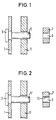
- FIG. 1 a frame-shaped holding part 1 is shown, the several Has openings in which threaded bolts 3 are pressed, of which only one is shown.
- Threaded bolt 3 has a section with a self-tapping External thread 5.
- a nut 7 designed as a stamped part forms this Counterpart to the threaded bolt 3.
- An opening 9 in the nut 7, the has no thread, is in its inner diameter on the outer diameter of the self-tapping thread 5 that the Nut 7 can be screwed onto the external thread 5 and in a thread is cut on the inner wall of the opening 9.
- the holding part 1, which is adapted in its shape to the blowing mouth of an airbag is, the threaded bolt 3 and the nut 7 form a fastener for the gas bag, not shown, as part of a vehicle occupant restraint system.
- the gas bag is in the area of its gas bag mouth by the fastener gas-tight at an outflow opening attached to a gas generator.
- the outlet opening of the gas generator surrounds a flange 11 formed on the gas generator.
- this is in the area of the Gas bag mouth on the flange 11 and the holding part 1 in turn on the Airbag placed in the area of the airbag mouth.
- the threaded bolts 3 extend through corresponding openings in the gas bag and in Flange 11 through.
- the nut 7 is on the threaded bolt 3rd rotated so that an internal thread in the inner wall of the opening 9 is cut.
- the holding part 1 finally presses the gas bag in Area of the gas bag mouth so against the flange 11 that a gas-tight Attachment of the gas bag is reached.
- a nut lock by gluing the nut 7 to the Threaded bolt 3 is not required because between the external thread 5 and the cut internal thread has an increased friction that loosening of the nut 7 prevented.
- the installation of the gas bag can also be done by a mounting device semi or fully automated take place, so far usual Assembly facilities in which nuts with internal thread on one Threaded bolts are screwed on, can be reused, without significant modifications being necessary.
- the embodiment shown in Figure 2 differs from that described with reference to Figure 1 in that the threaded bolt 3 with a self-tapping thread 5 'in the form of a trilobular thread is provided.
- the nut 7 ' comprises a metric internal thread 13. Das Thread 5 'forms the thread 13 plastically when the nut 7' is screwed on around or deforms it only elastically, depending on the dimensions the thread 5 'and 13 to each other.
- By the opposite conventional thread pairings higher force to unscrew the Nut 7 ' also generates an increased loosening torque which ensures that the mother 7 'is secured against automatic loosening. If that Thread 13 is only elastically deformed, the nut 7 'again loosened and then screwed back onto the thread 5 'without that the hedging effect ceases to apply.
- FIG. 3 shows a vehicle occupant restraint system which a gas bag module with a gas bag 13, a gas generator with a Holding part that defines the flange 11 of the gas generator, and one Fastening device for fastening the gas bag module to the vehicle having.
- the fastening means comprises a bolt 3 which is non-rotatable is attached to the flange 11 and a nut 7 screwable thereon.
- a holding part 1 is provided which is inside the gas bag 13 is arranged and for fastening the gas bag 13 to the gas generator 15 serves.
- This holding part is also like the flange 11 with bolts 3 provided that are part of another fastener that like the aforementioned fasteners are constructed.
- the bolts 3 or the nuts 7 comprise a self-tapping or self-tapping thread 5, for cutting, shaping or elastic Deforming a thread in or in the counterpart so that the Nuts are secured against twisting after screwing on.
Landscapes
- Engineering & Computer Science (AREA)
- General Engineering & Computer Science (AREA)
- Mechanical Engineering (AREA)
- Air Bags (AREA)
Abstract
Description
Claims (15)
- Befestigungsmittel bei einem mit einem Gassack ausgestatteten Fahrzeuginsassen-Rückhaltesystem, mit einem Bolzen (3), der drehfest mit einem Halteteil (1) verbunden ist, und einer darauf aufschraubbaren Mutter (7; 7'), dadurch gekennzeichnet, daß der Bolzen (3) oder die Mutter (7; 7') ein selbstschneidendes oder selbstfurchendes Gewinde (5; 5') zum Schneiden, Formen oder elastischen Verformen eines Gewindes in das oder in dem Gegenstück aufweist, so daß die Mutter (7; 7') nach dem Aufschrauben gegen Verdrehen gesichert ist.
- Befestigungsmittel nach Anspruch 1, dadurch gekennzeichnet, daß das Gegenstück zum selbstschneidenden oder selbstfurchenden Gewinde (5) vor dem Aufschrauben der Mutter (7; 7') gewindelos ist.
- Befestigungsmittel nach Anspruch 1 oder 2, dadurch gekennzeichnet, daß die Mutter (7; 7') ein Stanzteil ist.
- Befestigungsmittel nach Anspruch 1 oder 2, dadurch gekennzeichnet, daß die Mutter ein Spritzteil ist.
- Befestigungsmittel nach Anspruch 1 oder 2, dadurch gekennzeichnet, daß die Mutter durch einen Kaltpreßvorgang geformt ist.
- Befestigungsmittel nach einem der vorstehenden Ansprüche, dadurch gekennzeichnet, daß der Bolzen (3) durch Einpressen oder Anformen an dem Halteteil (1) fixiert ist.
- Befestigungsmittel nach einem der vorstehenden Ansprüche, dadurch gekennzeichnet, daß der Bolzen (3) an einem ringförmigen, den Einblasmund eines Gassacks umgebenden Halteteil (1) fixiert ist.
- Verfahren zum Befestigen eines Fahrzeuginsassen-Rückhaltesystems, mit einem Bolzen, der drehfest mit einem Halteteil verbunden ist, dadurch gekennzeichnet, daß zur Befestigung eine Mutter auf den Bolzen gedreht wird und Mutter oder Bolzen ein selbstschneidendes oder selbstfurchendes Gewinde aufweist und in das Gegenstück ein Gewinde schneidet, formt oder elastisch verformt.
- Verfahren nach Anspruch 8, dadurch gekennzeichnet, daß Bolzen und Mutter ein Befestigungsmittel bilden, wie es in den Ansprüchen 2 bis 7 angegeben ist.
- Verfahren nach Anspruch 8, dadruch gekennzeichnet, daß es zum Befestigen eines Gassack-Moduls an einem Fahrzeug dient.
- Verfahren nach Anspruch 8, dadurch gekennzeichnet, daß es zum Befestigen eines Gassacks an einem Gasgenerator dient, wobei das Halteteil am Gassack angreift.
- Fahrzeuginsassen-Rückhaltesystem, mit einem Gassack-Modul, das einen Gassack (13), einen Gasgenerator und ein Befestigungsmittel umfaßt, wobei das Befestigungsmittel ein Halteteil (1), welches am Gassack angreift, aufweist und zur Befestigung des Haltemittels (1) und des Gassacks am Gasgenerator dient, wobei das Befestigungsmittel ferner einen drehfest am Halteteil (1) befestigten Bolzen und eine darauf aufschraubbare Mutter (7) aufweist, dadurch gekennzeichnet, daß der Bolzen (3) oder die Mutter (7) ein selbstschneidendes oder selbstfurchendes Gewinde aufweist, zum Schneiden, Formen oder elastischen Verformen eines Gewindes in das oder in dem Gegenstück, so daß die Mutter (7) nach dem Aufschrauben gegen Verdrehen gesichert ist.
- Fahrzeuginsassen-Rückhaltesystem nach Anspruch 12, dadurch gekennzeichnet, daß das Befestigungsmittel nach einem der Ansprüche 2 bis 7 ausgebildet ist.
- Fahrzeuginsassen-Rückhaltesystem, mit einem Gassack-Modul, das einen Gassack (13), einen Gasgenerator mit einem Flansch (11), welcher ein Halteteil definiert, und ein Befestigungsmittel umfaßt, wobei das Befestigungsmittel ein Halteteil zum Befestigen des Gassack-Moduls am Fahrzeug und ferner einen drehfest am Halteteil (1) befestigten Bolzen (3) und eine darauf aufschraubbare Mutter (7) aufweist, dadurch gekennzeichnet, daß der Bolzen (3) oder die Mutter (7) ein selbstschneidendes oder selbstfurchendes Gewinde (5) zum Schneiden, Formen oder elastischen Verformen eines Gewindes in das oder in dem Gegenstück aufweist, so daß die Mutter (7) nach dem Aufschrauben gegen Verdrehen gesichert ist.
- Fahrzeuginsassen-Rückhaltesystem nach Anspruch 14, dadurch gekennzeichnet, daß das Befestigungsmittel nach einem der Ansprüche 2 bis 7 ausgestaltet ist.
Applications Claiming Priority (2)
| Application Number | Priority Date | Filing Date | Title |
|---|---|---|---|
| DE29614832U DE29614832U1 (de) | 1996-08-26 | 1996-08-26 | Befestigungsmittel bei einem Fahrzeuginsassen-Rückhaltesystem |
| DE29614832U | 1996-08-26 |
Publications (2)
| Publication Number | Publication Date |
|---|---|
| EP0826562A1 true EP0826562A1 (de) | 1998-03-04 |
| EP0826562B1 EP0826562B1 (de) | 2002-10-09 |
Family
ID=8028372
Family Applications (1)
| Application Number | Title | Priority Date | Filing Date |
|---|---|---|---|
| EP97112519A Expired - Lifetime EP0826562B1 (de) | 1996-08-26 | 1997-07-22 | Gassack-Rückhaltesystem mit selbstschneidenden Befestigungsmitteln |
Country Status (6)
| Country | Link |
|---|---|
| US (1) | US6170858B1 (de) |
| EP (1) | EP0826562B1 (de) |
| JP (1) | JPH1076901A (de) |
| KR (1) | KR19980018672A (de) |
| DE (2) | DE29614832U1 (de) |
| ES (1) | ES2116955T3 (de) |
Families Citing this family (18)
| Publication number | Priority date | Publication date | Assignee | Title |
|---|---|---|---|---|
| DE19727063A1 (de) * | 1997-06-25 | 1999-01-07 | Temic Bayern Chem Airbag Gmbh | Gasgenerator |
| DE19809229A1 (de) * | 1998-03-04 | 1999-09-09 | Delphi Automotive Systems Gmbh | Verfahren zum Befestigen eines Anbauteiles |
| DE19816217B4 (de) * | 1998-04-09 | 2005-04-14 | Siemens Ag | Airbagsteuergerät mit zylinderförmigem Gehäuse |
| US6540251B1 (en) * | 2000-03-31 | 2003-04-01 | Illinois Tool Works Inc. | Side airbag retention system and fastener |
| US7004699B2 (en) * | 2001-09-25 | 2006-02-28 | Newfrey Llc | Quick assembly fastening system for plastic parts |
| US6979163B2 (en) * | 2001-10-05 | 2005-12-27 | Illinois Tool Works Inc. | Push-in removable fastener |
| US6817816B2 (en) * | 2002-08-13 | 2004-11-16 | Nd Industries, Inc. | Tapping assist fastening element and method |
| US6953314B2 (en) * | 2003-04-16 | 2005-10-11 | Timothy Magagna | Faucet clamp |
| ES2246119B1 (es) * | 2004-01-26 | 2007-03-16 | I.T.W. España, S.A. | Tuerca de fijacion rapida. |
| US7322273B2 (en) * | 2004-08-13 | 2008-01-29 | The Stanley Works | Piston-piston rod retaining assembly for a hydraulic piston and cylinder unit |
| DE102005020530A1 (de) * | 2005-05-03 | 2006-11-16 | Schaeffler Kg | Verbindungsanordnung zwischen einer Laufrolle und einer Spannvorrichtung |
| DE102006037329B4 (de) * | 2006-08-10 | 2020-01-02 | Andreas Stihl Ag & Co. Kg | Kettenraddeckelanordnung einer handgeführten Kettensäge |
| US20080088119A1 (en) * | 2006-10-13 | 2008-04-17 | Yoshiki Murakami | Passenger constraining apparatus |
| DE102010043589A1 (de) | 2010-11-08 | 2012-05-10 | Baier & Michels Gmbh & Co. Kg | Gewindeerzeugende Mutter, Rohteil zur Herstellung der Mutter und Schraubverbindung aus Mutter und Bolzen |
| CN102809994A (zh) * | 2011-05-30 | 2012-12-05 | 鸿富锦精密工业(深圳)有限公司 | 固定装置 |
| EP2944834B1 (de) * | 2014-05-14 | 2019-03-27 | Volvo Car Corporation | Befestigungsanordnung |
| GB201618301D0 (en) * | 2016-10-28 | 2016-12-14 | Excalibur Screwbolts Ltd | Improvements in or relating to screwbolts |
| US12575049B2 (en) * | 2023-04-27 | 2026-03-10 | Hewlett Packard Enterprise Development Lp | Chassis having a base pan for use with different mounting trays |
Citations (5)
| Publication number | Priority date | Publication date | Assignee | Title |
|---|---|---|---|---|
| JPH02133263A (ja) * | 1988-11-11 | 1990-05-22 | Nippon Plast Co Ltd | ステアリングホイール |
| WO1992021534A1 (en) * | 1991-05-31 | 1992-12-10 | Allied Signal Inc. | Air bag assembly |
| US5484165A (en) * | 1994-08-12 | 1996-01-16 | Trw Vehicle Safety Systems Inc. | Air bag module |
| US5496058A (en) * | 1995-05-17 | 1996-03-05 | Trw Vehicle Safety Systems Inc. | Apparatus with inflator mounting structure |
| US5496059A (en) * | 1994-10-26 | 1996-03-05 | Tip Engineering Group, Inc. | Air bag installation using integrated energy device to form trim piece air bag deployment openings |
Family Cites Families (14)
| Publication number | Priority date | Publication date | Assignee | Title |
|---|---|---|---|---|
| US3985172A (en) * | 1971-06-17 | 1976-10-12 | General Motors Corporation | Panel extruding nut and assembly |
| US3926236A (en) * | 1972-10-30 | 1975-12-16 | Multifastener Corp | Self-fastening nut, panel assembly and apparatus |
| US4083458A (en) * | 1976-04-23 | 1978-04-11 | Young Jr Bruce | Shelf-supporting standards |
| JPS5493531A (en) * | 1977-12-29 | 1979-07-24 | Toyota Motor Corp | Air bag holding device in expansion system crew constraint device |
| US5368327A (en) * | 1989-07-12 | 1994-11-29 | Toyoda Gosei, Co., Ltd. | Air bag device |
| US5176400A (en) * | 1991-07-09 | 1993-01-05 | Textron Inc. | Air bag mounting system |
| US5538377A (en) * | 1994-04-11 | 1996-07-23 | Multifastener Corporation | Enclosed nut retainer |
| US5577762A (en) * | 1995-02-28 | 1996-11-26 | Trw Vehicle Safety Systems Inc. | Attachment structure for use in an inflatable vehicle occupant restraint system |
| DE19528754A1 (de) * | 1995-08-04 | 1997-02-06 | Trw Repa Gmbh | Gassack-Rückhaltemodul |
| EP0776695B1 (de) * | 1995-11-29 | 2002-04-17 | Sulzer Chemtech AG | Packung für eine Gegenstrom-Hochdruckkolonne |
| DE29606724U1 (de) * | 1996-04-15 | 1996-11-14 | Trw Occupant Restraint Systems Gmbh, 73551 Alfdorf | Gassack-Modul für ein Fahrzeug |
| US5613704A (en) * | 1996-04-22 | 1997-03-25 | Trw Vehicle Safety Systems Inc. | Diffuser structure for clamping an inflator in an air bag module |
| DE19651628C2 (de) * | 1996-12-12 | 2001-08-16 | Itw Ateco Gmbh | Verbindung zwischen einer gewindeformenden oder-schneidenden Schraube aus Metall und einem Kunstoffteil |
| US5785348A (en) * | 1997-02-26 | 1998-07-28 | Textron Inc. | Diffusor cup for an inflator device which is used to inflate an airbag in an airbag system |
-
1996
- 1996-08-26 DE DE29614832U patent/DE29614832U1/de not_active Expired - Lifetime
-
1997
- 1997-07-22 ES ES97112519T patent/ES2116955T3/es not_active Expired - Lifetime
- 1997-07-22 EP EP97112519A patent/EP0826562B1/de not_active Expired - Lifetime
- 1997-07-22 DE DE59708423T patent/DE59708423D1/de not_active Expired - Lifetime
- 1997-07-28 US US08/901,756 patent/US6170858B1/en not_active Expired - Fee Related
- 1997-08-14 KR KR1019970038784A patent/KR19980018672A/ko not_active Withdrawn
- 1997-08-25 JP JP9227659A patent/JPH1076901A/ja active Pending
Patent Citations (5)
| Publication number | Priority date | Publication date | Assignee | Title |
|---|---|---|---|---|
| JPH02133263A (ja) * | 1988-11-11 | 1990-05-22 | Nippon Plast Co Ltd | ステアリングホイール |
| WO1992021534A1 (en) * | 1991-05-31 | 1992-12-10 | Allied Signal Inc. | Air bag assembly |
| US5484165A (en) * | 1994-08-12 | 1996-01-16 | Trw Vehicle Safety Systems Inc. | Air bag module |
| US5496059A (en) * | 1994-10-26 | 1996-03-05 | Tip Engineering Group, Inc. | Air bag installation using integrated energy device to form trim piece air bag deployment openings |
| US5496058A (en) * | 1995-05-17 | 1996-03-05 | Trw Vehicle Safety Systems Inc. | Apparatus with inflator mounting structure |
Non-Patent Citations (1)
| Title |
|---|
| PATENT ABSTRACTS OF JAPAN vol. 014, no. 367 (M - 1008) 9 August 1990 (1990-08-09) * |
Also Published As
| Publication number | Publication date |
|---|---|
| US6170858B1 (en) | 2001-01-09 |
| ES2116955T3 (es) | 2003-04-16 |
| EP0826562B1 (de) | 2002-10-09 |
| ES2116955T1 (es) | 1998-08-01 |
| DE29614832U1 (de) | 1997-01-02 |
| JPH1076901A (ja) | 1998-03-24 |
| DE59708423D1 (de) | 2002-11-14 |
| KR19980018672A (ko) | 1998-06-05 |
Similar Documents
| Publication | Publication Date | Title |
|---|---|---|
| EP0826562B1 (de) | Gassack-Rückhaltesystem mit selbstschneidenden Befestigungsmitteln | |
| DE69532542T2 (de) | Einpressmutter | |
| DE69731785T2 (de) | Lüfter und dessen Lüfterantriebseinheit | |
| DE60208103T2 (de) | Mit einer Zierkappe versehene Radmutter und Verfahren zum Zusammensetzen derselben | |
| DE69206225T2 (de) | Erdungsstiftschraube. | |
| DE102011051013A1 (de) | Vorrichtung zur Befestigung eines Anbauteils, zum Beispiel einer Reling, an einer Fahrzeugkarosserie | |
| DE3317924A1 (de) | Fahrzeugradbefestigungseinrichtung | |
| DE3120132A1 (de) | Befestigungselement | |
| EP1101957B1 (de) | Montagescheibe für Fahrzeugteile | |
| DE3506127C2 (de) | ||
| DE20213362U1 (de) | Befestigungsanordnung für eine Heckleuchte | |
| DE69408200T2 (de) | Verfahren zum Befestigen von Luftsackkissen | |
| EP0832790B1 (de) | Einrichtung zum Befestigen eines Gassackmoduls | |
| DE102016209395A1 (de) | Befestigungselement für den Toleranzausgleich | |
| DE19857225B4 (de) | Schraubverbindung | |
| DE3838693A1 (de) | Gewindebildende mutter mit sicherungsabschnitt | |
| DE4220842A1 (de) | Vorrichtung zum Befestigen eines Bauteils an einem zwei beabstandete Bleche aufweisenden Tragteil | |
| EP1612432B1 (de) | Befestigungsanordnung für eine Verkleidung und Befestigungsverfahren | |
| DE102018214627A1 (de) | Fahrzeugtür | |
| DE20005884U1 (de) | Vorrichtung zur lösbaren Befestigung eines Lenkrades auf einer Lenkwelle | |
| EP0795443A1 (de) | Einrichtung zur Befestigung | |
| DE4440240C1 (de) | Radbefestigung für Fahrzeuge | |
| DE3823165C2 (de) | ||
| DE102016222352A1 (de) | Schraubverbindung mit Toleranzausgleich, Kraftfahrzeug mit Schraubverbindung, Verfahren zum Verbinden zweier Bauteile mittels Schraubverbindung und Schraubvorrichtung | |
| WO2022023534A1 (de) | Dachhaubenteil einer führerkabine eines lastkraftfahrzeugs, führerkabine eines lastkraftfahrzeugs und verfahren zum befestigen eines gehäuses eines funktionsteils, insbesondere einer leuchte an einem grundkörper eines dachhaubenteils |
Legal Events
| Date | Code | Title | Description |
|---|---|---|---|
| PUAI | Public reference made under article 153(3) epc to a published international application that has entered the european phase |
Free format text: ORIGINAL CODE: 0009012 |
|
| AK | Designated contracting states |
Kind code of ref document: A1 Designated state(s): DE ES FR GB IT |
|
| AX | Request for extension of the european patent |
Free format text: AL;LT;LV;RO;SI |
|
| GBC | Gb: translation of claims filed (gb section 78(7)/1977) | ||
| RAP1 | Party data changed (applicant data changed or rights of an application transferred) |
Owner name: TRW OCCUPANT RESTRAINT SYSTEMS GMBH & CO. KG |
|
| REG | Reference to a national code |
Ref country code: ES Ref legal event code: BA2A Ref document number: 2116955 Country of ref document: ES Kind code of ref document: T1 |
|
| EL | Fr: translation of claims filed | ||
| 17P | Request for examination filed |
Effective date: 19980817 |
|
| AKX | Designation fees paid |
Free format text: DE ES FR GB IT |
|
| RBV | Designated contracting states (corrected) |
Designated state(s): DE ES FR GB IT |
|
| 17Q | First examination report despatched |
Effective date: 20010309 |
|
| GRAG | Despatch of communication of intention to grant |
Free format text: ORIGINAL CODE: EPIDOS AGRA |
|
| GRAG | Despatch of communication of intention to grant |
Free format text: ORIGINAL CODE: EPIDOS AGRA |
|
| GRAH | Despatch of communication of intention to grant a patent |
Free format text: ORIGINAL CODE: EPIDOS IGRA |
|
| GRAG | Despatch of communication of intention to grant |
Free format text: ORIGINAL CODE: EPIDOS AGRA |
|
| GRAH | Despatch of communication of intention to grant a patent |
Free format text: ORIGINAL CODE: EPIDOS IGRA |
|
| GRAH | Despatch of communication of intention to grant a patent |
Free format text: ORIGINAL CODE: EPIDOS IGRA |
|
| GRAA | (expected) grant |
Free format text: ORIGINAL CODE: 0009210 |
|
| AK | Designated contracting states |
Kind code of ref document: B1 Designated state(s): DE ES FR GB IT |
|
| REG | Reference to a national code |
Ref country code: GB Ref legal event code: FG4D Free format text: NOT ENGLISH |
|
| REF | Corresponds to: |
Ref document number: 59708423 Country of ref document: DE Date of ref document: 20021114 |
|
| GBT | Gb: translation of ep patent filed (gb section 77(6)(a)/1977) |
Effective date: 20030108 |
|
| ET | Fr: translation filed | ||
| REG | Reference to a national code |
Ref country code: ES Ref legal event code: FG2A Ref document number: 2116955 Country of ref document: ES Kind code of ref document: T3 |
|
| PGFP | Annual fee paid to national office [announced via postgrant information from national office to epo] |
Ref country code: GB Payment date: 20030612 Year of fee payment: 7 |
|
| PLBE | No opposition filed within time limit |
Free format text: ORIGINAL CODE: 0009261 |
|
| STAA | Information on the status of an ep patent application or granted ep patent |
Free format text: STATUS: NO OPPOSITION FILED WITHIN TIME LIMIT |
|
| 26N | No opposition filed |
Effective date: 20030710 |
|
| PG25 | Lapsed in a contracting state [announced via postgrant information from national office to epo] |
Ref country code: GB Free format text: LAPSE BECAUSE OF NON-PAYMENT OF DUE FEES Effective date: 20040722 |
|
| GBPC | Gb: european patent ceased through non-payment of renewal fee |
Effective date: 20040722 |
|
| PGFP | Annual fee paid to national office [announced via postgrant information from national office to epo] |
Ref country code: ES Payment date: 20080130 Year of fee payment: 11 |
|
| PGFP | Annual fee paid to national office [announced via postgrant information from national office to epo] |
Ref country code: IT Payment date: 20080124 Year of fee payment: 11 |
|
| PGFP | Annual fee paid to national office [announced via postgrant information from national office to epo] |
Ref country code: FR Payment date: 20080116 Year of fee payment: 11 |
|
| REG | Reference to a national code |
Ref country code: FR Ref legal event code: ST Effective date: 20090331 |
|
| PG25 | Lapsed in a contracting state [announced via postgrant information from national office to epo] |
Ref country code: IT Free format text: LAPSE BECAUSE OF NON-PAYMENT OF DUE FEES Effective date: 20080722 Ref country code: FR Free format text: LAPSE BECAUSE OF NON-PAYMENT OF DUE FEES Effective date: 20080731 |
|
| REG | Reference to a national code |
Ref country code: ES Ref legal event code: FD2A Effective date: 20080723 |
|
| PG25 | Lapsed in a contracting state [announced via postgrant information from national office to epo] |
Ref country code: ES Free format text: LAPSE BECAUSE OF NON-PAYMENT OF DUE FEES Effective date: 20080723 |
|
| PGFP | Annual fee paid to national office [announced via postgrant information from national office to epo] |
Ref country code: DE Payment date: 20110731 Year of fee payment: 15 |
|
| PG25 | Lapsed in a contracting state [announced via postgrant information from national office to epo] |
Ref country code: DE Free format text: LAPSE BECAUSE OF NON-PAYMENT OF DUE FEES Effective date: 20130201 |
|
| REG | Reference to a national code |
Ref country code: DE Ref legal event code: R119 Ref document number: 59708423 Country of ref document: DE Effective date: 20130201 |