EP0826575A2 - Dispositif pour alimentation de pression électro-hydraulique pour une direction assistée d'un véhicule automobile - Google Patents
Dispositif pour alimentation de pression électro-hydraulique pour une direction assistée d'un véhicule automobile Download PDFInfo
- Publication number
- EP0826575A2 EP0826575A2 EP97113368A EP97113368A EP0826575A2 EP 0826575 A2 EP0826575 A2 EP 0826575A2 EP 97113368 A EP97113368 A EP 97113368A EP 97113368 A EP97113368 A EP 97113368A EP 0826575 A2 EP0826575 A2 EP 0826575A2
- Authority
- EP
- European Patent Office
- Prior art keywords
- electric motor
- pump
- adapter
- shaft
- motor
- Prior art date
- Legal status (The legal status is an assumption and is not a legal conclusion. Google has not performed a legal analysis and makes no representation as to the accuracy of the status listed.)
- Granted
Links
Images


Classifications
-
- B—PERFORMING OPERATIONS; TRANSPORTING
- B62—LAND VEHICLES FOR TRAVELLING OTHERWISE THAN ON RAILS
- B62D—MOTOR VEHICLES; TRAILERS
- B62D5/00—Power-assisted or power-driven steering
- B62D5/06—Power-assisted or power-driven steering fluid, i.e. using a pressurised fluid for most or all the force required for steering a vehicle
- B62D5/062—Details, component parts
- B62D5/064—Pump driven independently from vehicle engine, e.g. electric driven pump
Definitions
- the invention relates to an arrangement for an electro-hydraulic pressure supply for an auxiliary device in a motor vehicle, in which by a pump driven by an electric motor, which is filled with oil Container is arranged, the oil through an outlet opening to the auxiliary device conducts and from the auxiliary device via a return opening is returned to the container, with a shaft of the electric motor is coupled to a shaft of the pump.
- the pump is arranged in an oil tank, the pump shaft in two Pump bearings is held.
- the shaft of the electric motor is also in two motor bearings held.
- the invention is therefore based on the object of an arrangement for specify electrohydraulic pressure supply for auxiliary equipment that can also be used in small structural units.
- the object is achieved in that the shaft of the electric motor and the shaft of the pump are coupled in a central bearing.
- the invention has the advantage that a space-saving electrohydraulic Pump system is created in which no radial forces from the motor to the Pump can be transferred. This is a reliable way of working Guaranteed aggregate. In addition, there is an optimal and short hose installation for the hydraulics, since the unit is no longer from the installation location of the Drive motor depends.
- the central bearing is advantageously arranged in an adapter, which connects the electric motor to the fuel tank. This will make a warehouse saved because the electric motor and pump share this bearing.
- the design can be further reduced if the central bearing on the the adapter associated side of the electric motor is arranged.
- motor electronics are on the outer wall of the adapter thermally connected to it.
- the motor electronics are in the electric motor itself arranged.
- the engine electronics are a hybrid component which is arranged on the side of the electric motor facing the adapter is and is thermally connected to the adapter.
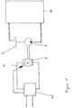
- FIG 1 an electro-hydraulic pump supply is shown schematically, in which a steering support via the oil pressure in a circulation system 13 is realized.
- the steering forces even with a small gear ratio to keep it low, the steering work is supported by pressure oil, which is transported in a closed cycle.
- the function of a such power steering is well known and therefore does not have to go further to be discribed.
- a pump 1 is driven by an electric motor 3 operated.
- a speed detection device 14 detects the engine speed n of the electric motor 3 and forwards the signal to motor electronics 11.
- FIG. 2 shows the electrohydraulic pump arrangement according to the invention shown as they are used in an auxiliary steering system in a motor vehicle finds.
- a gear pump 1 is arranged in a plastic tank 2 filled with oil, which has a dipstick 12 for determining the tank content.
- To the Plastic tank 2 connects to an adapter 6, which the electric motor 3 with connects the plastic tank 2.
- the adapter 6 is part of the tank 2 and is designed to be open to it, so that the oil completely fills the adapter 6.
- Flow slots not shown, becomes the one moved by the pump 1 Oil is transported to an outlet opening 8 on the adapter 6 and into a line system pressed, which is connected to the steering.
- a return opening 9 is provided for pressure-free return of the pressure oil from the steering. So can the oil from the pump 1 can be transported to the steering again.
- the pump 1 is driven by the electric motor 3.
- the central bearing 7 is arranged in a space-saving manner in the adapter 6.
- the pump 1 has a further bearing 7a and the electric motor another camp 7b.
- the plastic tank 2, adapter 6 and motor 3 form a cylindrical shape on the outside Unit.
- Power electronics 11 are attached to the outer wall of the adapter 6 in such a way that the heat generated by the power electronics 11 from the im Adapters located oil is recorded, the oil is transported in the motor vehicle and is cooled there.
- the power electronics 11 is a thick-film hybrid component, the circuit board with its electrically isolated and facing away from the components 16 Bears against the wall of the adapter 6.
- the hybrid component 11 has a circular shape Base area that corresponds to the base area of the electric motor and the adapter.
- the hybrid component 11 is on the adapter 6 on the electric motor facing side mounted so that the circuit board side not carrying any components rests directly on the bottom of the adapter 6 which has just been designed and thereby the heat dissipation is guaranteed.
- the hybrid component 11 is in a recess of the electric motor sunk.
- the motor shaft 5 through a central opening 15 of the hybrid component ( Figure 3).
Landscapes
- Engineering & Computer Science (AREA)
- Chemical & Material Sciences (AREA)
- Combustion & Propulsion (AREA)
- Transportation (AREA)
- Mechanical Engineering (AREA)
- Motor Or Generator Cooling System (AREA)
- Details Of Reciprocating Pumps (AREA)
- Auxiliary Drives, Propulsion Controls, And Safety Devices (AREA)
- Hybrid Electric Vehicles (AREA)
Applications Claiming Priority (2)
| Application Number | Priority Date | Filing Date | Title |
|---|---|---|---|
| DE19635411 | 1996-08-31 | ||
| DE19635411A DE19635411A1 (de) | 1996-08-31 | 1996-08-31 | Anordnung für eine elektrohydraulische Druckversorgung für eine Hilfskrafteinrichtung in einem Kraftfahrzeug |
Publications (3)
| Publication Number | Publication Date |
|---|---|
| EP0826575A2 true EP0826575A2 (fr) | 1998-03-04 |
| EP0826575A3 EP0826575A3 (fr) | 2000-08-16 |
| EP0826575B1 EP0826575B1 (fr) | 2005-10-26 |
Family
ID=7804306
Family Applications (1)
| Application Number | Title | Priority Date | Filing Date |
|---|---|---|---|
| EP97113368A Expired - Lifetime EP0826575B1 (fr) | 1996-08-31 | 1997-08-02 | Dispositif pour alimentation de pression électro-hydraulique pour une direction assistée d'un véhicule automobile |
Country Status (3)
| Country | Link |
|---|---|
| US (1) | US5953913A (fr) |
| EP (1) | EP0826575B1 (fr) |
| DE (2) | DE19635411A1 (fr) |
Cited By (1)
| Publication number | Priority date | Publication date | Assignee | Title |
|---|---|---|---|---|
| WO2010057485A1 (fr) * | 2008-11-20 | 2010-05-27 | Wilhelm Karmann Gmbh I. I. | Groupe hydraulique |
Families Citing this family (5)
| Publication number | Priority date | Publication date | Assignee | Title |
|---|---|---|---|---|
| DE19856096A1 (de) | 1997-12-23 | 1999-06-24 | Mannesmann Rexroth Ag | Antrieb für eine Pumpe |
| DE10028957C2 (de) * | 2000-06-16 | 2002-07-11 | Lukas Hydraulik Gmbh & Co Kg | Tragbare Hydraulikpumpeneinheit |
| DE202004009057U1 (de) * | 2004-06-08 | 2004-10-14 | Trw Automotive Gmbh | Motor/Pumpen-Aggregat |
| CN104153987B (zh) * | 2014-08-21 | 2016-04-27 | 天津市通洁高压泵制造有限公司 | 一种自给式动力端润滑油循环冷却系统 |
| DE102017127675B4 (de) * | 2017-11-23 | 2023-03-23 | HAWE Altenstadt Holding GmbH | Hydraulische Druckversorgungseinheit |
Family Cites Families (11)
| Publication number | Priority date | Publication date | Assignee | Title |
|---|---|---|---|---|
| US2669187A (en) * | 1949-04-27 | 1954-02-16 | Guyer Ernest | Glandless pump and motor unit |
| DE2447515A1 (de) * | 1973-10-08 | 1975-04-24 | Apv Co Ltd | Drehmaschine |
| JP2503574B2 (ja) * | 1988-03-10 | 1996-06-05 | トヨタ自動車株式会社 | 車両用動力舵取装置 |
| DE4231784A1 (de) * | 1991-06-22 | 1994-03-24 | Teves Gmbh Alfred | Elektromotorisch angetriebene Hydraulikpumpe |
| DE4120665A1 (de) * | 1991-06-22 | 1992-12-24 | Teves Gmbh Alfred | Elektromotorisch angetriebene hydraulikpumpe |
| US5151016A (en) * | 1991-12-05 | 1992-09-29 | Her Tser W | Liquid pump responsive to temperature |
| DE4320692A1 (de) * | 1993-06-22 | 1995-01-05 | Rudolf Pickel | Hydraulisches Pumpenaggregat |
| US5378121A (en) * | 1993-07-28 | 1995-01-03 | Hackett; William F. | Pump with fluid bearing |
| AU682393B2 (en) * | 1993-10-13 | 1997-10-02 | Ebara Corporation | Motor stator assembly and full-circumferential flow pump employing such motor stator assembly |
| DE29606135U1 (de) * | 1996-04-02 | 1996-08-22 | Speck Pumpenfabrik Walter Spec | Galvanisch getrennte Pumpe |
| DE29609701U1 (de) * | 1996-05-31 | 1996-08-22 | Heilmeier & Weinlein Fabrik für Oel-Hydraulik GmbH & Co KG, 81673 München | Elektrohydraulisches Motorpumpenaggregat |
-
1996
- 1996-08-31 DE DE19635411A patent/DE19635411A1/de not_active Ceased
-
1997
- 1997-08-02 DE DE59712455T patent/DE59712455D1/de not_active Expired - Fee Related
- 1997-08-02 EP EP97113368A patent/EP0826575B1/fr not_active Expired - Lifetime
- 1997-08-22 US US08/916,566 patent/US5953913A/en not_active Expired - Fee Related
Cited By (1)
| Publication number | Priority date | Publication date | Assignee | Title |
|---|---|---|---|---|
| WO2010057485A1 (fr) * | 2008-11-20 | 2010-05-27 | Wilhelm Karmann Gmbh I. I. | Groupe hydraulique |
Also Published As
| Publication number | Publication date |
|---|---|
| EP0826575A3 (fr) | 2000-08-16 |
| DE59712455D1 (de) | 2005-12-01 |
| EP0826575B1 (fr) | 2005-10-26 |
| US5953913A (en) | 1999-09-21 |
| DE19635411A1 (de) | 1998-03-05 |
Similar Documents
| Publication | Publication Date | Title |
|---|---|---|
| DE19710931B4 (de) | Automatikgetriebe mit integrierter Steuerungselektronik | |
| DE19821794A1 (de) | Motorpumpenaggregat | |
| DE102017208390A1 (de) | Hydraulikaggregat einer Schlupfregelung einer Fahrzeugbremsanlage mit einem Hydraulikblock und einem Motorblock | |
| DE102004060417B4 (de) | Kompakter Schraubenkompressor zum mobilen Einsatz in einem Fahrzeug | |
| DE102016215184B4 (de) | Hybridantrieb | |
| EP0826575A2 (fr) | Dispositif pour alimentation de pression électro-hydraulique pour une direction assistée d'un véhicule automobile | |
| DE19641557A1 (de) | Antriebseinheit mit einem Motor, einem Getriebe und einem Kühlmittelkreislauf | |
| DE102004058261A1 (de) | Pumpe mit zwei Pumpstufen und Verfahren zur Ölversorgung eines Fahrzeuggetriebes und einer dem Fahrzeuggetriebe zugehörigen Kupplungsanordnung | |
| DE102018106799A1 (de) | Elektrischer Antrieb | |
| WO2019185261A1 (fr) | Système de prise de force | |
| DE19623679C5 (de) | Antriebs-Baugruppe mit einem Retarder und einem Wärmetauscher | |
| EP0289606B1 (fr) | Dispositif de lubrification de roulements hydrodynamiques | |
| DE19744599A1 (de) | Hydraulikkreislauf | |
| WO2024255965A2 (fr) | Boîtier multifonction et chaîne cinématique d'essieu électrique | |
| WO2009143916A1 (fr) | Dispositif pour faire fonctionner un groupe auxiliaire d’un véhicule à moteur, en particulier d’un véhicule utilitaire | |
| DE102019205610A1 (de) | Elektrische ölpumpenvorrichtung für ein fahrzeug | |
| EP0460464A2 (fr) | Véhicule comportant un ventilateur pour le système de refroidissement du moteur thermique ainsi qu'une servo-direction du type à centre ouvert | |
| DE102018112455B3 (de) | System, umfassend eine Kühlmittelpumpe für ein Kraftfahrzeug und eine Antriebsvorrichtung für die Kühlmittelpumpe | |
| DE102005022454A1 (de) | Pumpenantrieb für die Pumpe eines Retarders | |
| DE102022134334B4 (de) | Motorgehäuse mit Fluidsteuerung | |
| DE202005020634U1 (de) | Elektrisches Antriebssystem für Flurförderzeuge | |
| DE3124040A1 (de) | Antrieb fuer eine foerderpumpe einer hydrostatischen kraftuebertragung | |
| EP1248920B1 (fr) | Mecanisme de derivation de puissance | |
| DE102024112431A1 (de) | Multifunktionsmodul | |
| CH634783A5 (en) | Sound-insulated pumping unit on a tanker vehicle |
Legal Events
| Date | Code | Title | Description |
|---|---|---|---|
| PUAI | Public reference made under article 153(3) epc to a published international application that has entered the european phase |
Free format text: ORIGINAL CODE: 0009012 |
|
| AK | Designated contracting states |
Kind code of ref document: A2 Designated state(s): DE FR GB |
|
| AX | Request for extension of the european patent |
Free format text: AL;LT;LV;RO;SI |
|
| PUAL | Search report despatched |
Free format text: ORIGINAL CODE: 0009013 |
|
| RIC1 | Information provided on ipc code assigned before grant |
Free format text: 7B 62D 5/06 A, 7F 04D 13/02 B |
|
| AK | Designated contracting states |
Kind code of ref document: A3 Designated state(s): AT BE CH DE DK ES FI FR GB GR IE IT LI LU MC NL PT SE |
|
| AX | Request for extension of the european patent |
Free format text: AL;LT;LV;RO;SI |
|
| 17P | Request for examination filed |
Effective date: 20000714 |
|
| AKX | Designation fees paid |
Free format text: DE FR GB |
|
| RAP1 | Party data changed (applicant data changed or rights of an application transferred) |
Owner name: SIEMENS AKTIENGESELLSCHAFT |
|
| 17Q | First examination report despatched |
Effective date: 20020426 |
|
| GRAP | Despatch of communication of intention to grant a patent |
Free format text: ORIGINAL CODE: EPIDOSNIGR1 |
|
| GRAS | Grant fee paid |
Free format text: ORIGINAL CODE: EPIDOSNIGR3 |
|
| GRAA | (expected) grant |
Free format text: ORIGINAL CODE: 0009210 |
|
| AK | Designated contracting states |
Kind code of ref document: B1 Designated state(s): DE FR GB |
|
| REG | Reference to a national code |
Ref country code: GB Ref legal event code: FG4D Free format text: NOT ENGLISH |
|
| REF | Corresponds to: |
Ref document number: 59712455 Country of ref document: DE Date of ref document: 20051201 Kind code of ref document: P |
|
| GBT | Gb: translation of ep patent filed (gb section 77(6)(a)/1977) |
Effective date: 20051111 |
|
| ET | Fr: translation filed | ||
| PLBE | No opposition filed within time limit |
Free format text: ORIGINAL CODE: 0009261 |
|
| STAA | Information on the status of an ep patent application or granted ep patent |
Free format text: STATUS: NO OPPOSITION FILED WITHIN TIME LIMIT |
|
| 26N | No opposition filed |
Effective date: 20060727 |
|
| PGFP | Annual fee paid to national office [announced via postgrant information from national office to epo] |
Ref country code: DE Payment date: 20080822 Year of fee payment: 12 |
|
| PGFP | Annual fee paid to national office [announced via postgrant information from national office to epo] |
Ref country code: FR Payment date: 20080813 Year of fee payment: 12 |
|
| PGFP | Annual fee paid to national office [announced via postgrant information from national office to epo] |
Ref country code: GB Payment date: 20080821 Year of fee payment: 12 |
|
| GBPC | Gb: european patent ceased through non-payment of renewal fee |
Effective date: 20090802 |
|
| REG | Reference to a national code |
Ref country code: FR Ref legal event code: ST Effective date: 20100430 |
|
| PG25 | Lapsed in a contracting state [announced via postgrant information from national office to epo] |
Ref country code: FR Free format text: LAPSE BECAUSE OF NON-PAYMENT OF DUE FEES Effective date: 20090831 Ref country code: DE Free format text: LAPSE BECAUSE OF NON-PAYMENT OF DUE FEES Effective date: 20100302 |
|
| PG25 | Lapsed in a contracting state [announced via postgrant information from national office to epo] |
Ref country code: GB Free format text: LAPSE BECAUSE OF NON-PAYMENT OF DUE FEES Effective date: 20090802 |