EP0826874A2 - Dispositif de refroidissement de carburant pour moteur à combustion - Google Patents
Dispositif de refroidissement de carburant pour moteur à combustion Download PDFInfo
- Publication number
- EP0826874A2 EP0826874A2 EP97113808A EP97113808A EP0826874A2 EP 0826874 A2 EP0826874 A2 EP 0826874A2 EP 97113808 A EP97113808 A EP 97113808A EP 97113808 A EP97113808 A EP 97113808A EP 0826874 A2 EP0826874 A2 EP 0826874A2
- Authority
- EP
- European Patent Office
- Prior art keywords
- heat exchanger
- fuel
- line
- exchanger body
- combustion engine
- Prior art date
- Legal status (The legal status is an assumption and is not a legal conclusion. Google has not performed a legal analysis and makes no representation as to the accuracy of the status listed.)
- Granted
Links
- 239000000446 fuel Substances 0.000 title claims abstract description 39
- 238000002485 combustion reaction Methods 0.000 title claims abstract description 25
- 238000001816 cooling Methods 0.000 title claims description 7
- 239000002828 fuel tank Substances 0.000 description 5
- 238000002347 injection Methods 0.000 description 3
- 239000007924 injection Substances 0.000 description 3
- 238000000034 method Methods 0.000 description 2
- XAGFODPZIPBFFR-UHFFFAOYSA-N aluminium Chemical compound [Al] XAGFODPZIPBFFR-UHFFFAOYSA-N 0.000 description 1
- 229910052782 aluminium Inorganic materials 0.000 description 1
- 238000010276 construction Methods 0.000 description 1
- 230000001419 dependent effect Effects 0.000 description 1
- 230000000694 effects Effects 0.000 description 1
- 238000001914 filtration Methods 0.000 description 1
- 238000011031 large-scale manufacturing process Methods 0.000 description 1
- 239000000463 material Substances 0.000 description 1
Images


Classifications
-
- F—MECHANICAL ENGINEERING; LIGHTING; HEATING; WEAPONS; BLASTING
- F28—HEAT EXCHANGE IN GENERAL
- F28D—HEAT-EXCHANGE APPARATUS, NOT PROVIDED FOR IN ANOTHER SUBCLASS, IN WHICH THE HEAT-EXCHANGE MEDIA DO NOT COME INTO DIRECT CONTACT
- F28D1/00—Heat-exchange apparatus having stationary conduit assemblies for one heat-exchange medium only, the media being in contact with different sides of the conduit wall, in which the other heat-exchange medium is a large body of fluid, e.g. domestic or motor car radiators
- F28D1/02—Heat-exchange apparatus having stationary conduit assemblies for one heat-exchange medium only, the media being in contact with different sides of the conduit wall, in which the other heat-exchange medium is a large body of fluid, e.g. domestic or motor car radiators with heat-exchange conduits immersed in the body of fluid
- F28D1/0246—Heat-exchange apparatus having stationary conduit assemblies for one heat-exchange medium only, the media being in contact with different sides of the conduit wall, in which the other heat-exchange medium is a large body of fluid, e.g. domestic or motor car radiators with heat-exchange conduits immersed in the body of fluid heat-exchange elements having several adjacent conduits forming a whole, e.g. blocks
-
- F—MECHANICAL ENGINEERING; LIGHTING; HEATING; WEAPONS; BLASTING
- F02—COMBUSTION ENGINES; HOT-GAS OR COMBUSTION-PRODUCT ENGINE PLANTS
- F02M—SUPPLYING COMBUSTION ENGINES IN GENERAL WITH COMBUSTIBLE MIXTURES OR CONSTITUENTS THEREOF
- F02M31/00—Apparatus for thermally treating combustion-air, fuel, or fuel-air mixture
- F02M31/20—Apparatus for thermally treating combustion-air, fuel, or fuel-air mixture for cooling
-
- F—MECHANICAL ENGINEERING; LIGHTING; HEATING; WEAPONS; BLASTING
- F28—HEAT EXCHANGE IN GENERAL
- F28F—DETAILS OF HEAT-EXCHANGE AND HEAT-TRANSFER APPARATUS, OF GENERAL APPLICATION
- F28F1/00—Tubular elements; Assemblies of tubular elements
- F28F1/02—Tubular elements of cross-section which is non-circular
- F28F1/022—Tubular elements of cross-section which is non-circular with multiple channels
-
- F—MECHANICAL ENGINEERING; LIGHTING; HEATING; WEAPONS; BLASTING
- F28—HEAT EXCHANGE IN GENERAL
- F28F—DETAILS OF HEAT-EXCHANGE AND HEAT-TRANSFER APPARATUS, OF GENERAL APPLICATION
- F28F1/00—Tubular elements; Assemblies of tubular elements
- F28F1/10—Tubular elements and assemblies thereof with means for increasing heat-transfer area, e.g. with fins, with projections, with recesses
- F28F1/42—Tubular elements and assemblies thereof with means for increasing heat-transfer area, e.g. with fins, with projections, with recesses the means being both outside and inside the tubular element
-
- F—MECHANICAL ENGINEERING; LIGHTING; HEATING; WEAPONS; BLASTING
- F28—HEAT EXCHANGE IN GENERAL
- F28F—DETAILS OF HEAT-EXCHANGE AND HEAT-TRANSFER APPARATUS, OF GENERAL APPLICATION
- F28F3/00—Plate-like or laminated elements; Assemblies of plate-like or laminated elements
- F28F3/12—Elements constructed in the shape of a hollow panel, e.g. with channels
-
- F—MECHANICAL ENGINEERING; LIGHTING; HEATING; WEAPONS; BLASTING
- F28—HEAT EXCHANGE IN GENERAL
- F28F—DETAILS OF HEAT-EXCHANGE AND HEAT-TRANSFER APPARATUS, OF GENERAL APPLICATION
- F28F2250/00—Arrangements for modifying the flow of the heat exchange media, e.g. flow guiding means; Particular flow patterns
- F28F2250/04—Communication passages between channels
-
- Y—GENERAL TAGGING OF NEW TECHNOLOGICAL DEVELOPMENTS; GENERAL TAGGING OF CROSS-SECTIONAL TECHNOLOGIES SPANNING OVER SEVERAL SECTIONS OF THE IPC; TECHNICAL SUBJECTS COVERED BY FORMER USPC CROSS-REFERENCE ART COLLECTIONS [XRACs] AND DIGESTS
- Y02—TECHNOLOGIES OR APPLICATIONS FOR MITIGATION OR ADAPTATION AGAINST CLIMATE CHANGE
- Y02T—CLIMATE CHANGE MITIGATION TECHNOLOGIES RELATED TO TRANSPORTATION
- Y02T10/00—Road transport of goods or passengers
- Y02T10/10—Internal combustion engine [ICE] based vehicles
- Y02T10/12—Improving ICE efficiencies
Definitions
- the invention relates to a device for fuel cooling on an internal combustion engine according to the preamble of claim 1.
- the first two documents have modest heat exchange surfaces and each cool in the fuel supply, where the temperatures are comparatively low anyway.
- the next-mentioned document uses existing blowers to promote an air flow, the routing of the fuel for the fuel is complicated and unnecessary, not crash-proof, and also promotes an already strongly warmed air flow through the cooler, particularly in intense sunlight.
- the invention has for its object a device for cooling an internal combustion engine to create fuel supplied by an increased heat exchange improved cooling achieved.
- the invention provides that a separate inside the housing through which the intake air flows Heat exchanger body is arranged, which is switched in series in the fuel-carrying line is, d. H. in the course of which the fuel flows.
- the outer Surface of this heat exchanger body at least partially from that of the internal combustion engine acted upon by intake air supplied through the housing.
- This type of arrangement advantageously allows the possibility of a greatly increased Heat transfer from the heated fuel to the comparatively cool, the internal combustion engine supplied intake air given.
- this measure can be improved by further measures, that is, the achievable temperature reduction can be increased.
- the heat exchanger body can be provided, at least in sections, on its outer surface with projections that increase the heat transfer, for example in the form of ribs.
- the line section of the fuel-carrying line running inside the heat exchanger body can be curved to extend the flow path and the wall of this line can in turn be provided with fins that increase the heat transfer.
- the heat exchanger body is preferably of modular construction, with, for example two plate-like components are provided.
- one of the components of the Wear air-loaded ribs on one side and on the opposite Side, the fuel line can be designed as an initially open channel, which in particular an inexpensive manufacturability of this component granted.
- the other component can be designed as a base plate closing the channel or, for particularly high requirements, be a mirror image of the first-mentioned component.
- the gutter can expand into labyrinth chambers, which are underneath one another communicate through connecting holes.
- the one for heat exchange available surface and wetted by the fuel increases, whereby if necessary, the depth of the channel can be reduced.
- the modular heat exchanger body consist of several layers, each Parts of the fuel line are formed within the individual, plate-like layers are.
- the heat exchanger body can be an extruded profile be trained, which in turn an inexpensive large-scale production enables.
- This can also be provided with cooling fins on its outer surface be.
- the fuel line can in turn be bent several times within the extruded profile run meandering, the formed in the extruded profile, the Fuel-carrying profile chambers in turn increase the heat transfer Ribs can be provided.
- the materials for the heat exchanger body come in particular with high Thermal conductivity into consideration, e.g. B. on an aluminum basis.
- Intake air flow is preferably provided that the intake air and housing receiving the heat exchanger body as an air filter housing of the internal combustion engine is formed, with a space-saving arrangement by a location of the Heat exchanger body found downstream of the air filter integrated in the housing has been.
- the arrangement of the heat exchanger body is preferred in the course of the Excess cylinder head promoted and not required there for the current injection process Arrange fuel return line. In this are the ones that occur Fuel temperatures particularly high, so that a clear temperature gradient compared the comparatively cool intake air is present.
- An internal combustion engine (not shown) installed in a motor vehicle has, in the course of an air intake path for combustion air supplied to the internal combustion engine, a housing 1 designed as an air filter housing.
- a housing 1 designed as an air filter housing.
- raw air is sucked in via an air inlet 2 arranged on the side of the housing 1 and passed through an air filter (not shown) arranged in a lower housing part 3.
- the cleaned filter air flows into an essentially roof-shaped upper housing part 4, which is provided with an outflow opening 5, which is connected in a manner not shown to the intake ducts of the internal combustion engine.
- a fuel-carrying line 6 is assigned to the internal combustion engine is guided inside the housing 1 through which the intake air flows.
- Fuel necessary for the operation of the internal combustion engine is known per se Way with a feed pump from a fuel tank in the cylinder head of the internal combustion engine arranged injectors promoted. Excess at the current one Injection process of fuel that is not required heats up in the fuel already described above Wise. This heated fuel is returned to the fuel tank via a return fed. The line 6 is part of this return, so that heated, backflow Fuel reaches the interior of the housing 1 via the inlet connection 8, and there one Heat exchanger body 10 to be described in more detail is supplied. After that The cooled fuel flows through the outflow connector 9 back into the Fuel tank.
- this heat exchanger body 10 is formed from two plate-like components 11 and 12, one component 11 being provided on one of its sides 14 with the heat transfer-increasing projections 13 designed as ribs.
- the parallel, other side 15 of this component 11 has an initially open channel 16, which becomes a closed channel 17 as part of the line 6 by subsequent assembly of the second component 12.
- the heated, returning fuel passes through the inlet connection 8 to an infeed point 18 and from there enters the channel 17, which is curved several times and is formed in a meandering manner in an inner region.
- An outflow point 19 can be connected to the outflow connection 9 or, in the case of increased demands on the temperature reduction to be achieved, can cooperate with further, sandwich-like and plate-like components.
- the heat exchanger body 10 can also consist of two identical components 11. The arrangement of the heat exchanger body 10 within the air filter housing, in connection with the large outer surface provided by the projections 13, ensures a sharp reduction in the fuel temperature during operation of the internal combustion engine due to the comparatively high, constantly promoted intake air flow.
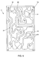
- a plurality of labyrinth chambers 20 can be arranged, which one another through transverse channels 21 communicate.
- the individual labyrinth chambers 20 can have several transverse channels 21 be assigned. The entry of the fuel in turn takes place via the feed point 18, from which the fuel then over several flow paths to Outflow point 19 arrives.
- the heat exchanger body 10 can, as shown in FIG Extruded profile 22 may be formed within which, as part of the line 6, fuel-carrying, interconnected profile chambers 23 are formed, which function correspond to the previously described channel 17.
- the outer surface of the extruded profile 22 also be provided with rib-like projections 13 and the walls the profile chambers 23 can also be provided with ribs 24.
- the heat exchanger body can also in any other housing through which intake air flows, e.g. B. one Intake hose, an air scoop or a shunt resonator may be arranged, however offers the arrangement shown within an already existing and required Volume of the air filter housing with respect to the space required considerable advantages.
Landscapes
- Engineering & Computer Science (AREA)
- Mechanical Engineering (AREA)
- General Engineering & Computer Science (AREA)
- Physics & Mathematics (AREA)
- Thermal Sciences (AREA)
- Chemical & Material Sciences (AREA)
- Combustion & Propulsion (AREA)
- Geometry (AREA)
- Fuel-Injection Apparatus (AREA)
- Heat-Exchange Devices With Radiators And Conduit Assemblies (AREA)
Applications Claiming Priority (2)
| Application Number | Priority Date | Filing Date | Title |
|---|---|---|---|
| DE19635168 | 1996-08-30 | ||
| DE19635168 | 1996-08-30 |
Publications (3)
| Publication Number | Publication Date |
|---|---|
| EP0826874A2 true EP0826874A2 (fr) | 1998-03-04 |
| EP0826874A3 EP0826874A3 (fr) | 1998-08-19 |
| EP0826874B1 EP0826874B1 (fr) | 2002-03-13 |
Family
ID=7804164
Family Applications (1)
| Application Number | Title | Priority Date | Filing Date |
|---|---|---|---|
| EP97113808A Expired - Lifetime EP0826874B1 (fr) | 1996-08-30 | 1997-08-09 | Dispositif de refroidissement de carburant pour moteur à combustion |
Country Status (4)
| Country | Link |
|---|---|
| EP (1) | EP0826874B1 (fr) |
| JP (1) | JPH10115261A (fr) |
| KR (1) | KR19980019051A (fr) |
| DE (1) | DE59706596D1 (fr) |
Cited By (11)
| Publication number | Priority date | Publication date | Assignee | Title |
|---|---|---|---|---|
| DE19916530A1 (de) * | 1999-04-13 | 2000-10-19 | Mannesmann Vdo Ag | Einrichtung zur Versorgung einer Brennkraftmaschine eines Kraftfahrzeuges mit Kraftstoff |
| WO2002050419A1 (fr) * | 2000-12-21 | 2002-06-27 | Dana Canada Corporation | Echangeur de chaleur a plaque a ailettes |
| AT409654B (de) * | 1998-05-04 | 2002-10-25 | Ktm Kuehler Gmbh | Luftgekühlter wärmetauscher für treibstoff |
| WO2003071213A1 (fr) * | 2002-02-19 | 2003-08-28 | Dana Canada Corporation | Echangeur de chaleur a ailettes de forme compacte |
| US7011142B2 (en) | 2000-12-21 | 2006-03-14 | Dana Canada Corporation | Finned plate heat exchanger |
| US7025127B2 (en) | 2002-07-05 | 2006-04-11 | Dana Canada Corporation | Baffled surface cooled heat exchanger |
| US7182125B2 (en) | 2003-11-28 | 2007-02-27 | Dana Canada Corporation | Low profile heat exchanger with notched turbulizer |
| US7213638B2 (en) | 2003-04-11 | 2007-05-08 | Dana Canada Corporation | Heat exchanger with flow circuiting end caps |
| US8066057B2 (en) | 2003-10-27 | 2011-11-29 | Danfoss Silicon Power Gmbh | Flow distributing unit and cooling unit |
| US20180154733A1 (en) * | 2016-12-02 | 2018-06-07 | Eberspächer Climate Control Systems GmbH & Co. KG | Vehicle |
| CN118327826A (zh) * | 2024-06-17 | 2024-07-12 | 中电(德阳)综合能源有限公司 | 一种空气预燃式燃烧发动机 |
Citations (4)
| Publication number | Priority date | Publication date | Assignee | Title |
|---|---|---|---|---|
| DE523028C (de) | 1931-04-18 | Thure Rengmann | Briefordner, bei dem federnde Zungen mit ihren freien, herabgebogenen Enden den schwenkbaren Verschlussbuegel halten | |
| DE2521409A1 (de) | 1975-05-14 | 1976-11-25 | Kloeckner Humboldt Deutz Ag | Kraftstoffleitungen |
| DE2841557A1 (de) | 1978-09-23 | 1980-04-03 | Daimler Benz Ag | Kraftstoffsystem fuer ein kraftfahrzeug |
| JPS57105549A (en) | 1980-12-22 | 1982-07-01 | Aisan Ind Co Ltd | Fuel temperature control device for internal combustion engine |
Family Cites Families (5)
| Publication number | Priority date | Publication date | Assignee | Title |
|---|---|---|---|---|
| US4308827A (en) * | 1979-10-19 | 1982-01-05 | Roe Stephen E | Fuel injection system for internal combustion engines |
| JPS59155564A (ja) * | 1983-02-24 | 1984-09-04 | Toyota Motor Corp | 燃料噴射式エンジンの燃料分配管 |
| US4924838A (en) * | 1989-04-26 | 1990-05-15 | Navistar International Transportation Corp. | Charge air fuel cooler |
| JPH08121269A (ja) * | 1994-10-28 | 1996-05-14 | Hitachi Constr Mach Co Ltd | 燃料冷却装置 |
| JP3721626B2 (ja) * | 1996-01-25 | 2005-11-30 | 株式会社デンソー | 内燃機関の吸気ダクトおよび吸気装置 |
-
1997
- 1997-08-09 EP EP97113808A patent/EP0826874B1/fr not_active Expired - Lifetime
- 1997-08-09 DE DE59706596T patent/DE59706596D1/de not_active Expired - Lifetime
- 1997-08-27 KR KR1019970041358A patent/KR19980019051A/ko not_active Withdrawn
- 1997-08-29 JP JP9234151A patent/JPH10115261A/ja not_active Withdrawn
Patent Citations (4)
| Publication number | Priority date | Publication date | Assignee | Title |
|---|---|---|---|---|
| DE523028C (de) | 1931-04-18 | Thure Rengmann | Briefordner, bei dem federnde Zungen mit ihren freien, herabgebogenen Enden den schwenkbaren Verschlussbuegel halten | |
| DE2521409A1 (de) | 1975-05-14 | 1976-11-25 | Kloeckner Humboldt Deutz Ag | Kraftstoffleitungen |
| DE2841557A1 (de) | 1978-09-23 | 1980-04-03 | Daimler Benz Ag | Kraftstoffsystem fuer ein kraftfahrzeug |
| JPS57105549A (en) | 1980-12-22 | 1982-07-01 | Aisan Ind Co Ltd | Fuel temperature control device for internal combustion engine |
Cited By (15)
| Publication number | Priority date | Publication date | Assignee | Title |
|---|---|---|---|---|
| AT409654B (de) * | 1998-05-04 | 2002-10-25 | Ktm Kuehler Gmbh | Luftgekühlter wärmetauscher für treibstoff |
| DE19916530A1 (de) * | 1999-04-13 | 2000-10-19 | Mannesmann Vdo Ag | Einrichtung zur Versorgung einer Brennkraftmaschine eines Kraftfahrzeuges mit Kraftstoff |
| US7011142B2 (en) | 2000-12-21 | 2006-03-14 | Dana Canada Corporation | Finned plate heat exchanger |
| US6536516B2 (en) | 2000-12-21 | 2003-03-25 | Long Manufacturing Ltd. | Finned plate heat exchanger |
| AU2002215790B2 (en) * | 2000-12-21 | 2005-03-10 | Dana Canada Corporation | Finned plate heat exchanger |
| WO2002050419A1 (fr) * | 2000-12-21 | 2002-06-27 | Dana Canada Corporation | Echangeur de chaleur a plaque a ailettes |
| CZ299165B6 (cs) * | 2000-12-21 | 2008-05-07 | Dana Canada Corporation | Výmeník tepla a zpusob výroby výmeníku tepla |
| WO2003071213A1 (fr) * | 2002-02-19 | 2003-08-28 | Dana Canada Corporation | Echangeur de chaleur a ailettes de forme compacte |
| US7025127B2 (en) | 2002-07-05 | 2006-04-11 | Dana Canada Corporation | Baffled surface cooled heat exchanger |
| US7213638B2 (en) | 2003-04-11 | 2007-05-08 | Dana Canada Corporation | Heat exchanger with flow circuiting end caps |
| US8066057B2 (en) | 2003-10-27 | 2011-11-29 | Danfoss Silicon Power Gmbh | Flow distributing unit and cooling unit |
| US7182125B2 (en) | 2003-11-28 | 2007-02-27 | Dana Canada Corporation | Low profile heat exchanger with notched turbulizer |
| US20180154733A1 (en) * | 2016-12-02 | 2018-06-07 | Eberspächer Climate Control Systems GmbH & Co. KG | Vehicle |
| US10358013B2 (en) * | 2016-12-02 | 2019-07-23 | Eberspächer Climate Control Systems GmbH & Co. KG | Vehicle with fuel line cooling |
| CN118327826A (zh) * | 2024-06-17 | 2024-07-12 | 中电(德阳)综合能源有限公司 | 一种空气预燃式燃烧发动机 |
Also Published As
| Publication number | Publication date |
|---|---|
| KR19980019051A (ko) | 1998-06-05 |
| DE59706596D1 (de) | 2002-04-18 |
| JPH10115261A (ja) | 1998-05-06 |
| EP0826874B1 (fr) | 2002-03-13 |
| EP0826874A3 (fr) | 1998-08-19 |
Similar Documents
| Publication | Publication Date | Title |
|---|---|---|
| EP2209983B1 (fr) | Module multifonctionnel à monter sur un moteur à combustion interne pour acheminer des fluides sous forme de gaz d'échappement et de fluides de refroidissement, agencement comprenant ce module et moteur à combustion interne | |
| DE10011954A1 (de) | Abgaswärmetauscher in einer Abgasrückführungsanordnung | |
| EP0826874B1 (fr) | Dispositif de refroidissement de carburant pour moteur à combustion | |
| EP2020501A2 (fr) | Boîtier d'échangeur thermique, échangeur thermique ou composant doté d'un ou plusieurs échangeurs thermiques, système de récupération des gaz d'échappement, système d'alimentation en air de suralimentation et utilisation de l'échangeur thermique | |
| DE3341390A1 (de) | Wasserkasten mit einem entlueftungsdurchgang und einem solchen wasserkasten umfassender waermetauscher | |
| EP0890810B1 (fr) | Véhicule automobile comprenant un échangeur de chaleur sous le plancher | |
| DE10351845A1 (de) | Abgaswärmetauscher | |
| DE19849619B4 (de) | Kühlsystem für einen Verbrennungsmotor eines Kraftfahrzeuges | |
| DE102014204031B4 (de) | Abgasrückführungsvorrichtung für Fahrzeugmotoren | |
| DE102013209192A1 (de) | Kraftmaschinensystem | |
| DE19943002C2 (de) | Kühleinrichtung für eine Brennkraftmaschine | |
| DE20318321U1 (de) | Abgaswärmetauscher | |
| DE3905254A1 (de) | Kuehlvorrichtung fuer kraftstoff-einspritzventile einer brennkraftmaschine | |
| EP0522288A1 (fr) | Aménagement d'échangeur de chaleur | |
| DE102018122702A1 (de) | Kühlsystem und Verfahren zum Konfigurieren eines Kühlsystems | |
| DE19933283B4 (de) | Karosserievorderpartie | |
| DE19923098C2 (de) | Kühler für Brennkraftmaschinen | |
| DE102009060229B4 (de) | Ladeluftkühler und Kraftfahrzeug | |
| DE10047080A1 (de) | Kühlsystem für eine flüssigkeitsgekühlte Brennkraftmaschine | |
| DE19641700C1 (de) | Vorrichtung zur Wärmeübertragung zwischen strömenden Medien für eine Brennkraftmaschine | |
| DE102006037761A1 (de) | Befestigungsanordnung für einen Ladeluftkühler und einen Wasserkühler | |
| DE3722605A1 (de) | Ladeluftkuehler fuer verbrennungskraftmaschinen | |
| DE3231881A1 (de) | Brennkraftmaschine, insbesondere diesel-brennkraftmaschinen | |
| DE102017123664A1 (de) | Ventil zum Einstellen eines Kühlfluidflusses zur Kolbenkühlung | |
| EP0427746B1 (fr) | Systeme de combine de prechauffage et de filtre, convenant en particulier pour un moteur de vehicule automobile |
Legal Events
| Date | Code | Title | Description |
|---|---|---|---|
| PUAI | Public reference made under article 153(3) epc to a published international application that has entered the european phase |
Free format text: ORIGINAL CODE: 0009012 |
|
| AK | Designated contracting states |
Kind code of ref document: A2 Designated state(s): DE FR GB IT SE |
|
| RIN1 | Information on inventor provided before grant (corrected) |
Inventor name: DAENEKAS, GERFRIED, DIPL.-ING. Inventor name: OHLHOFF, JOERG, DIPL.-ING. |
|
| PUAL | Search report despatched |
Free format text: ORIGINAL CODE: 0009013 |
|
| AK | Designated contracting states |
Kind code of ref document: A3 Designated state(s): AT BE CH DE DK ES FI FR GB GR IE IT LI LU MC NL PT SE |
|
| 17P | Request for examination filed |
Effective date: 19990219 |
|
| AKX | Designation fees paid |
Free format text: DE FR GB IT SE |
|
| RBV | Designated contracting states (corrected) |
Designated state(s): DE FR GB IT SE |
|
| 17Q | First examination report despatched |
Effective date: 20010205 |
|
| GRAG | Despatch of communication of intention to grant |
Free format text: ORIGINAL CODE: EPIDOS AGRA |
|
| GRAG | Despatch of communication of intention to grant |
Free format text: ORIGINAL CODE: EPIDOS AGRA |
|
| GRAH | Despatch of communication of intention to grant a patent |
Free format text: ORIGINAL CODE: EPIDOS IGRA |
|
| GRAH | Despatch of communication of intention to grant a patent |
Free format text: ORIGINAL CODE: EPIDOS IGRA |
|
| REG | Reference to a national code |
Ref country code: GB Ref legal event code: IF02 |
|
| GRAA | (expected) grant |
Free format text: ORIGINAL CODE: 0009210 |
|
| AK | Designated contracting states |
Kind code of ref document: B1 Designated state(s): DE FR GB IT SE |
|
| PG25 | Lapsed in a contracting state [announced via postgrant information from national office to epo] |
Ref country code: IT Free format text: LAPSE BECAUSE OF FAILURE TO SUBMIT A TRANSLATION OF THE DESCRIPTION OR TO PAY THE FEE WITHIN THE PRE;WARNING: LAPSES OF ITALIAN PATENTS WITH EFFECTIVE DATE BEFORE 2007 MAY HAVE OCCURRED AT ANY TIME BEFORE 2007. THE CORRECT EFFECTIVE DATE MAY BE DIFFERENT FROM THE ONE RECORDED.SCRIBED TIME-LIMIT Effective date: 20020313 Ref country code: GB Free format text: LAPSE BECAUSE OF FAILURE TO SUBMIT A TRANSLATION OF THE DESCRIPTION OR TO PAY THE FEE WITHIN THE PRESCRIBED TIME-LIMIT Effective date: 20020313 Ref country code: FR Free format text: LAPSE BECAUSE OF FAILURE TO SUBMIT A TRANSLATION OF THE DESCRIPTION OR TO PAY THE FEE WITHIN THE PRESCRIBED TIME-LIMIT Effective date: 20020313 |
|
| REF | Corresponds to: |
Ref document number: 59706596 Country of ref document: DE Date of ref document: 20020418 |
|
| PG25 | Lapsed in a contracting state [announced via postgrant information from national office to epo] |
Ref country code: SE Free format text: LAPSE BECAUSE OF FAILURE TO SUBMIT A TRANSLATION OF THE DESCRIPTION OR TO PAY THE FEE WITHIN THE PRESCRIBED TIME-LIMIT Effective date: 20020613 |
|
| GBV | Gb: ep patent (uk) treated as always having been void in accordance with gb section 77(7)/1977 [no translation filed] |
Effective date: 20020313 |
|
| EN | Fr: translation not filed | ||
| PLBE | No opposition filed within time limit |
Free format text: ORIGINAL CODE: 0009261 |
|
| STAA | Information on the status of an ep patent application or granted ep patent |
Free format text: STATUS: NO OPPOSITION FILED WITHIN TIME LIMIT |
|
| 26N | No opposition filed |
Effective date: 20021216 |
|
| PGFP | Annual fee paid to national office [announced via postgrant information from national office to epo] |
Ref country code: DE Payment date: 20110831 Year of fee payment: 15 |
|
| PG25 | Lapsed in a contracting state [announced via postgrant information from national office to epo] |
Ref country code: DE Free format text: LAPSE BECAUSE OF NON-PAYMENT OF DUE FEES Effective date: 20130301 |
|
| REG | Reference to a national code |
Ref country code: DE Ref legal event code: R119 Ref document number: 59706596 Country of ref document: DE Effective date: 20130301 |