EP0827090A2 - Navigation und Interaktion in strukturierten Informationsebenen - Google Patents
Navigation und Interaktion in strukturierten Informationsebenen Download PDFInfo
- Publication number
- EP0827090A2 EP0827090A2 EP97305463A EP97305463A EP0827090A2 EP 0827090 A2 EP0827090 A2 EP 0827090A2 EP 97305463 A EP97305463 A EP 97305463A EP 97305463 A EP97305463 A EP 97305463A EP 0827090 A2 EP0827090 A2 EP 0827090A2
- Authority
- EP
- European Patent Office
- Prior art keywords
- information
- information object
- presentation space
- view
- objects
- Prior art date
- Legal status (The legal status is an assumption and is not a legal conclusion. Google has not performed a legal analysis and makes no representation as to the accuracy of the status listed.)
- Granted
Links
Images


Classifications
-
- G—PHYSICS
- G06—COMPUTING OR CALCULATING; COUNTING
- G06F—ELECTRIC DIGITAL DATA PROCESSING
- G06F16/00—Information retrieval; Database structures therefor; File system structures therefor
- G06F16/20—Information retrieval; Database structures therefor; File system structures therefor of structured data, e.g. relational data
- G06F16/26—Visual data mining; Browsing structured data
Definitions
- the present invention relates to a system and method for navigating, presenting, and interacting with information in on-line computer systems.
- the model for on-line services is primarily the time-sharing virtual machine model where each user is made to think that they are the only person using the machine. The resulting sense of isolation is in contrast to people's everyday experience of sensing and gathering information as a public, social experience.
- a method for enabling a user to navigate and access information objects within a structured presentation space the information objects being stored in a hierarchical structured format whereby a base information object may have a parent information object and at least one child information object; characterized by
- the invention is a system and method of presenting and navigating through hierarchically structured information.
- the invention relates the hierarchical structure of the information to the spatial attributes of the graphical elements that represent the information.
- the result is a "multi-resolution" graphical presentation where the size of a graphical object is a function of the level in the hierarchy of its corresponding information element and where the position of a graphical object is a function of the relationships between information elements.
- the result is a "nesting" of graphical objects that corresponds to the hierarchical structure of the information. This nesting enables the relationships between information elements to be more clearly communicated and explored by the user.
- the application of this invention uses a "virtual world” metaphor where the user is represented as a point-of-view or avatar within a three-dimensional world and where the objects in the world represent aspects of the information.
- the user's presence in the information space may be represented as a graphical object.
- This graphical representation of the user is termed an "avatar.”
- the user navigates through the information by moving his point-of-view or avatar through the scene.
- the avatar's position in the presentation space specifies the information of current interest.
- FIG. 1 is an overview of the system.
- FIG. 2 is a schematic diagram of a node as stored in the database.
- FIG. 3 is a flowchart of one function for accessing the database.
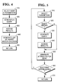
- FIG. 4 is a flowchart of another function for accessing the database.
- FIG. 5 is a flowchart of another function for accessing the database.
- FIG. 6 is a schematic representation of the presentation space.
- FIG. 7 is a schematic representation of perspective and orthographic transformations.
- FIG. 8 is a flowchart of the event handler.
- FIG. 9 is a relationship diagram of the event handler.
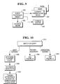
- FIG. 10 is a flowchart of how an event is processed.
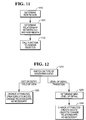
- FIG. 11 is a flowchart of how a region/boundary event is processed.
- FIG. 12 is a flowchart of how a rendering event is processed.
- FIG. 13 is a flowchart of the creation of the presentation space.
- FIG. 14 is a flowchart of expanding the presentation space.
- FIG. 15 is a flowchart of how each visualization element is expanded.
- FIG. 16A is a two-dimensional representation of the parent-child hierarchy.
- FIG. 16B is a two-dimensional representation of visualization elements.
- FIGS. 17A-17D are two dimensional representations of the view volume.
- FIG. 18 is a schematic diagram of a preferred hardware configuration.
- FIG. 19A is a node and relationship diagram.
- FIG. 19B is a hierarchial model of nodes via relationship A.
- FIG. 19C is a hierarchial model of nodes via relationship B.
- FIG. 19A shows an information system which includes nodes 1, 2, 3, 4, 5, 6, and 7 that are connected or related to each other via relationships A, B, and C.
- FIG. 19B shows the hierarchy model of the nodes in FIG. 19A via relationship A.
- FIG. 19C shows the hierarchy model of nodes in FIG. 19A via relationship B.
- FIG. 1 provides an overall structure for the system.
- the user provides parameters 110 through an input means.
- the parameters may include information such as the name of the information system to be explored, and the kinds of information of interest, and perhaps a starting point for exploration.
- the parameters are used by the system to select a storage means or database 120.
- the database is accessed 130 as further explained below and in FIG. 3.
- the system has a list of nodes that are used to build an initial presentation space 140, explained below and in FIG. 4.
- the system then builds a point of view into the presentation space called an avatar 150, explained below and in FIG. 5.
- the avatar is added to the visualization structure 160 and the user is then allowed to interact in the presentation space 170 through use of the input means and an image output means.
- the input means is a device such as a keyboard, mouse or a Spaceball that can provide signals based on actions from the user.
- a Spaceball is an input device available from Spatial Data Systems, Inc. that allows movement in each of the three dimensions, x, y and z. It also allows changes in orientation around each of the three axis: roll, pitch and yaw.
- An image output means is a device that can provide image as output.
- a display is an image output device that provides information in visible form, such as on a screen of a cathode ray tube or a flat panel display.
- the visible pattern presented by a display is an "image".
- FIG. 18 A computer 1801 is shown which contains a video display 1820, keyboard 1830, a mouse 1840, a Spaceball 1841, a central processing unit 1810 which can be an Intel 486, Pentium or Pentium Pro processor, etc., and may be used in conjunction with memory 1811, and a hard disk 1812.
- the computer 1801 may be connected to a network.
- the network may contain storage for a database 1850 and may also contain a database processing unit 1860. While this configuration is disclosed for the preferred embodiment, equivalent hardware systems or configurations may be substituted.
- the storage means is a repository of information for the information space and means for accessing such information.
- the repository is a standard database where a record in the database contains data that describes the node and its relationship to other records in the database.
- the information in the storage means may be static or it may change while the system is being used.
- the storage means may contain data corresponding to sensor values. Changes to the sensor values over time may be accomplished by changing the contents of a node in the storage means or it may be accomplished by the addition or deletion of nodes over time.
- a schematic representation of a node in the database is shown in FIG. 2.
- a node has a unique identifier 210.
- Information about the node may also include its parent identification 220, its children identification 230, and data that characterizes that node 240, 250, 260, and 270.
- findNodes() receives as input criteria in the form of parameters for selecting one or more nodes from the storage means.
- the criteria may specify nodes for which the parent identification is "0", null or empty (top level nodes).
- the storage means returns a set of nodes which are to be represented by graphical elements inside the presentation space.
- FIG. 3 is a flowchart illustrating how this function might be implemented. First the system gets parameters designating the range of nodes desired 310. The system then generates a query such as a call in SQL 320. The function gets the results 330 and generates a list of nodes 340 that are returned to the user 350.
- the interface to findNodes() is given below: NodeIDList* findNodes( selectionCriteriaList )
- Another function receives as input one of the nodes returned by findNodes() and parameters designating whether a parent or child is requested and the relation to be used.
- This function named followRelation() for illustrative purposes, returns the parent or child of the node received along some relation.
- the parameter designating the type of relation is used because there may be more than one hierarchical organization of the information space.
- the parent of a node could be two different nodes if the information space contains more than one organization.
- each record would contain the name of a person, the name of their biological father, and the name of their biological mother.
- One hierarchical view of the database is the “Father-Child” view of the database while a different hierarchical view of the same database is the “Mother-Child” view.
- the parameter may designate which biological parent is of interest.
- the second function returns either the parent node, children nodes or no nodes. If no nodes are returned, the node supplied to the second function has no nodes fitting the query requested (i.e. no parent or child exists).
- FIG. 4 is a flowchart of how followRelation() might be implemented.
- the function receives the node and parameters 410.
- the function then generates a query 420 and accesses the results 430. From the results, the function returns the parent or the children of the node 440 and this information is returned to the user 450.
- An example of the interface to followRelation() is given below: NodeIDList* followRelation( relationName, parentOrChildFlag, startNodeID)
- Another function supplies more information about a specific node. For illustrative purposes this function is named getNodeAttributes().
- the information that is returned is a data structure containing the attributes or values for the specified node.
- the attributes or values may also contain an aggregation of information about the children of the node.
- FIG. 5 is an example of how this function might be implemented.
- the parameters designating the node and the information requested from the node is supplied to the function 510.
- the function determines if a query is needed 520. The reason a query may not be needed is because the information desired has already been accessed by a previous call. If a query is needed a query is generated 530, the results are accessed 540 and a list of attributes for the node are generated 550. If no query is needed, a list of attributes is generated 550. From the list of generated attributes, the function determines whether any more information about the node is required 560. If more information is required the function loops again starting at selecting parameters. If no additional information is required, the function returns to the user with the information requested 570.
- getNodeAttributes() The interface for getNodeAttributes() is given below: NodeStructure* getNodeAttributes ( attributeSpecifiers, nodeID ) Note that it is possible to combine functions followRelation() and getNodeAttributes() into a single function that returns a list of node descriptions where the node description contains the parent/child information and the node attribute information.
- the processing means performs three tasks: (1) creation and update of the presentation space; (2) creation of the viewpoint or avatar; and (3) processing that allows the user to interact in the presentation space through use of the avatar or view point.
- the presentation space is conceptually a tree with visualization elements at each node of the tree graph.
- the initial presentation space is created by the processing means.
- this presentation space is a three-dimensional graphics space with a "scene-root node" that defines the origin of the space.
- the processing means begins by making a call to the storage means using findNodes() shown in FIG. 3. A list of nodes is returned by the first function.
- the processing means creates a visualization element for each of the nodes returned by the function 1320 and appends the visualization element to a visualization element list 1330.
- the visualization element is also added as a child of the scene-root 1340.
- the infoNode attribute of the visualization element is set to the node identification so that the node associated with the visualization element is easily accessed and identified 1350.
- information objects may be static or updated in real time, so too are visualization elements. For example, a visualization element that is data driven may not change while an animated visualization element is updated in real time.
- the processing means creates a hierarchical tree of these visualization elements as shown in FIG. 6 by making calls to the followRelation() shown in FIG. 4.
- each visualization element corresponds to a node in the storage means and the hierarchy of the visualization elements corresponds to the hierarchy of the information nodes.
- Function expandVisTree() receives as input a visualization element and the relation type of the information to be built.
- the node type is accessed from the visualization element and saved in NodeID 1410.
- the function followRelation() is called to get a list of the node's children 1420 which is kept in nodeIDList.
- a recursive loop is now started: (1) For each node in the node list nodeIDList, the processing means creates a visualization element for the node 1440; (2) A list is created of the top level visualization elements 1440, 1450; (3) The node identification field of the visualization element is set to the node identification for future access 1460; (4) The position and scale of the child visualization element is set relative to its parent's coordinate system to convey its relationship with its sibling visualization elements; (5) The child is "scaled" (i.e., the size of the child and all of its children recursively is reduced by some scale factor) so that it and all of its siblings will fit within the region defined by the parent visualization element 1470; and (6) The function calls itself to recursively expand the children of the current node 1480. In the preferred implementation, all of the immediate children of the visualization element are scaled by the same amount. This amount is termed "region scale".
- each of the root visualization elements will be expanded as shown by the following pseudo code segment:
- Each visualization element 610, 620, 630, 640, 650, 660 and 670 represents a region in the presentation space.
- the region of space defined by a visualization element contains the regions of space for all of the visualization element's children and recursively all of its children's children.
- Each one of the visualization elements in the presentation space has an affine spatial transformation.
- the affine spatial transformation is a mathematical function represented by a four by four transformation matrix, which is standard practice in the computer graphics field.
- the affine spatial transformation as used in computer graphics is described in more detail in text books such as "Fundamentals of Interactive Computer Graphics" by J.D. Foley and A. van Dam, Addison Wesley Publishing Company, Inc., 1982. They enable the use of "hierarchical coordinate systems" where a transformation on a parent coordinate system affects all of the child coordinate systems.
- An affine transformation is a linear transformation that preserves parallel geometry. Transformations such as scaling, translation (movement) and rotation are examples of affine transformations, while a perspective viewing transformation is not.
- the hierarchy of visualization elements in turn defines a hierarchy of coordinate systems. When a visualization element is scaled, rotated, or moved, the transformation will affect all of the children of the node and the children's children recursively.
- the processing means determines how the visualization element will be rendered onto the display means.
- the visualization elements may have attributes that control their appearance such as shape and color.
- the appearance of the visualization element may also be determined by its size as seen from some point of view. For example, if a visualization element is viewed from a large distance, its size on the display device may be small, while if the same object is viewed close up, it may appear quite large. If a visualization element's appearance is small, a simple representation is rendered. If a visualization element appears large, a more detailed representation may be rendered. In addition, it is not required that a visualization element have a visible appearance. If it does not have a shape associated with it, it will be invisible with no perceived boundaries, but its children may be visible within the invisible boundaries of their parent.
- each visualization element has a "bounding volume" defined that completely encloses the visualization element. This bounding volume is then intersected with the view volume to determine visibility. If the bounding volume does not intersect the view volume, then the view element is culled and the branch of the presentation space beneath the visualization element is pruned.
- a point-of-view is required for the presentation space to be rendered onto the display means.
- a point-of-view is defined by (1) a location in the presentation space, (2) an orientation that specifies the direction of view and the orientation of the viewpoint relative to the presentation space (i.e. , a line of sight vector and a vector that indicates which way "up” is), and (3) the view volume.
- the view volume is the region of the presentation space that will be rendered to the display means.
- the view volume is typically specified by a field-of-view attribute and two attributes known as the "near clipping plane" and the "far clipping plane.”
- the view volume is defined as that area within the field of view and between the near clipping plane and the far clipping plane.
- the view volume is a truncated pyramid or frustum. If an orthographic viewing projection is used the field-of-view angle is replaced by a field-of-view width and the resulting view volume is a rectangular parallelepiped.
- FIGs. 7A and 7B show a presentation space 700 containing a number of visualization elements 710, 720, 730 and 740.
- An avatar or viewpoint is located at position 701.
- a perspective viewing projection is shown in FIG. 7A.
- the angle at 702 is known as the field of view angle.
- the line 703 that bisects the field of view angle is known as the line of sight.
- the near clipping plane 770 and far clipping plane 780 (or lines in this figure) are perpendicular to the line of sight.
- the position of the near and far clipping planes are specified by the distance from the focal point along the line of sight. For example, in FIG.
- the view volume in a perspective transformation is that area bounded by the near clipping plane 770, the far clipping plane 780, and the field of view angle 702 defined by lines 790 and 775.
- the view volume in an orthographic transformation, is defined as that area bounded by the near clipping plane 770, the far clipping plane 780 and the lines 790 and 775. While more complex view volumes may be defined, the preferred implementation uses these forms of orthographic and perspective view volumes.
- the viewpoint or avatar has an additional attribute, "viewScale," that scales the view volume.
- viewScale attribute is represented as a positive real number with an initial value of 1.0.
- viewScale the distance from the viewpoint to the near clipping plane is scaled by a function: viewScale (i.e. viewScale * near ).
- viewScale the distance from the viewpoint to the near clipping plane is scaled by a function: viewScale (i.e. viewScale * near ).
- viewScale i.e. viewScale * near
- the ratio between the near and far clipping plane distances is kept constant by scaling both the near and far clipping plane distances by the same viewScale.
- the field-of-view width is scaled by viewScale.
- the near and far clipping planes for the orthographic viewing transformation are scaled in the same fashion as with the perspective viewing transformation.
- FIG. 16A shows a schematic representation of a parent node 1601 and its children 1602, 1603, 1604 and 1605.
- a visualization element is created for each node as represented in FIG. 16B.
- Associated with each visualization element is a region scale attribute.
- the region scale for visualization element 1600 is 1.0 because that is the complete presentation space.
- the view scale for the other visualization elements are as follows: Visualization Element Region Scale 1600 1.0 1601 0.2 1602 0.1 1603 0.2 1604 0.2 1605 0.33
- FIG. 17A shows the view point and view volume for when the view scale is 5.0 and the avatar or viewpoint is outside the region of visualization element 1601.
- the view scale is multiplied by the region scale associated with 1601.
- the resulting view scale value is 1.0.
- FIG. 17B As the avatar next enters the region of visualization element 1602, the view scale is further reduced by a factor of 0.1 so fewer objects are rendered but the objects that are rendered are shown in more detail.
- FIG. 17D as the avatar exits 1602, the avatar view scale is divided by 0.1 returning the view scale to 1.0.
- the view scale is changed to 0.33.
- An avatar is a viewpoint that also has an appearance associated with it.
- an avatar is defined that combines properties of the visualization element and viewpoint.
- the avatar is an animated figure or icon that represents the user in the presentation space. The user explores the information system by moving the avatar through the presentation space. As the avatar moves, different visualization elements will fall within the view volume. Only the visualization elements that intersect the view volume will be visible on the display means.
- the avatar is implemented as a data structure that extends the visualization element by adding a viewing transformation or a viewing projection.
- This projection can be an orthographic projection which is affine or a perspective viewing transformation that is not affine.
- the location and orientation of the avatar are properties that come from having the avatar being a visualization element. Since it is a visualization element, it can be attached to another visualization element within the presentation space. Therefore the movement of the avatar is relative to the coordinate system defined by the visualization element to which the avatar is attached. It is possible to have multiple avatars within one presentation space.
- the avatars may belong to a single user in which case the user can switch between avatars.
- the avatars may also belong to different users in the case where multiple people are exploring the same information space. Since the avatar is itself a visualization element, the avatars may be visible to the other avatars.
- the user interacts with the system through the input means, which may include but which is not limited to keyboard, mouse and a Spaceball. Any interaction from the user utilizing an input means generates an event with attribute(s) that characterize the input.
- An event is represented by a data structure that at a minimum indicates the event type.
- the data structure may be extended to contain additional event parameters. For example, a keystroke from the user generates an event with an attribute that indicated that a key was pressed and an attribute that indicates the specific key that was pressed. In general, events communicate a specific occurrence or specific situation.
- Event manager accepts events and acts upon them using the information contained within the event data structure. When an event manager receives an event, it may (1) change its internal state, (2) make a record of the event that occurred, (3) generates an action as a result, or (4) some combination of the above.
- FIG. 8 shows the flowchart for an event manager.
- An event manager first checks for system events 810. This is typically performed by polling or by queuing system calls.
- Events can be divided into three classes. There are user events which include mouse movement and key presses.
- the second class are region or boundary events where the avatar moves from one visualization element or region in the presentation space to another.
- the third type of events are visibility events that occur when the visualization elements are rendered either with more or less detail. For example, as an avatar moves toward an object the object becomes bigger and is rendered with more detail. Conversely, as the avatar moves away from an object, the object becomes smaller and the detail in the object is reduced. An event may be generated to signal that the level of detail is changing or needs to be changed.
- the event manager creates an event object for the event received 840.
- An event object contains attributes describing the kind of event and the characteristics of the event such as a mouse movement or key press.
- the event manager then processes the event 850 as explained below and in FIG. 9 and FIG. 10.
- the event manager calls the procedures to update the screen 830.
- the process of updating the screen uses standard rendering techniques from the computer graphics field.
- the structures within the presentation space, including the avatar, are traversed; at each node in the presentation graph the coordinate transformations are applied and drawing operations are performed based upon the attributes of the visualization elements (e.g., shape, color, etc.).
- FIG. 9 is a relationship diagram of events.
- An event manager 910 accesses the storage means 920, the current presentation space 930 and the avatar 940.
- a flowchart of the event manager is presented in FIG. 10.
- the event manager may be implemented as a switch statement on the class of event 1010. If the event is a user event, the event manager first determines the current state of the system 1020, determines the new state of the system 1030 and triggers the actions that correspond to the state transition 1040. These actions can include the creation and deletion of objects, the changing of object attributes, the changing of relations between objects, and the changing of local state variables. The effect of these actions may be to change some aspect of the presentation space or it may cause some change in the information system being presented.
- the system first determines the new region 1110, determines the relationship between the new and old regions 1120. This includes the depth of the lowest common visualization element.
- the viewScale attribute of the avatar must be adjusted to correspond to the accumulated scale (from the root to the current region) of the region being entered. This scaling enables the viewing of the multi-resolution presentation. This is accomplished by function 1130 which takes as arguments (1) the new region, (2) the relationship between the old and new regions, and (3) the lowest common visualization element.
- function 1130 may cause additional actions to be performed, such as expanding the part of the visualization structure within the new region, or deleting visualization elements within the old region.
- the system may contain a case statement on the type of rendering event 1210. If the event is one which moves the avatar so that objects enter and exit the field of view, the system calls functions to change the attributes of the objects from visible to non visible or vice versa. The system may also add or delete visualization elements 1220 depending if they are in the field of view and it may also change relationships of visualization elements as necessary 1220.
- the other type of event for rendering an object is changing the level of detail of a visible object. For this type of event, the system determines the new level of detail 1230 and then changes the attributes of the object, it creates or deletes objects and changes relationships between objects as necessary.
- One use of this aspect is that when initially expanding the visualization element tree, a fixed depth is specified so that only the top levels are created. As the user moves the avatar through the presentation space and the level of detail changes, the system may respond to the events by expanding the level of detail for specific branches of the presentation space or by discarding low level detailed visualization elements as they fall outside the limits of visibility.
Landscapes
- Engineering & Computer Science (AREA)
- Databases & Information Systems (AREA)
- Theoretical Computer Science (AREA)
- Data Mining & Analysis (AREA)
- Physics & Mathematics (AREA)
- General Engineering & Computer Science (AREA)
- General Physics & Mathematics (AREA)
- Processing Or Creating Images (AREA)
- Digital Computer Display Output (AREA)
- Image Generation (AREA)
- User Interface Of Digital Computer (AREA)
- Information Retrieval, Db Structures And Fs Structures Therefor (AREA)
Applications Claiming Priority (2)
| Application Number | Priority Date | Filing Date | Title |
|---|---|---|---|
| US695470 | 1996-08-12 | ||
| US08/695,470 US5923330A (en) | 1996-08-12 | 1996-08-12 | System and method for navigation and interaction in structured information spaces |
Publications (3)
| Publication Number | Publication Date |
|---|---|
| EP0827090A2 true EP0827090A2 (de) | 1998-03-04 |
| EP0827090A3 EP0827090A3 (de) | 1999-08-18 |
| EP0827090B1 EP0827090B1 (de) | 2004-10-06 |
Family
ID=24793113
Family Applications (1)
| Application Number | Title | Priority Date | Filing Date |
|---|---|---|---|
| EP97305463A Expired - Lifetime EP0827090B1 (de) | 1996-08-12 | 1997-07-22 | Navigation und Interaktion in strukturierten Informationsräumen |
Country Status (4)
| Country | Link |
|---|---|
| US (1) | US5923330A (de) |
| EP (1) | EP0827090B1 (de) |
| JP (1) | JPH1091649A (de) |
| DE (1) | DE69731045T2 (de) |
Cited By (2)
| Publication number | Priority date | Publication date | Assignee | Title |
|---|---|---|---|---|
| GB2324896A (en) * | 1997-03-13 | 1998-11-04 | Mitel Corp | Web page generator for organizational directory |
| GB2331604A (en) * | 1997-10-07 | 1999-05-26 | Cabletron Systems Inc | Dynamic network navigation tree |
Families Citing this family (93)
| Publication number | Priority date | Publication date | Assignee | Title |
|---|---|---|---|---|
| US7859551B2 (en) * | 1993-10-15 | 2010-12-28 | Bulman Richard L | Object customization and presentation system |
| JPH1040197A (ja) * | 1996-07-19 | 1998-02-13 | Fujitsu Ltd | 通信管理装置 |
| US6396509B1 (en) * | 1998-02-21 | 2002-05-28 | Koninklijke Philips Electronics N.V. | Attention-based interaction in a virtual environment |
| US6348927B1 (en) * | 1998-02-27 | 2002-02-19 | Oracle Cor | Composing a description of a virtual 3D world from values stored in a database and generated by decomposing another description of a virtual 3D world |
| US6088698A (en) * | 1998-02-27 | 2000-07-11 | Oracle Corporation | Method and apparatus for incrementally generating a virtual three-dimensional world |
| US6151595A (en) * | 1998-04-17 | 2000-11-21 | Xerox Corporation | Methods for interactive visualization of spreading activation using time tubes and disk trees |
| KR100298789B1 (ko) * | 1998-04-29 | 2001-09-06 | 윤종용 | 그래픽 처리에 있어서 클리핑 처리방법 |
| JP4240343B2 (ja) * | 1998-12-19 | 2009-03-18 | 株式会社セガ | 画像生成装置および画像生成方法 |
| US7839399B2 (en) | 1999-07-29 | 2010-11-23 | Benman William J | System and method for volumetric display of video images extracted from arbitrary background environments |
| US6983236B1 (en) * | 1999-10-12 | 2006-01-03 | Aprisa, Inc. | Method for system-constraint-based selection for design components |
| US6922682B1 (en) | 1999-10-12 | 2005-07-26 | Aprisa, Inc. | Method and system for engineering discovery |
| US7693697B2 (en) * | 1999-12-07 | 2010-04-06 | University Of Utah Research Foundation | Anesthesia drug monitor |
| US7654966B2 (en) * | 1999-12-07 | 2010-02-02 | University Of Utah Research Foundation | Method and apparatus for monitoring dynamic cardiovascular function using n-dimensional representatives of critical functions |
| AU1949501A (en) * | 1999-12-07 | 2001-06-18 | University Of Utah Research Foundation | Method and apparatus for monitoring dynamic systems using n-dimensional representations of critical functions |
| KR100407033B1 (ko) * | 1999-12-22 | 2003-11-28 | 김정태 | 정보 모델링방법에 의해 데이터베이스를 구축하고, 구축된 데이터베이스를 이용하여 정보를 검색하는 방법, |
| US6766343B1 (en) * | 2000-02-04 | 2004-07-20 | Harris Corporation | Method and apparatus for coordinate system conversions |
| US6928087B2 (en) * | 2000-02-10 | 2005-08-09 | Telefonaktiebolaget Lm Ericsson (Publ) | Method and apparatus for automatic cross-media selection and scaling |
| US6760720B1 (en) | 2000-02-25 | 2004-07-06 | Pedestrian Concepts, Inc. | Search-on-the-fly/sort-on-the-fly search engine for searching databases |
| US6344837B1 (en) | 2000-06-16 | 2002-02-05 | Andrew H. Gelsey | Three-dimensional image display with picture elements formed from directionally modulated pixels |
| US20020015003A1 (en) * | 2000-08-07 | 2002-02-07 | Masami Kato | Virtual space system structured by plural user terminals and server device |
| US6950791B1 (en) * | 2000-09-13 | 2005-09-27 | Antartica Systems, Inc. | Method for describing objects in a virtual space |
| US7788323B2 (en) * | 2000-09-21 | 2010-08-31 | International Business Machines Corporation | Method and apparatus for sharing information in a virtual environment |
| US6910186B2 (en) | 2000-12-08 | 2005-06-21 | Kyunam Kim | Graphic chatting with organizational avatars |
| US20020129342A1 (en) * | 2001-03-07 | 2002-09-12 | David Kil | Data mining apparatus and method with user interface based ground-truth tool and user algorithms |
| US6909429B2 (en) * | 2001-05-18 | 2005-06-21 | A.G. Imaginations Ltd. | System and method for displaying content in a three-dimensional virtual environment |
| US20030164827A1 (en) * | 2001-05-18 | 2003-09-04 | Asaf Gottesman | System and method for displaying search results in a three-dimensional virtual environment |
| JP3747404B2 (ja) * | 2001-06-19 | 2006-02-22 | インターナショナル・ビジネス・マシーンズ・コーポレーション | グラフィックス・イメージ作成装置、及びその方法並びにプログラム |
| US7334196B2 (en) * | 2001-06-25 | 2008-02-19 | Siemens Medical Solutions Health Services Corporation | User interface display navigation and item selection system |
| US6602075B2 (en) * | 2001-11-20 | 2003-08-05 | Discovertheoutdoors.Com, Inc. | Method of teaching through exposure to relevant perspective |
| US6602076B2 (en) * | 2001-11-20 | 2003-08-05 | Discovertheoutdoors.Com, Inc. | Method of teaching through exposure to relevant perspective |
| KR100446635B1 (ko) * | 2001-11-27 | 2004-09-04 | 삼성전자주식회사 | 깊이 이미지 기반 3차원 객체 표현 장치 및 방법 |
| US6791549B2 (en) * | 2001-12-21 | 2004-09-14 | Vrcontext S.A. | Systems and methods for simulating frames of complex virtual environments |
| US8612196B2 (en) * | 2002-04-11 | 2013-12-17 | Linden Research, Inc. | System and method for distributed simulation in which different simulation servers simulate different regions of a simulation space |
| US7305611B2 (en) * | 2002-08-22 | 2007-12-04 | Platform Digital Llc | Authoring tool for remote experience lessons |
| US7862428B2 (en) | 2003-07-02 | 2011-01-04 | Ganz | Interactive action figures for gaming systems |
| US7617177B2 (en) * | 2003-08-06 | 2009-11-10 | Sap Ag | Methods and systems for providing benchmark information under controlled access |
| US7725947B2 (en) * | 2003-08-06 | 2010-05-25 | Sap Ag | Methods and systems for providing benchmark information under controlled access |
| CA2697021C (en) * | 2003-12-31 | 2014-04-08 | Howard Ganz | System and method for toy adoption and marketing |
| US7534157B2 (en) * | 2003-12-31 | 2009-05-19 | Ganz | System and method for toy adoption and marketing |
| US20050195186A1 (en) * | 2004-03-02 | 2005-09-08 | Ati Technologies Inc. | Method and apparatus for object based visibility culling |
| US20090019064A1 (en) * | 2005-02-14 | 2009-01-15 | Justsystems Corporation | Document processing device and document processing method |
| KR100707206B1 (ko) * | 2005-04-11 | 2007-04-13 | 삼성전자주식회사 | 3차원 객체의 깊이영상 기반 표현 방법 및 이를 이용한모델링 및 렌더링 방법 및 장치 |
| US7779004B1 (en) | 2006-02-22 | 2010-08-17 | Qurio Holdings, Inc. | Methods, systems, and products for characterizing target systems |
| US9329743B2 (en) * | 2006-10-04 | 2016-05-03 | Brian Mark Shuster | Computer simulation method with user-defined transportation and layout |
| NZ564006A (en) * | 2006-12-06 | 2009-03-31 | 2121200 Ontario Inc | System and method for product marketing using feature codes |
| US7983955B2 (en) * | 2006-12-06 | 2011-07-19 | Ganz | System and method for tiered website access |
| KR100864564B1 (ko) | 2007-01-11 | 2008-10-20 | 한국문화콘텐츠진흥원 | 시나리오 기반의 문화 유산 저작 시스템 |
| US7840903B1 (en) | 2007-02-26 | 2010-11-23 | Qurio Holdings, Inc. | Group content representations |
| US7849420B1 (en) | 2007-02-26 | 2010-12-07 | Qurio Holdings, Inc. | Interactive content representations enabling content sharing |
| US9098167B1 (en) * | 2007-02-26 | 2015-08-04 | Qurio Holdings, Inc. | Layered visualization of content representations |
| US20080214304A1 (en) * | 2007-03-02 | 2008-09-04 | Electronic Arts, Inc. | User interface for selecting items in a video game |
| US7970663B2 (en) * | 2007-05-02 | 2011-06-28 | Ganz | Method of calculating an estimated market value of a character |
| US8260266B1 (en) | 2007-06-26 | 2012-09-04 | Qurio Holdings, Inc. | Method and system for third-party discovery of proximity-based services |
| US8350844B2 (en) * | 2007-08-20 | 2013-01-08 | International Business Machines Corporation | Monitoring user attention in a computer-simulated environment |
| US9111285B2 (en) * | 2007-08-27 | 2015-08-18 | Qurio Holdings, Inc. | System and method for representing content, user presence and interaction within virtual world advertising environments |
| US8250169B2 (en) * | 2007-09-24 | 2012-08-21 | Sap Ag | Business context data companion tool |
| US8127237B2 (en) | 2007-09-24 | 2012-02-28 | Sap Ag | Active business client |
| JP4985970B2 (ja) * | 2007-10-24 | 2012-07-25 | インターナショナル・ビジネス・マシーンズ・コーポレーション | オブジェクトの表示を制御する技術 |
| US8261307B1 (en) | 2007-10-25 | 2012-09-04 | Qurio Holdings, Inc. | Wireless multimedia content brokerage service for real time selective content provisioning |
| US20090132357A1 (en) * | 2007-11-19 | 2009-05-21 | Ganz, An Ontario Partnership Consisting Of S.H. Ganz Holdings Inc. And 816877 Ontario Limited | Transfer of rewards from a central website to other websites |
| US8612302B2 (en) | 2007-11-19 | 2013-12-17 | Ganz | Credit swap in a virtual world |
| US8626819B2 (en) | 2007-11-19 | 2014-01-07 | Ganz | Transfer of items between social networking websites |
| US8088002B2 (en) | 2007-11-19 | 2012-01-03 | Ganz | Transfer of rewards between websites |
| JP4881903B2 (ja) * | 2008-03-18 | 2012-02-22 | ヤフー株式会社 | 自然言語対話エージェントのためのスクリプト作成支援方法及びプログラム |
| KR100888156B1 (ko) * | 2008-05-15 | 2009-03-10 | 팅크웨어(주) | 안내 심볼 출력 시스템 및 방법 |
| US20100185651A1 (en) * | 2009-01-16 | 2010-07-22 | Google Inc. | Retrieving and displaying information from an unstructured electronic document collection |
| US8615707B2 (en) * | 2009-01-16 | 2013-12-24 | Google Inc. | Adding new attributes to a structured presentation |
| US8452791B2 (en) * | 2009-01-16 | 2013-05-28 | Google Inc. | Adding new instances to a structured presentation |
| US8977645B2 (en) * | 2009-01-16 | 2015-03-10 | Google Inc. | Accessing a search interface in a structured presentation |
| US8412749B2 (en) * | 2009-01-16 | 2013-04-02 | Google Inc. | Populating a structured presentation with new values |
| US8782530B2 (en) * | 2009-03-25 | 2014-07-15 | Sap Ag | Method and system for providing a user interface in a computer |
| US8712953B2 (en) * | 2009-03-25 | 2014-04-29 | Sap Ag | Data consumption framework for semantic objects |
| US8161398B2 (en) * | 2009-05-08 | 2012-04-17 | International Business Machines Corporation | Assistive group setting management in a virtual world |
| US20100306223A1 (en) * | 2009-06-01 | 2010-12-02 | Google Inc. | Rankings in Search Results with User Corrections |
| US20110106819A1 (en) * | 2009-10-29 | 2011-05-05 | Google Inc. | Identifying a group of related instances |
| US20110165939A1 (en) * | 2010-01-05 | 2011-07-07 | Ganz | Method and system for providing a 3d activity in a virtual presentation |
| US8836719B2 (en) | 2010-04-23 | 2014-09-16 | Ganz | Crafting system in a virtual environment |
| US8725476B1 (en) * | 2010-05-04 | 2014-05-13 | Lucasfilm Entertainment Company Ltd. | Applying details in a simulation |
| KR20120050083A (ko) * | 2010-11-10 | 2012-05-18 | 삼성전자주식회사 | 디스플레이장치, 리모트 컨트롤러 및 이들의 제어방법 |
| US8970592B1 (en) | 2011-04-19 | 2015-03-03 | Lucasfilm Entertainment Company LLC | Simulating an arbitrary number of particles |
| US9454554B1 (en) * | 2011-05-12 | 2016-09-27 | Bentley Systems, Incorporated | View dependent query of multi-resolution clustered 3D dataset |
| US8721456B2 (en) | 2012-02-17 | 2014-05-13 | Ganz | Incentivizing playing between websites |
| US9123162B2 (en) | 2012-06-11 | 2015-09-01 | Disney Enterprises, Inc. | Integration cone tracing |
| US8957896B2 (en) * | 2012-06-11 | 2015-02-17 | Disney Enterprises, Inc. | Streaming hierarchy traversal renderer |
| US9053582B2 (en) | 2012-06-11 | 2015-06-09 | Disney Enterprises, Inc. | Streaming light propagation |
| US20140039806A1 (en) * | 2012-08-02 | 2014-02-06 | Siemens Corporation | Estimating remaining useful life from prognostic features discovered using genetic programming |
| US9123154B2 (en) | 2012-10-09 | 2015-09-01 | Disney Enterprises, Inc. | Distributed element rendering |
| US9508315B2 (en) | 2013-03-08 | 2016-11-29 | Disney Enterprises, Inc. | Ordering rays in rendered graphics for coherent shading |
| US9514560B2 (en) | 2013-03-15 | 2016-12-06 | Dreamworks Animation Llc | Arbitrary hierarchical tagging of computer-generated animation assets |
| US9933917B2 (en) * | 2014-08-13 | 2018-04-03 | Bank Of America Corporation | System and method for generating and navigating a bonsai tree hierarchical data structure |
| US10572108B2 (en) * | 2017-07-20 | 2020-02-25 | Vmware, Inc. | Hierarchical inventory tree operation |
| US11389735B2 (en) | 2019-10-23 | 2022-07-19 | Ganz | Virtual pet system |
| US11358059B2 (en) | 2020-05-27 | 2022-06-14 | Ganz | Live toy system |
Family Cites Families (16)
| Publication number | Priority date | Publication date | Assignee | Title |
|---|---|---|---|---|
| US4613946A (en) * | 1984-06-07 | 1986-09-23 | Forman Ernest H | Method and apparatus for generating hierarchical displays |
| US5262761A (en) * | 1987-09-08 | 1993-11-16 | Intelligent Micro Systems, Inc. | Displaying hierarchical tree-like designs in windows |
| US4821211A (en) * | 1987-11-19 | 1989-04-11 | International Business Machines Corp. | Method of navigating among program menus using a graphical menu tree |
| JPH01250129A (ja) * | 1988-03-02 | 1989-10-05 | Hitachi Ltd | 表示制御方法および表示装置 |
| US5021976A (en) * | 1988-11-14 | 1991-06-04 | Microelectronics And Computer Technology Corporation | Method and system for generating dynamic, interactive visual representations of information structures within a computer |
| US5119477A (en) * | 1989-10-23 | 1992-06-02 | International Business Machines Corporation | Memory manager for hierarchical graphic structures |
| US5295243A (en) * | 1989-12-29 | 1994-03-15 | Xerox Corporation | Display of hierarchical three-dimensional structures with rotating substructures |
| US5287514A (en) * | 1990-01-08 | 1994-02-15 | Microsoft Corporation | Method and system for customizing a user interface in a computer system |
| EP0548240A1 (de) * | 1990-09-10 | 1993-06-30 | Lotus Development Corporation | Gerät und verfahren für einen wiederformatierbaren tabulator |
| US5524187A (en) * | 1991-03-25 | 1996-06-04 | The Trustees Of Columbia University | Worlds-within-worlds nested display and interaction system and method |
| US5528735A (en) * | 1993-03-23 | 1996-06-18 | Silicon Graphics Inc. | Method and apparatus for displaying data within a three-dimensional information landscape |
| US5555354A (en) * | 1993-03-23 | 1996-09-10 | Silicon Graphics Inc. | Method and apparatus for navigation within three-dimensional information landscape |
| JP3433803B2 (ja) * | 1993-07-07 | 2003-08-04 | ヨーロピアン コンピューター − インダストリー リサーチ センター ゲーエムベーハー | データベースの構造 |
| US5689628A (en) * | 1994-04-14 | 1997-11-18 | Xerox Corporation | Coupling a display object to a viewpoint in a navigable workspace |
| US5689669A (en) * | 1994-04-29 | 1997-11-18 | General Magic | Graphical user interface for navigating between levels displaying hallway and room metaphors |
| US5682469A (en) * | 1994-07-08 | 1997-10-28 | Microsoft Corporation | Software platform having a real world interface with animated characters |
-
1996
- 1996-08-12 US US08/695,470 patent/US5923330A/en not_active Expired - Lifetime
-
1997
- 1997-07-22 DE DE69731045T patent/DE69731045T2/de not_active Expired - Lifetime
- 1997-07-22 EP EP97305463A patent/EP0827090B1/de not_active Expired - Lifetime
- 1997-08-06 JP JP9211456A patent/JPH1091649A/ja active Pending
Cited By (4)
| Publication number | Priority date | Publication date | Assignee | Title |
|---|---|---|---|---|
| GB2324896A (en) * | 1997-03-13 | 1998-11-04 | Mitel Corp | Web page generator for organizational directory |
| US5940834A (en) * | 1997-03-13 | 1999-08-17 | Mitel Corporation | Automatic web page generator |
| GB2324896B (en) * | 1997-03-13 | 2000-02-23 | Mitel Corp | Automatic web page generator |
| GB2331604A (en) * | 1997-10-07 | 1999-05-26 | Cabletron Systems Inc | Dynamic network navigation tree |
Also Published As
| Publication number | Publication date |
|---|---|
| EP0827090A3 (de) | 1999-08-18 |
| DE69731045D1 (de) | 2004-11-11 |
| EP0827090B1 (de) | 2004-10-06 |
| US5923330A (en) | 1999-07-13 |
| JPH1091649A (ja) | 1998-04-10 |
| DE69731045T2 (de) | 2005-11-24 |
Similar Documents
| Publication | Publication Date | Title |
|---|---|---|
| EP0827090B1 (de) | Navigation und Interaktion in strukturierten Informationsräumen | |
| US6204850B1 (en) | Scaleable camera model for the navigation and display of information structures using nested, bounded 3D coordinate spaces | |
| US6938218B1 (en) | Method and apparatus for three dimensional internet and computer file interface | |
| US5546529A (en) | Method and apparatus for visualization of database search results | |
| US5339390A (en) | Operating a processor to display stretched continuation of a workspace | |
| US6025843A (en) | Clustering user interface | |
| EP0535986B1 (de) | Verfahren zur Bedienung eines Prozessors | |
| US5790121A (en) | Clustering user interface | |
| Ayers et al. | Using graphic history in browsing the World Wide Web | |
| US5555354A (en) | Method and apparatus for navigation within three-dimensional information landscape | |
| US7012602B2 (en) | Virtual three-dimensional display for product development | |
| EP0982669A2 (de) | Auf Eigenschaften basierende Kontextportale | |
| US20060119618A1 (en) | Graphical interface for manipulation of 3D models | |
| US20030011601A1 (en) | Graphics image creation apparatus, and method and program therefor | |
| EP0982670A2 (de) | Dynamische Objektvisualisierung und Kodegeneration | |
| US20030164827A1 (en) | System and method for displaying search results in a three-dimensional virtual environment | |
| EP1835466A2 (de) | Verfahren und Vorrichtung zur Verarbeitung geometrischer Daten und Teilekatalogsystem | |
| US20020174121A1 (en) | Information management system and method | |
| Kuhn | Are displays maps or views? | |
| JP5372590B2 (ja) | 情報処理装置、情報処理方法、およびプログラム | |
| Neves et al. | Cognitive spaces and metaphors: A solution for interacting with spatial data | |
| US20030193528A1 (en) | Hierarchical data structure which enables interactive visualization of a geographical space | |
| Voisard | Towards a toolbox for geographic user interfaces | |
| Eyl | The harmony information landscape: interactive, three-dimensional navigation through an information space | |
| Gobbetti et al. | i3D: An interactive system for exploring annotated 3D environments |
Legal Events
| Date | Code | Title | Description |
|---|---|---|---|
| PUAI | Public reference made under article 153(3) epc to a published international application that has entered the european phase |
Free format text: ORIGINAL CODE: 0009012 |
|
| AK | Designated contracting states |
Kind code of ref document: A2 Designated state(s): DE FR GB |
|
| PUAL | Search report despatched |
Free format text: ORIGINAL CODE: 0009013 |
|
| AK | Designated contracting states |
Kind code of ref document: A3 Designated state(s): AT BE CH DE DK ES FI FR GB GR IE IT LI LU MC NL PT SE |
|
| 17P | Request for examination filed |
Effective date: 20000218 |
|
| AKX | Designation fees paid |
Free format text: DE FR GB |
|
| GRAP | Despatch of communication of intention to grant a patent |
Free format text: ORIGINAL CODE: EPIDOSNIGR1 |
|
| GRAS | Grant fee paid |
Free format text: ORIGINAL CODE: EPIDOSNIGR3 |
|
| GRAA | (expected) grant |
Free format text: ORIGINAL CODE: 0009210 |
|
| AK | Designated contracting states |
Kind code of ref document: B1 Designated state(s): DE FR GB |
|
| REG | Reference to a national code |
Ref country code: GB Ref legal event code: FG4D |
|
| REF | Corresponds to: |
Ref document number: 69731045 Country of ref document: DE Date of ref document: 20041111 Kind code of ref document: P |
|
| PLBE | No opposition filed within time limit |
Free format text: ORIGINAL CODE: 0009261 |
|
| STAA | Information on the status of an ep patent application or granted ep patent |
Free format text: STATUS: NO OPPOSITION FILED WITHIN TIME LIMIT |
|
| ET | Fr: translation filed | ||
| 26N | No opposition filed |
Effective date: 20050707 |
|
| REG | Reference to a national code |
Ref country code: GB Ref legal event code: 746 Effective date: 20080919 |
|
| REG | Reference to a national code |
Ref country code: FR Ref legal event code: PLFP Year of fee payment: 20 |
|
| PGFP | Annual fee paid to national office [announced via postgrant information from national office to epo] |
Ref country code: DE Payment date: 20160726 Year of fee payment: 20 Ref country code: GB Payment date: 20160727 Year of fee payment: 20 |
|
| PGFP | Annual fee paid to national office [announced via postgrant information from national office to epo] |
Ref country code: FR Payment date: 20160726 Year of fee payment: 20 |
|
| REG | Reference to a national code |
Ref country code: DE Ref legal event code: R071 Ref document number: 69731045 Country of ref document: DE |
|
| REG | Reference to a national code |
Ref country code: GB Ref legal event code: PE20 Expiry date: 20170721 |
|
| PG25 | Lapsed in a contracting state [announced via postgrant information from national office to epo] |
Ref country code: GB Free format text: LAPSE BECAUSE OF EXPIRATION OF PROTECTION Effective date: 20170721 |