EP0827847A2 - Zentrallager für eine Hinterachse eines Kraftfahrzeuges - Google Patents
Zentrallager für eine Hinterachse eines Kraftfahrzeuges Download PDFInfo
- Publication number
- EP0827847A2 EP0827847A2 EP97110181A EP97110181A EP0827847A2 EP 0827847 A2 EP0827847 A2 EP 0827847A2 EP 97110181 A EP97110181 A EP 97110181A EP 97110181 A EP97110181 A EP 97110181A EP 0827847 A2 EP0827847 A2 EP 0827847A2
- Authority
- EP
- European Patent Office
- Prior art keywords
- bearing
- bracket
- elastic
- support surfaces
- rear axle
- Prior art date
- Legal status (The legal status is an assumption and is not a legal conclusion. Google has not performed a legal analysis and makes no representation as to the accuracy of the status listed.)
- Granted
Links
Images
Classifications
-
- B—PERFORMING OPERATIONS; TRANSPORTING
- B60—VEHICLES IN GENERAL
- B60G—VEHICLE SUSPENSION ARRANGEMENTS
- B60G7/00—Pivoted suspension arms; Accessories thereof
- B60G7/02—Attaching arms to sprung part of vehicle
-
- B—PERFORMING OPERATIONS; TRANSPORTING
- B60—VEHICLES IN GENERAL
- B60G—VEHICLE SUSPENSION ARRANGEMENTS
- B60G9/00—Resilient suspensions of a rigid axle or axle housing for two or more wheels
- B60G9/02—Resilient suspensions of a rigid axle or axle housing for two or more wheels the axle or housing being pivotally mounted on the vehicle, e.g. the pivotal axis being parallel to the longitudinal axis of the vehicle
-
- B—PERFORMING OPERATIONS; TRANSPORTING
- B60—VEHICLES IN GENERAL
- B60G—VEHICLE SUSPENSION ARRANGEMENTS
- B60G2200/00—Indexing codes relating to suspension types
- B60G2200/30—Rigid axle suspensions
- B60G2200/32—Rigid axle suspensions pivoted
- B60G2200/324—Rigid axle suspensions pivoted with a single pivot point and a triangular "T" or "U"-shaped axle, e.g. DeDion arrangement
-
- B—PERFORMING OPERATIONS; TRANSPORTING
- B60—VEHICLES IN GENERAL
- B60G—VEHICLE SUSPENSION ARRANGEMENTS
- B60G2204/00—Indexing codes related to suspensions per se or to auxiliary parts
- B60G2204/10—Mounting of suspension elements
- B60G2204/14—Mounting of suspension arms
- B60G2204/143—Mounting of suspension arms on the vehicle body or chassis
-
- B—PERFORMING OPERATIONS; TRANSPORTING
- B60—VEHICLES IN GENERAL
- B60G—VEHICLE SUSPENSION ARRANGEMENTS
- B60G2204/00—Indexing codes related to suspensions per se or to auxiliary parts
- B60G2204/40—Auxiliary suspension parts; Adjustment of suspensions
- B60G2204/41—Elastic mounts, e.g. bushings
- B60G2204/4104—Bushings having modified rigidity in particular directions
-
- B—PERFORMING OPERATIONS; TRANSPORTING
- B60—VEHICLES IN GENERAL
- B60G—VEHICLE SUSPENSION ARRANGEMENTS
- B60G2204/00—Indexing codes related to suspensions per se or to auxiliary parts
- B60G2204/40—Auxiliary suspension parts; Adjustment of suspensions
- B60G2204/418—Bearings, e.g. ball or roller bearings
-
- B—PERFORMING OPERATIONS; TRANSPORTING
- B60—VEHICLES IN GENERAL
- B60G—VEHICLE SUSPENSION ARRANGEMENTS
- B60G2204/00—Indexing codes related to suspensions per se or to auxiliary parts
- B60G2204/40—Auxiliary suspension parts; Adjustment of suspensions
- B60G2204/45—Stops limiting travel
- B60G2204/4502—Stops limiting travel using resilient buffer
Definitions
- the invention relates to a central bearing for a rear axle Motor vehicle according to the preamble of claim 1.
- An elastic bearing for a wheel suspension is known from DE 26 25 374 A1, which is arranged in the center and comprises elastic ring elements which have a twist of two interconnected axle ends on each side of the wheel.
- the object of the invention is to provide a rear axle for a motor vehicle to create a central warehouse that requires little construction and Defined identifiers in the longitudinal, transverse and vertical direction guaranteed.
- the two separated bearing elements are clamped together using a overlapping ring bracket, which in turn is held in a sleeve, which is part of a Bearing bracket is that with the web of a U-shaped bracket on the rear axle is connected.
- Support surfaces are formed, which are opposite support surfaces of the ring bracket.
- the bearing elements can be moved gimbally between these support surfaces.
- the tubular part of the bearing axle bracket protrudes by one dimension, which corresponds to the degree of compression of the elastic elements in the assembled condition corresponds.
- Radially extending cushions can serve as an elastic stop two elastic bearing elements are formed in the colliding area and the ring bracket are prepared.
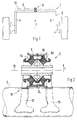
- a rear axle 1 consists essentially of a U-shaped bracket 2 with a web 3 extending in the vehicle transverse direction and adjoining in FIG Legs 4 and 5 extending in the longitudinal direction of the vehicle. At the free ends of these Legs 4, 5, the wheels are held on wheel carrier recordings.
- the rear axle 1 is mounted on the vehicle body via a central bearing 6 and can thus move the wheels around swivel a transverse axis and inclined axes.
- the central bearing 6 is formed from two separate bearing elements 7, 8, which in one Ring bracket 9 are kept attached together.
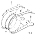
- the ring bracket 9 is in turn in one Sleeve 10 of a bearing bracket 11 is arranged. This is via arms 12, 13 with the Web 3 of the rear axle 1 connected.
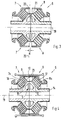
- the bearing elements 7, 8 comprise elastic rings 7a, 8a, which on a Bearing axle bracket 14 between molded support surfaces 15, 16 and support surfaces 17, 18 of the ring bracket are held. These support surfaces 15, 16 are among the others Support surfaces 17, 18 are arranged approximately parallel and are inclined at an angle to the bearing axis 19. The two support surfaces 15, 16 of the bearing axis carrier 14 complement each other to form an approximately rectangular, protruding support element S.
- a gimbal movement of the axis can be carried out via the central bearing 6 with torsional forces. Furthermore, defined forces in vertical, transverse and longitudinal directions. Via elastic stops 24, can limit the movement of the central bearing 1 in longitudinal and Vertical direction.
Landscapes
- Engineering & Computer Science (AREA)
- Mechanical Engineering (AREA)
- Support Of The Bearing (AREA)
- Vehicle Body Suspensions (AREA)
- Warehouses Or Storage Devices (AREA)
Abstract
Description
- Fig. 1
- eine schematische Darstellung einer Hinterachse für ein Kraftfahrzeug mit Zentrallager,
- Fig. 2
- einen Horizontalschnitt durch das Zentrallager mit Anbindung an die Hinterachse,
- Fig. 3
- einen Schnitt durch das Zentrallager vor einem zusammengebauten Zustand,
- Fig. 4
- einen Schnitt durch das Zentrallager im zusammengebauten Zustand und
- Fig. 5
- eine schaubildliche Darstellung einer das Zentrallager aufnehmenden Lagerkonsole.
Claims (5)
- Zentrallager für eine Hinterachse eines Kraftfahrzeuges, die aus einem U-förmigen Bügel besteht, mit dessen freie Schenkelenden über Aufnahmen Räder verbunden sind, dadurch gekennzeichnet, daß das Zentrallager (1) zwei zusammengesetzte elastische Lagerelemente (7, 8) umfaßt, die einen Ringbügel (9) zusammenghalten sind und die eine parallel zum Steg (3) des Hinterachs-Bügels (2) angeordnete Lagerachse (19) in einem Lagerachsenträger (14) aufweisen, wobei die Lagerelemente (7, 8) in einer Hülse (10) gehalten und mit einer am Bügel (2) befestigbaren Lagerkonsole (11) verbunden sind.
- Zentrallager nach Anspruch 1, dadurch gekennzeichnet, daß die Lagerelemente (7, 8) aus elastischen Ringen (7a, 8a) bestehen, welche zwischen etwa parallel und schräg zur Lagerachse (19) angeordneten Stützflächen (15, 16 und 17, 18) des Lagerachsenträgers (14) und des Ringbügels (9) gehalten sind.
- Zentrallager nach den Ansprüchen 1 oder 2, dadurch gekennzeichnet, daß der Lagerachsenträger (14) jeweils aus einem Rohrteil mit einer angeformten schrägen Stützfläche (15, 16) besteht und die Stützflächen beider Lagerelemente (7, 8) radial vorragend ein etwa rechtwinkelig ausgebildetes Stützelement (5) bilden.
- Zentrallager nach den Ansprüchen 1, 2 oder 3, dadurch gekennzeichnet, daß die elastischen Ringe (7a, 8a) zwischen den Stützflächen (15, 16 und 17, 18) um einen Betrag (a) zusammenpressbar sind, welcher sich aus einem Überstand des Lagerachsenträgers (14) zum umgreifenden Ringbügel (9) ergibt.
- Zentrallager nach den Ansprüchen 1, 2, 3 oder 4, dadurch gekennzeichnet, daß die elastischen Ringe (7a, 8a) im Bereich der zusammenstoßenden Stützflächen (15, 16) ein übergreifendes elastisches Ringpolster (24) als elastischen Radialanschlag aufweisen.
Applications Claiming Priority (2)
| Application Number | Priority Date | Filing Date | Title |
|---|---|---|---|
| DE19634215 | 1996-08-24 | ||
| DE19634215A DE19634215C2 (de) | 1996-08-24 | 1996-08-24 | Zentrallager für eine Hinterachse eines Kraftfahrzeuges |
Publications (3)
| Publication Number | Publication Date |
|---|---|
| EP0827847A2 true EP0827847A2 (de) | 1998-03-11 |
| EP0827847A3 EP0827847A3 (de) | 1998-11-25 |
| EP0827847B1 EP0827847B1 (de) | 2002-04-10 |
Family
ID=7803569
Family Applications (1)
| Application Number | Title | Priority Date | Filing Date |
|---|---|---|---|
| EP97110181A Expired - Lifetime EP0827847B1 (de) | 1996-08-24 | 1997-06-21 | Zentrallager für eine Hinterachse eines Kraftfahrzeuges |
Country Status (5)
| Country | Link |
|---|---|
| US (1) | US5967668A (de) |
| EP (1) | EP0827847B1 (de) |
| JP (1) | JPH1076828A (de) |
| KR (1) | KR19980018940A (de) |
| DE (2) | DE19634215C2 (de) |
Cited By (1)
| Publication number | Priority date | Publication date | Assignee | Title |
|---|---|---|---|---|
| EP0995928A3 (de) * | 1998-10-22 | 2004-03-24 | Trelleborg Ab | Hydroelastisches Gelenk |
Families Citing this family (17)
| Publication number | Priority date | Publication date | Assignee | Title |
|---|---|---|---|---|
| DE19958422A1 (de) * | 1999-12-03 | 2001-06-13 | Mannesmann Boge Gmbh | Gummilager |
| NO20003358A (no) * | 2000-06-27 | 2001-09-03 | Kongsberg Automotive Asa | Koblingsinnretning til innbyrdes forbindelse av to gjenstander |
| US6854723B2 (en) * | 2000-08-04 | 2005-02-15 | Honda Giken Kogyo Kabushiki Kaisha | Elastic bush and method of press-fitting elastic bush |
| DE10118623A1 (de) | 2001-05-18 | 2002-12-05 | Zf Lemfoerder Metallwaren Ag | Achsschwinge |
| DE10134402A1 (de) * | 2001-07-14 | 2003-01-23 | Zf Lemfoerder Metallwaren Ag | Radial dämpfendes Buchsengummilager |
| DE10303568B4 (de) * | 2003-01-30 | 2009-07-02 | Daimler Ag | Fahrwerk für ein Kraftfahrzeug |
| DE102005029614B4 (de) * | 2005-06-23 | 2007-06-06 | Zf Friedrichshafen Ag | Buchsenlager mit radialem und/oder axialem Anschlag und Verfahren zur Erzeugung eines Axialanschlags bei einem Buchsenlager |
| DE102005035478B4 (de) * | 2005-07-26 | 2015-05-21 | Boge Elastmetall Gmbh | Verfahren und Werkzeug zur Herstellung eines Flansches an einem Buchsenlager |
| DE102007050794A1 (de) * | 2007-10-24 | 2009-04-30 | Audi Ag | Verstelleinheit für eine verstellbare Radaufhängung eines Kraftfahrzeugs |
| DE102008001157A1 (de) * | 2008-04-14 | 2009-11-05 | Zf Friedrichshafen Ag | Gelenk- und/oder Lageranordnung |
| JP5400929B2 (ja) * | 2012-03-20 | 2014-01-29 | 東洋ゴム工業株式会社 | 防振装置 |
| DE112012006973T8 (de) * | 2012-10-05 | 2015-09-03 | Yusa Corporation | Aufhängungsbuchse |
| FR3018762B1 (fr) * | 2014-03-18 | 2017-12-01 | Renault Sas | Structure arriere de vehicule automobile |
| FR3019135B1 (fr) * | 2014-03-27 | 2016-03-11 | Renault Sas | "vehicule automobile comportant des moyens de guidage de fixation de train roulant" |
| US9540099B2 (en) | 2014-08-15 | 2017-01-10 | Goodrich Corporation | Compliant lower bearing with tapered outer diameter |
| ES2686395B2 (es) * | 2017-04-16 | 2019-10-18 | Tejasa Tc S L L | Articulación elástica. |
| DE202022103670U1 (de) | 2022-07-01 | 2023-10-09 | Alois Kober Gmbh | Federnde Achsaufhängung |
Family Cites Families (14)
| Publication number | Priority date | Publication date | Assignee | Title |
|---|---|---|---|---|
| DE404456C (de) * | 1924-10-18 | Arthur Bressler | Verbindung der in Gabeln gelagerten Hinterraeder, insbesondere fuer Kleinkraftwagen | |
| DE1911795A1 (de) * | 1969-03-08 | 1970-09-24 | Audi Nsu Auto Union Ag | Starre,gebogene Hinterachse fuer Kraftfahrzeuge |
| JPS5539866Y2 (de) * | 1975-03-19 | 1980-09-18 | ||
| FR2313222A1 (fr) * | 1975-06-06 | 1976-12-31 | Honda Motor Co Ltd | Dispositif de suspension pour vehicule |
| DE2748193A1 (de) * | 1977-10-27 | 1979-05-03 | Volkswagenwerk Ag | Gummimetall-lager, insbesondere fuer die schwenkbare anlenkung eines fuehrungslenkers oder eines achsverbundes am aufbau eines kraftfahrzeuges |
| DE2918009C2 (de) * | 1979-05-04 | 1987-05-07 | Dr.Ing.H.C. F. Porsche Ag, 7000 Stuttgart | Hinterachse für Kraftfahrzeuge |
| IT7953449U1 (it) * | 1979-07-26 | 1981-01-26 | Fiat Auto Spa | Sospensione per autoveicoli a ruote motrici e sterzanti. |
| IT1167346B (it) * | 1983-10-19 | 1987-05-13 | Fiat Auto Spa | Perfezionamenti alle sospensioni per autoveicoli |
| DE3521361A1 (de) * | 1984-07-10 | 1986-01-23 | Volkswagenwerk Ag, 3180 Wolfsburg | Verbund- oder koppellenker-hinterachse fuer kraftfahrzeuge |
| FR2602292B1 (fr) * | 1986-07-30 | 1990-09-07 | Hutchinson | Perfectionnements aux supports amortisseurs hydrauliques |
| DE3741440A1 (de) * | 1986-12-18 | 1988-07-28 | Volkswagen Ag | Lageranordnung zur schwenkbaren anlenkung von radfuehrungslenkern eines kraftfahrzeugs am fahrzeugaufbau |
| DE4033569A1 (de) * | 1990-03-12 | 1991-10-17 | Metzeler Gimetall Ag | Axial-buchsenlager |
| DE4112061A1 (de) * | 1991-04-12 | 1992-10-15 | Steyr Daimler Puch Ag | Achsaufhaengung fuer kraftfahrzeuge |
| DE4419221C1 (de) * | 1994-06-01 | 1995-07-27 | Daimler Benz Ag | Aufhängung einer Hinterachse |
-
1996
- 1996-08-24 DE DE19634215A patent/DE19634215C2/de not_active Expired - Fee Related
-
1997
- 1997-06-21 DE DE59706944T patent/DE59706944D1/de not_active Expired - Fee Related
- 1997-06-21 EP EP97110181A patent/EP0827847B1/de not_active Expired - Lifetime
- 1997-07-10 US US08/889,952 patent/US5967668A/en not_active Expired - Fee Related
- 1997-08-21 JP JP9224736A patent/JPH1076828A/ja active Pending
- 1997-08-23 KR KR1019970040396A patent/KR19980018940A/ko not_active Ceased
Cited By (1)
| Publication number | Priority date | Publication date | Assignee | Title |
|---|---|---|---|---|
| EP0995928A3 (de) * | 1998-10-22 | 2004-03-24 | Trelleborg Ab | Hydroelastisches Gelenk |
Also Published As
| Publication number | Publication date |
|---|---|
| DE19634215C2 (de) | 2000-11-09 |
| KR19980018940A (ko) | 1998-06-05 |
| DE59706944D1 (de) | 2002-05-16 |
| US5967668A (en) | 1999-10-19 |
| JPH1076828A (ja) | 1998-03-24 |
| EP0827847B1 (de) | 2002-04-10 |
| DE19634215A1 (de) | 1998-02-26 |
| EP0827847A3 (de) | 1998-11-25 |
Similar Documents
| Publication | Publication Date | Title |
|---|---|---|
| EP0827847B1 (de) | Zentrallager für eine Hinterachse eines Kraftfahrzeuges | |
| EP0763438B1 (de) | Radaufhängung für ein Kraftfahrzeug mit einer radführenden Blattfeder | |
| DE3522088C2 (de) | Befestigungsvorrichtung für einen vorne querliegenden Motor eines Fahrzeugs mit Frontantrieb | |
| EP0160276A2 (de) | Pneumatische Feder-Dämpfer-Einheit | |
| DE4129643C2 (de) | Einzelradaufhängung für nichtgelenkte Räder von Kraftfahrzeugen, insbesondere von Personenkraftwagen | |
| DE102015016390A1 (de) | Aggregatelagerung für ein Fahrzeug-Antriebsaggregat | |
| DE69116845T2 (de) | Lagerstütze | |
| DE1955106A1 (de) | Hinterachse fuer Fahrzeuge | |
| DE4106093C2 (de) | ||
| DE1931490A1 (de) | Fahrzeugabfederung | |
| DE3208680C2 (de) | ||
| DE1555163C3 (de) | Anordnung eines Tragkörpers zur Hinterachsaufhängung für Kraftfahrzeuge | |
| DE1915205A1 (de) | Radachse fuer Fahrzeuge mit einem in der Laengsrichtung angeordneten,ein Rad tragenden Arm | |
| DE1023343B (de) | Elastische Verbindung zweier Aggregate, insbesondere eines ein Antriebsachs-aggregat aufnehmenden Hilfsrahmens mit einem Kraftfahrzeughauptrahmen | |
| DE69505883T2 (de) | Gelenkanordnung für Reaktionsstangen | |
| DE1530619A1 (de) | Achsaufhaengung fuer Kraftfahrzeuge | |
| DE3912399C1 (de) | ||
| DE1125782B (de) | Hilfsrahmen fuer die Vorderradaufhaengung von Kraftfahrzeugen | |
| DE3519722A1 (de) | Orientierbare kopfstuetze, insbesondere fuer automobilsitzlehnen | |
| DE3781507T2 (de) | Vorrichtung fuer aufhaengungen von kraftfahrzeugen. | |
| DE4209192A1 (de) | Fahrzeug-aufhaengungssystem | |
| DE102011102101A1 (de) | Fahrwerkselement-Lagerung, Mehrlenker-Hinterachse und Kraftfahrzeug | |
| DE19758008B4 (de) | Anordnung zur Abstützung und Fixierung einer Schraubenfeder auf einem Achslenker einer Fahrzeugachse | |
| DE1183382B (de) | Befestigung eines Achsrohres von Kraftfahrzeugen an einer oder mehreren Laengsblattfedern | |
| DE8025426U1 (de) |
Legal Events
| Date | Code | Title | Description |
|---|---|---|---|
| PUAI | Public reference made under article 153(3) epc to a published international application that has entered the european phase |
Free format text: ORIGINAL CODE: 0009012 |
|
| AK | Designated contracting states |
Kind code of ref document: A2 Designated state(s): DE FR GB IT |
|
| AX | Request for extension of the european patent |
Free format text: AL;LT;LV;RO;SI |
|
| PUAL | Search report despatched |
Free format text: ORIGINAL CODE: 0009013 |
|
| AK | Designated contracting states |
Kind code of ref document: A3 Designated state(s): AT BE CH DE DK ES FI FR GB GR IE IT LI LU MC NL PT SE |
|
| AX | Request for extension of the european patent |
Free format text: AL;LT;LV;RO;SI |
|
| 17P | Request for examination filed |
Effective date: 19990313 |
|
| 17Q | First examination report despatched |
Effective date: 19990503 |
|
| AKX | Designation fees paid |
Free format text: DE FR GB IT |
|
| GRAG | Despatch of communication of intention to grant |
Free format text: ORIGINAL CODE: EPIDOS AGRA |
|
| GRAG | Despatch of communication of intention to grant |
Free format text: ORIGINAL CODE: EPIDOS AGRA |
|
| GRAH | Despatch of communication of intention to grant a patent |
Free format text: ORIGINAL CODE: EPIDOS IGRA |
|
| GRAH | Despatch of communication of intention to grant a patent |
Free format text: ORIGINAL CODE: EPIDOS IGRA |
|
| REG | Reference to a national code |
Ref country code: GB Ref legal event code: IF02 |
|
| GRAA | (expected) grant |
Free format text: ORIGINAL CODE: 0009210 |
|
| AK | Designated contracting states |
Kind code of ref document: B1 Designated state(s): DE FR GB IT |
|
| GBT | Gb: translation of ep patent filed (gb section 77(6)(a)/1977) |
Effective date: 20020412 |
|
| REF | Corresponds to: |
Ref document number: 59706944 Country of ref document: DE Date of ref document: 20020516 |
|
| ET | Fr: translation filed | ||
| PLBE | No opposition filed within time limit |
Free format text: ORIGINAL CODE: 0009261 |
|
| STAA | Information on the status of an ep patent application or granted ep patent |
Free format text: STATUS: NO OPPOSITION FILED WITHIN TIME LIMIT |
|
| 26N | No opposition filed |
Effective date: 20030113 |
|
| PGFP | Annual fee paid to national office [announced via postgrant information from national office to epo] |
Ref country code: DE Payment date: 20050527 Year of fee payment: 9 |
|
| PGFP | Annual fee paid to national office [announced via postgrant information from national office to epo] |
Ref country code: GB Payment date: 20050615 Year of fee payment: 9 |
|
| PGFP | Annual fee paid to national office [announced via postgrant information from national office to epo] |
Ref country code: FR Payment date: 20050629 Year of fee payment: 9 |
|
| PG25 | Lapsed in a contracting state [announced via postgrant information from national office to epo] |
Ref country code: GB Free format text: LAPSE BECAUSE OF NON-PAYMENT OF DUE FEES Effective date: 20060621 |
|
| PGFP | Annual fee paid to national office [announced via postgrant information from national office to epo] |
Ref country code: IT Payment date: 20060630 Year of fee payment: 10 |
|
| PG25 | Lapsed in a contracting state [announced via postgrant information from national office to epo] |
Ref country code: DE Free format text: LAPSE BECAUSE OF NON-PAYMENT OF DUE FEES Effective date: 20070103 |
|
| GBPC | Gb: european patent ceased through non-payment of renewal fee |
Effective date: 20060621 |
|
| REG | Reference to a national code |
Ref country code: FR Ref legal event code: ST Effective date: 20070228 |
|
| PG25 | Lapsed in a contracting state [announced via postgrant information from national office to epo] |
Ref country code: FR Free format text: LAPSE BECAUSE OF NON-PAYMENT OF DUE FEES Effective date: 20060630 |
|
| PG25 | Lapsed in a contracting state [announced via postgrant information from national office to epo] |
Ref country code: IT Free format text: LAPSE BECAUSE OF NON-PAYMENT OF DUE FEES Effective date: 20070621 |