EP0827861A2 - Procédé de changement de vitesses d'une boíte de vitesses à double embrayage et transmission à double embrayage - Google Patents
Procédé de changement de vitesses d'une boíte de vitesses à double embrayage et transmission à double embrayage Download PDFInfo
- Publication number
- EP0827861A2 EP0827861A2 EP97111500A EP97111500A EP0827861A2 EP 0827861 A2 EP0827861 A2 EP 0827861A2 EP 97111500 A EP97111500 A EP 97111500A EP 97111500 A EP97111500 A EP 97111500A EP 0827861 A2 EP0827861 A2 EP 0827861A2
- Authority
- EP
- European Patent Office
- Prior art keywords
- gear
- clutch
- torque
- transmission
- input shaft
- Prior art date
- Legal status (The legal status is an assumption and is not a legal conclusion. Google has not performed a legal analysis and makes no representation as to the accuracy of the status listed.)
- Granted
Links
Images

Classifications
-
- F—MECHANICAL ENGINEERING; LIGHTING; HEATING; WEAPONS; BLASTING
- F16—ENGINEERING ELEMENTS AND UNITS; GENERAL MEASURES FOR PRODUCING AND MAINTAINING EFFECTIVE FUNCTIONING OF MACHINES OR INSTALLATIONS; THERMAL INSULATION IN GENERAL
- F16H—GEARING
- F16H61/00—Control functions within control units of change-speed- or reversing-gearings for conveying rotary motion ; Control of exclusively fluid gearing, friction gearing, gearings with endless flexible members or other particular types of gearing
- F16H61/04—Smoothing ratio shift
- F16H61/0403—Synchronisation before shifting
-
- B—PERFORMING OPERATIONS; TRANSPORTING
- B60—VEHICLES IN GENERAL
- B60W—CONJOINT CONTROL OF VEHICLE SUB-UNITS OF DIFFERENT TYPE OR DIFFERENT FUNCTION; CONTROL SYSTEMS SPECIALLY ADAPTED FOR HYBRID VEHICLES; ROAD VEHICLE DRIVE CONTROL SYSTEMS FOR PURPOSES NOT RELATED TO THE CONTROL OF A PARTICULAR SUB-UNIT
- B60W10/00—Conjoint control of vehicle sub-units of different type or different function
- B60W10/02—Conjoint control of vehicle sub-units of different type or different function including control of driveline clutches
-
- B—PERFORMING OPERATIONS; TRANSPORTING
- B60—VEHICLES IN GENERAL
- B60W—CONJOINT CONTROL OF VEHICLE SUB-UNITS OF DIFFERENT TYPE OR DIFFERENT FUNCTION; CONTROL SYSTEMS SPECIALLY ADAPTED FOR HYBRID VEHICLES; ROAD VEHICLE DRIVE CONTROL SYSTEMS FOR PURPOSES NOT RELATED TO THE CONTROL OF A PARTICULAR SUB-UNIT
- B60W10/00—Conjoint control of vehicle sub-units of different type or different function
- B60W10/10—Conjoint control of vehicle sub-units of different type or different function including control of change-speed gearings
- B60W10/11—Stepped gearings
- B60W10/113—Stepped gearings with two input flow paths, e.g. double clutch transmission selection of one of the torque flow paths by the corresponding input clutch
-
- B—PERFORMING OPERATIONS; TRANSPORTING
- B60—VEHICLES IN GENERAL
- B60W—CONJOINT CONTROL OF VEHICLE SUB-UNITS OF DIFFERENT TYPE OR DIFFERENT FUNCTION; CONTROL SYSTEMS SPECIALLY ADAPTED FOR HYBRID VEHICLES; ROAD VEHICLE DRIVE CONTROL SYSTEMS FOR PURPOSES NOT RELATED TO THE CONTROL OF A PARTICULAR SUB-UNIT
- B60W30/00—Purposes of road vehicle drive control systems not related to the control of a particular sub-unit, e.g. of systems using conjoint control of vehicle sub-units
- B60W30/18—Propelling the vehicle
- B60W30/1819—Propulsion control with control means using analogue circuits, relays or mechanical links
-
- B—PERFORMING OPERATIONS; TRANSPORTING
- B60—VEHICLES IN GENERAL
- B60W—CONJOINT CONTROL OF VEHICLE SUB-UNITS OF DIFFERENT TYPE OR DIFFERENT FUNCTION; CONTROL SYSTEMS SPECIALLY ADAPTED FOR HYBRID VEHICLES; ROAD VEHICLE DRIVE CONTROL SYSTEMS FOR PURPOSES NOT RELATED TO THE CONTROL OF A PARTICULAR SUB-UNIT
- B60W30/00—Purposes of road vehicle drive control systems not related to the control of a particular sub-unit, e.g. of systems using conjoint control of vehicle sub-units
- B60W30/18—Propelling the vehicle
- B60W30/19—Improvement of gear change, e.g. by synchronisation or smoothing gear shift
-
- F—MECHANICAL ENGINEERING; LIGHTING; HEATING; WEAPONS; BLASTING
- F16—ENGINEERING ELEMENTS AND UNITS; GENERAL MEASURES FOR PRODUCING AND MAINTAINING EFFECTIVE FUNCTIONING OF MACHINES OR INSTALLATIONS; THERMAL INSULATION IN GENERAL
- F16H—GEARING
- F16H61/00—Control functions within control units of change-speed- or reversing-gearings for conveying rotary motion ; Control of exclusively fluid gearing, friction gearing, gearings with endless flexible members or other particular types of gearing
- F16H61/68—Control functions within control units of change-speed- or reversing-gearings for conveying rotary motion ; Control of exclusively fluid gearing, friction gearing, gearings with endless flexible members or other particular types of gearing specially adapted for stepped gearings
- F16H61/684—Control functions within control units of change-speed- or reversing-gearings for conveying rotary motion ; Control of exclusively fluid gearing, friction gearing, gearings with endless flexible members or other particular types of gearing specially adapted for stepped gearings without interruption of drive
- F16H61/688—Control functions within control units of change-speed- or reversing-gearings for conveying rotary motion ; Control of exclusively fluid gearing, friction gearing, gearings with endless flexible members or other particular types of gearing specially adapted for stepped gearings without interruption of drive with two inputs, e.g. selection of one of two torque-flow paths by clutches
-
- F—MECHANICAL ENGINEERING; LIGHTING; HEATING; WEAPONS; BLASTING
- F16—ENGINEERING ELEMENTS AND UNITS; GENERAL MEASURES FOR PRODUCING AND MAINTAINING EFFECTIVE FUNCTIONING OF MACHINES OR INSTALLATIONS; THERMAL INSULATION IN GENERAL
- F16H—GEARING
- F16H61/00—Control functions within control units of change-speed- or reversing-gearings for conveying rotary motion ; Control of exclusively fluid gearing, friction gearing, gearings with endless flexible members or other particular types of gearing
- F16H61/04—Smoothing ratio shift
- F16H2061/0425—Bridging torque interruption
-
- F—MECHANICAL ENGINEERING; LIGHTING; HEATING; WEAPONS; BLASTING
- F16—ENGINEERING ELEMENTS AND UNITS; GENERAL MEASURES FOR PRODUCING AND MAINTAINING EFFECTIVE FUNCTIONING OF MACHINES OR INSTALLATIONS; THERMAL INSULATION IN GENERAL
- F16H—GEARING
- F16H2200/00—Transmissions for multiple ratios
- F16H2200/003—Transmissions for multiple ratios characterised by the number of forward speeds
- F16H2200/0052—Transmissions for multiple ratios characterised by the number of forward speeds the gear ratios comprising six forward speeds
-
- F—MECHANICAL ENGINEERING; LIGHTING; HEATING; WEAPONS; BLASTING
- F16—ENGINEERING ELEMENTS AND UNITS; GENERAL MEASURES FOR PRODUCING AND MAINTAINING EFFECTIVE FUNCTIONING OF MACHINES OR INSTALLATIONS; THERMAL INSULATION IN GENERAL
- F16H—GEARING
- F16H2306/00—Shifting
- F16H2306/14—Skipping gear shift
-
- F—MECHANICAL ENGINEERING; LIGHTING; HEATING; WEAPONS; BLASTING
- F16—ENGINEERING ELEMENTS AND UNITS; GENERAL MEASURES FOR PRODUCING AND MAINTAINING EFFECTIVE FUNCTIONING OF MACHINES OR INSTALLATIONS; THERMAL INSULATION IN GENERAL
- F16H—GEARING
- F16H2306/00—Shifting
- F16H2306/40—Shifting activities
- F16H2306/44—Removing torque from current gears
-
- F—MECHANICAL ENGINEERING; LIGHTING; HEATING; WEAPONS; BLASTING
- F16—ENGINEERING ELEMENTS AND UNITS; GENERAL MEASURES FOR PRODUCING AND MAINTAINING EFFECTIVE FUNCTIONING OF MACHINES OR INSTALLATIONS; THERMAL INSULATION IN GENERAL
- F16H—GEARING
- F16H2306/00—Shifting
- F16H2306/40—Shifting activities
- F16H2306/48—Synchronising of new gear
-
- F—MECHANICAL ENGINEERING; LIGHTING; HEATING; WEAPONS; BLASTING
- F16—ENGINEERING ELEMENTS AND UNITS; GENERAL MEASURES FOR PRODUCING AND MAINTAINING EFFECTIVE FUNCTIONING OF MACHINES OR INSTALLATIONS; THERMAL INSULATION IN GENERAL
- F16H—GEARING
- F16H2306/00—Shifting
- F16H2306/40—Shifting activities
- F16H2306/52—Applying torque to new gears
-
- F—MECHANICAL ENGINEERING; LIGHTING; HEATING; WEAPONS; BLASTING
- F16—ENGINEERING ELEMENTS AND UNITS; GENERAL MEASURES FOR PRODUCING AND MAINTAINING EFFECTIVE FUNCTIONING OF MACHINES OR INSTALLATIONS; THERMAL INSULATION IN GENERAL
- F16H—GEARING
- F16H3/00—Toothed gearings for conveying rotary motion with variable gear ratio or for reversing rotary motion
- F16H3/006—Toothed gearings for conveying rotary motion with variable gear ratio or for reversing rotary motion power being selectively transmitted by parallel flow paths, e.g. dual clutch transmissions
-
- F—MECHANICAL ENGINEERING; LIGHTING; HEATING; WEAPONS; BLASTING
- F16—ENGINEERING ELEMENTS AND UNITS; GENERAL MEASURES FOR PRODUCING AND MAINTAINING EFFECTIVE FUNCTIONING OF MACHINES OR INSTALLATIONS; THERMAL INSULATION IN GENERAL
- F16H—GEARING
- F16H3/00—Toothed gearings for conveying rotary motion with variable gear ratio or for reversing rotary motion
- F16H3/02—Toothed gearings for conveying rotary motion with variable gear ratio or for reversing rotary motion without gears having orbital motion
- F16H3/08—Toothed gearings for conveying rotary motion with variable gear ratio or for reversing rotary motion without gears having orbital motion exclusively or essentially with continuously meshing gears, that can be disengaged from their shafts
- F16H3/087—Toothed gearings for conveying rotary motion with variable gear ratio or for reversing rotary motion without gears having orbital motion exclusively or essentially with continuously meshing gears, that can be disengaged from their shafts characterised by the disposition of the gears
- F16H3/089—Toothed gearings for conveying rotary motion with variable gear ratio or for reversing rotary motion without gears having orbital motion exclusively or essentially with continuously meshing gears, that can be disengaged from their shafts characterised by the disposition of the gears all of the meshing gears being supported by a pair of parallel shafts, one being the input shaft and the other the output shaft, there being no countershaft involved
-
- F—MECHANICAL ENGINEERING; LIGHTING; HEATING; WEAPONS; BLASTING
- F16—ENGINEERING ELEMENTS AND UNITS; GENERAL MEASURES FOR PRODUCING AND MAINTAINING EFFECTIVE FUNCTIONING OF MACHINES OR INSTALLATIONS; THERMAL INSULATION IN GENERAL
- F16H—GEARING
- F16H63/00—Control outputs from the control unit to change-speed- or reversing-gearings for conveying rotary motion or to other devices than the final output mechanism
- F16H63/40—Control outputs from the control unit to change-speed- or reversing-gearings for conveying rotary motion or to other devices than the final output mechanism comprising signals other than signals for actuating the final output mechanisms
- F16H63/46—Signals to a clutch outside the gearbox
-
- Y—GENERAL TAGGING OF NEW TECHNOLOGICAL DEVELOPMENTS; GENERAL TAGGING OF CROSS-SECTIONAL TECHNOLOGIES SPANNING OVER SEVERAL SECTIONS OF THE IPC; TECHNICAL SUBJECTS COVERED BY FORMER USPC CROSS-REFERENCE ART COLLECTIONS [XRACs] AND DIGESTS
- Y10—TECHNICAL SUBJECTS COVERED BY FORMER USPC
- Y10T—TECHNICAL SUBJECTS COVERED BY FORMER US CLASSIFICATION
- Y10T74/00—Machine element or mechanism
- Y10T74/19—Gearing
- Y10T74/19023—Plural power paths to and/or from gearing
- Y10T74/19051—Single driven plural drives
- Y10T74/19056—Parallel
-
- Y—GENERAL TAGGING OF NEW TECHNOLOGICAL DEVELOPMENTS; GENERAL TAGGING OF CROSS-SECTIONAL TECHNOLOGIES SPANNING OVER SEVERAL SECTIONS OF THE IPC; TECHNICAL SUBJECTS COVERED BY FORMER USPC CROSS-REFERENCE ART COLLECTIONS [XRACs] AND DIGESTS
- Y10—TECHNICAL SUBJECTS COVERED BY FORMER USPC
- Y10T—TECHNICAL SUBJECTS COVERED BY FORMER US CLASSIFICATION
- Y10T74/00—Machine element or mechanism
- Y10T74/19—Gearing
- Y10T74/19219—Interchangeably locked
- Y10T74/19228—Multiple concentric clutch shafts
-
- Y—GENERAL TAGGING OF NEW TECHNOLOGICAL DEVELOPMENTS; GENERAL TAGGING OF CROSS-SECTIONAL TECHNOLOGIES SPANNING OVER SEVERAL SECTIONS OF THE IPC; TECHNICAL SUBJECTS COVERED BY FORMER USPC CROSS-REFERENCE ART COLLECTIONS [XRACs] AND DIGESTS
- Y10—TECHNICAL SUBJECTS COVERED BY FORMER USPC
- Y10T—TECHNICAL SUBJECTS COVERED BY FORMER US CLASSIFICATION
- Y10T74/00—Machine element or mechanism
- Y10T74/19—Gearing
- Y10T74/19219—Interchangeably locked
- Y10T74/19233—Plurality of counter shafts
Definitions
- the invention relates to a method for shifting a dual clutch transmission with two Transmission input shafts and a transmission output shaft, with each input shaft Friction clutch is assigned and in the initial state one of the two clutches in the state of detention transmits an engine torque, and the other clutch is open, the target gear is arranged on the same (one) transmission input shaft as the source gear.
- the invention further relates to a dual clutch transmission with two transmission input shafts and a transmission output shaft for operation according to a switching method according to the Invention.
- German patent application No. P 196 31 983.8 (hereinafter referred to as older German Designated patent application) is an inventive method for switching a Dual clutch transmission described, in which alternatively a first of the two clutches is regulated during the switching process so that it is in sliding friction.
- a first of the two clutches is regulated during the switching process so that it is in sliding friction.
- Dual clutch transmission usually constructed so that the driving gears each adjacent gears are on different transmission input shafts, for example in a 6-speed gearbox, the odd atomic number gears on the first Transmission input shaft and the driving gears of the gears even atomic number the second transmission input shaft.
- Shifting procedures therefore require a driver to shift gears when shifting up or down run through ascending or descending order of their ordinal numbers. This is particularly annoying in overtaking maneuvers, for example if a driver from the fourth in want to downshift second gear in order to suit the traffic situation Generate excess traction.
- the invention of this patent application is therefore based on the object in the older German patent application to further develop the process so that switching a generic double clutch transmission is possible in such a way that source gear and Finish, i.e. engaged and engaged gear, on the same transmission input shaft can be arranged without losing the advantages of the switching method described go.
- the solution to the problem in a generic method is characterized in that that an auxiliary gear arranged on the other shaft, the transmission ratio longer is that of both the target duct and the source duct, for generating one Filling moment is used.
- the "other" clutch is closed for braking, while for acceleration the “other” clutch is opened, so that by eliminating the “other” clutch transmitted torque that is stored in the rotational moment of inertia of the motor Rotational energy leads to an increase in engine speed, which over the closed “one” Coupling to the "one" gearbox input shaft to be synchronized which carries the gear to be shifted is passed on.
- gears 2 and 6 are therefore arranged on the "other" transmission input shaft while gears 1, 3, 4 and 5 are arranged on the "one" transmission input shaft.
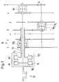
- FIG. 1 shows schematically an inventive double clutch transmission 10, which essentially corresponds to the double clutch transmission according to FIG. 1 of the earlier German patent application. Only the RG 1 and RG 2 friction gearboxes have been left out for the sake of clarity.
- the dual clutch transmission 10 is driven by an internal combustion engine, which is symbolized by its crankshaft 12.
- Two clutches K 1 and K 2 have a common outer clutch basket 14 and are arranged concentrically next to one another.
- a (first) transmission input shaft E 1 and another (second) transmission input shaft E 2 are connected to the respective friction plate 16 1 and 16 2 .
- the transmission input shaft E 2 is designed as a hollow shaft and surrounds the transmission input shaft E 1 .
- a total of six gear pairs 1 to 6 represent the individual gears.
- the drive wheels of gears 5 and 2 are firmly connected to the respective transmission input shaft, while the drive wheels of gears 1, 3, 4 and 6 are designed as needle-bearing idler gears which can be actuated by claws via sliding sleeves 18 1 and 18 2 .
- a transmission output shaft A carries a total of six output gears, the output gears of gears 5 and 2 being designed as idler gears and can be shifted via two independent sliding sleeves 18 3 and 18 4 .
- the driven wheels of gears 1, 3, 4 and 6 are firmly connected to the transmission output shaft A.
- the power flow runs via the closed clutch K 2 , the transmission input shaft E 2 , the sliding sleeve 18 2 , the drive gear of the first gear on the driven gear of the first gear on the transmission output shaft A.
- the clutch which transmits the engine power in the initial state, ie is essentially in the engaged state, ie in the static friction, is the “one” clutch, while the clutch carrying the auxiliary gear is the “other” clutch .
- the shift mode according to the present additional application has the source gear and target gear on the same transmission input shaft, in the examples shown on the transmission input shaft E 1 . However, there should be no restriction associated with this choice.
- the lower gear is always the one with the higher gearbox input speed.
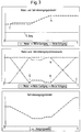
- Figure 2 shows the upshift in the train, ie the engine delivers a positive torque to the transmission.
- the transmission is initially operated in second gear, ie the clutch of the lower gear 2, K 1 , is in static friction.
- the target gear should be gear 4, ie one gear step should be skipped.
- Gear 4 is located on the same transmission input shaft E 1 , so that the method described in the older German patent application cannot be used.
- the flow of force flows - cf. 1 - from the internal combustion engine 12 via the clutch K 1 to the transmission input shaft E 1 , via the gear pairing of the second gear and the sliding sleeve 18 4 to the transmission output shaft A.
- the fifth gear is already switched as an auxiliary gear, ie the sliding sleeve 18 3 is also switched to the locking position, ie to the left in FIG. 1. It is, so to speak, a predictive "stocking" of the fifth gear as an auxiliary gear, in the event that the driver does not want to change from the second to the third gear according to the shifting procedure of the older German patent application, but instead wants to skip to the fourth gear to have the fifth gear immediately available as an auxiliary gear.
- the transmission input shaft E 2 thus rotates without torque when the clutch K 2 is open, driven via the fifth gear.
- the second gear can now be made torque-free by shifting the engine torque to the fifth gear, which is already engaged, by cleverly controlling the clutches K 1 and K 2 .
- the alternative process steps are described in subclaims 2 and 3.
- the entire engine torque has been shifted from the clutch K 1 of the second gear to the clutch K 2 of the fifth gear, ie the clutch K 1 , the "one" clutch, has no torque while the '' other '' clutch transmits the entire engine torque.
- the second gear can now be removed without torque, ie without jerk.
- the transmission output torque has decreased in accordance with the changed transmission ratio between second and fifth gear, as the lower illustration in FIG. 2 shows.
- the transmission output torque has not completely collapsed, as is the case with conventional manual transmissions, but a supporting torque or "filling torque" is still supplied by the fifth gear as an auxiliary gear.
- the transmission input shaft E 1 is brought to the synchronous speed of the fourth gear.
- the clutch K 1 is completely closed again.
- the clutch K 1 thus creates a connection between the transmission input shaft E 1 and the crankshaft 12, so that the transmission input shaft E 1 rotates at engine speed.
- the motor is braked, corresponding to a negative moment on the transmission input shaft E 1 , which is accelerated negatively, ie is braked.
- the middle representation in FIG. 2 shows that the torque applied to the shaft of the source gear, ie in the present example to the transmission input shaft E 1 , becomes negative, ie the shaft is braked.
- the transmission input shaft E 1 has reached the synchronous speed of the fourth gear, the fourth gear can be engaged without torque - as the middle illustration in FIG. 2 shows.
- the relationship between the upper and middle representation in FIG. 2 shows another connection that is essential to the invention: the slope of the curve of the transmission input speed in the upper representation between the speeds of the second and fourth gears corresponds to a gradient, ie a dw / dt. This gradient is proportional to the braking torque acting on the transmission input shaft in the middle representation between times b and c. A measure of the braking torque and therefore a control strategy for the clutch K 2 can therefore be derived from the necessary gradient between the speeds of the second and fourth gear. Corresponding control strategies are conceivable in extensive modifications and all fall within the scope of this invention.
- the clutch K 2 is opened abruptly by a certain actuating distance, which is equivalent to a negative torque jump, which in turn corresponds to a positive torque jump at the transmission input shaft E 1 , since the engine torque is shifted from the clutch K 2 back to the clutch K 1 . It has been found that such a jump in moment is particularly useful when shifting up. Then, at time e, clutch K 2 is opened continuously in a ramp-like manner until all of the engine torque that is supplied by crankshaft 12 is again transmitted to clutch 4 via clutch K 1 .
- FIG. 3 shows an example of the case of downshifting from fourth to second gear, the third gear should be skipped.
- the clutch K 1 is brought into sliding friction at time f and regulated to a desired speed, corresponding to a slight increase in the engine speed in the upper illustration in FIG. 3.
- By slowly controlled or regulated closing of the clutch K 2 - during the Clutch K 1 is further regulated to the same speed - the engine torque - as the middle illustration in FIG. 3 shows - is continuously shifted from clutch K 1 to clutch K 2 until clutch K 1 is momentless at time g and the fourth Gear can be removed without jerk by appropriately releasing the sliding sleeve 18 1 .
- the clutch K 1 is then closed again, so that the transmission input shaft E 1 rotates at engine speed. It is now necessary to accelerate the transmission input shaft E 1 to the synchronous speed of the second gear in order to be able to engage the same. For this purpose, the clutch K 2 is opened further, so that when the power control element of the motor remains unchanged, this increases its speed. In addition, the rotational energy stored in the entire moment of inertia of the motor is converted into higher speeds.
- clutch K 2 After engaging fourth gear at time h, clutch K 2 is opened in a ramp-like manner, corresponding to a continuously decreasing transferable engine torque. At time i, the entire engine torque has again been shifted from clutch K 2 to clutch K 1 - which drives the transmission input shaft E 1 .
- gear 1 also shows an alternative embodiment of the transmission according to the invention, in which only gears 2 and 6 are arranged on the “other" transmission input shaft E 2.
- the fourth gear is also intended as gear 4 ', as shown in dashed lines, on the "" one "Transmission input shaft E 1 may be arranged.
Landscapes
- Engineering & Computer Science (AREA)
- Mechanical Engineering (AREA)
- Transportation (AREA)
- General Engineering & Computer Science (AREA)
- Chemical & Material Sciences (AREA)
- Combustion & Propulsion (AREA)
- Automation & Control Theory (AREA)
- Structure Of Transmissions (AREA)
- Control Of Transmission Device (AREA)
Applications Claiming Priority (4)
| Application Number | Priority Date | Filing Date | Title |
|---|---|---|---|
| DE19631983 | 1996-08-08 | ||
| DE19631983A DE19631983C1 (de) | 1996-08-08 | 1996-08-08 | Verfahren zum Schalten eines Doppelkupplungsgetriebes und Doppelkupplungsgetriebe mit Synchronisiereinrichtung |
| DE19711820 | 1997-03-21 | ||
| DE19711820A DE19711820A1 (de) | 1996-08-08 | 1997-03-21 | Verfahren zum Schalten eines Doppelkupplungsgetriebes und Doppelkupplungsgetriebe |
Publications (3)
| Publication Number | Publication Date |
|---|---|
| EP0827861A2 true EP0827861A2 (fr) | 1998-03-11 |
| EP0827861A3 EP0827861A3 (fr) | 1998-09-09 |
| EP0827861B1 EP0827861B1 (fr) | 2003-01-29 |
Family
ID=26028228
Family Applications (1)
| Application Number | Title | Priority Date | Filing Date |
|---|---|---|---|
| EP97111500A Expired - Lifetime EP0827861B1 (fr) | 1996-08-08 | 1997-07-08 | Procédé de changement de vitesses d'une boîte de vitesses à double embrayage et transmission à double embrayage |
Country Status (4)
| Country | Link |
|---|---|
| US (2) | US5915512A (fr) |
| EP (1) | EP0827861B1 (fr) |
| JP (1) | JPH1089457A (fr) |
| DE (2) | DE19711820A1 (fr) |
Cited By (11)
| Publication number | Priority date | Publication date | Assignee | Title |
|---|---|---|---|---|
| DE19853824A1 (de) * | 1998-11-21 | 2000-05-31 | Getrag Getriebe Zahnrad | Automatisierbarer Kraftfahrzeug-Antriebsstrang sowie Verfahren zum Steuern eines solchen Antriebsstranges |
| DE19937716C1 (de) * | 1999-08-10 | 2000-11-30 | Daimler Chrysler Ag | Doppelkupplungs-Mehrganggetriebe |
| DE19924501A1 (de) * | 1999-05-28 | 2000-12-28 | Daimler Chrysler Ag | Lastschaltbares Stufenwechselgetriebe |
| DE19940288C1 (de) * | 1999-08-25 | 2001-03-15 | Daimler Chrysler Ag | Doppelkupplungs-Mehrganggetriebe |
| US6941830B2 (en) | 2000-03-10 | 2005-09-13 | Hitachi, Ltd. | Automatic transmission, dynamo-electric machine, and car |
| WO2007017012A1 (fr) * | 2005-07-30 | 2007-02-15 | Volkswagen Aktiengesellschaft | Procede pour commander des processus de changement de rapport dans des automobiles equipees d'une boite de vitesses a double embrayage |
| EP1479945A3 (fr) * | 2003-05-23 | 2009-11-11 | LuK Lamellen und Kupplungsbau Beteiligungs KG | Transmission à changement de vitesse sous puissance et dispositif de détection du couple d'embrayage et méthode de commande d'une rétrogradation en décéleration |
| DE102010011241A1 (de) * | 2010-03-12 | 2011-09-15 | GM Global Technology Operations LLC , (n. d. Ges. d. Staates Delaware) | Schaltverfahren für ein Doppelkupplungsgetriebe für Fahrzeuge |
| US8286522B2 (en) | 2009-04-14 | 2012-10-16 | GM Global Technology Operations LLC | Dual clutch transmission |
| DE102016114087A1 (de) | 2015-08-07 | 2017-02-09 | Avl List Gmbh | Verfahren zur Durchführung von Schaltvorgängen in einem Fahrzeugantriebsstrang |
| CN115451085A (zh) * | 2022-10-12 | 2022-12-09 | 赵克中 | 一种带扭变档装置及电动汽车 |
Families Citing this family (110)
| Publication number | Priority date | Publication date | Assignee | Title |
|---|---|---|---|---|
| US6044931A (en) * | 1998-09-15 | 2000-04-04 | Chrysler Corporation | Lubrication system for an automatic transmission having dual input shafts |
| DE19912315C1 (de) * | 1999-03-19 | 2000-11-02 | Daimler Chrysler Ag | Zahnräderwechselgetriebe mit zwei in bezug auf den Kraftfluß parallelen Teilgetrieben und Verfahren zum Schalten eines Zahnräderwechselgetriebes |
| DE19931160A1 (de) * | 1999-07-06 | 2001-01-11 | Volkswagen Ag | Verfahren und Vorrichtung zur Kupplungskennlinienadaption und zur Bestimmung eines kupplungsabhängigen Drehzahlgradienten |
| DE10034745B4 (de) | 1999-08-02 | 2012-08-30 | Schaeffler Technologies Gmbh & Co. Kg | Vorrichtung zum Betätigen zweier Kupplungen |
| DE19950679B4 (de) * | 1999-10-21 | 2010-01-07 | Volkswagen Ag | Automatisiertes Doppelkupplungsgetriebe und Verfahren zur Steuerung eines automatisierten Doppelkupplungsgetriebes |
| DE19952535B4 (de) | 1999-10-30 | 2011-07-28 | Volkswagen AG, 38440 | Automatisiertes Lastschaltgetriebe und Verfahren zur Steuerung eines automatisierten Lastschaltgetriebes |
| GB2384036B (en) * | 2000-02-15 | 2004-11-10 | Luk Lamellen & Kupplungsbau | Torque transmission device with double clutch transmission |
| US6397692B1 (en) * | 2000-02-18 | 2002-06-04 | Daimlerchrysler Corporation | Electro-mechanical automatic transmission for front wheel drive |
| FR2810706B1 (fr) * | 2000-06-22 | 2002-10-25 | Peugeot Citroen Automobiles Sa | Transmission du type a double embrayage |
| FR2810708B1 (fr) * | 2000-06-22 | 2002-10-25 | Peugeot Citroen Automobiles Sa | Dispositif de transmission et de maintien du couple |
| FR2810705B1 (fr) * | 2000-06-22 | 2002-10-31 | Peugeot Citroen Automobiles Sa | Dispositif de transmission et de maintien du couple |
| FR2810709B1 (fr) * | 2000-06-22 | 2002-10-25 | Peugeot Citroen Automobiles Sa | Dispositif de transmission et de maintien du couple notamment pour vehicule automobile |
| FR2810707B1 (fr) * | 2000-06-22 | 2002-10-25 | Peugeot Citroen Automobiles Sa | Dispositif de transmission et de maintien du couple |
| JP3293613B2 (ja) * | 2000-06-23 | 2002-06-17 | 株式会社日立製作所 | 自動車用制御装置,自動車の制御方法,変速機 |
| EP1544512B1 (fr) * | 2001-01-12 | 2008-03-05 | ZF Sachs AG | Véhicule avec une chaîne de traction ayant un dispositif à embrayages multiples |
| JP2002276797A (ja) * | 2001-03-15 | 2002-09-25 | Hitachi Ltd | 自動変速機 |
| JP3598998B2 (ja) | 2001-06-01 | 2004-12-08 | 日産自動車株式会社 | ツィンクラッチ式歯車変速機の歯車打音防止装置 |
| US6463821B1 (en) | 2001-06-29 | 2002-10-15 | Daimlerchrysler Corporation | Method of controlling a transmission having a dual clutch system |
| JP2003120763A (ja) * | 2001-10-17 | 2003-04-23 | Aichi Mach Ind Co Ltd | 変速機 |
| DE10151260A1 (de) | 2001-10-17 | 2003-04-30 | Zahnradfabrik Friedrichshafen | Verfahren zur Steuerung eines Doppelkupplungsgetriebes |
| JP2003139204A (ja) * | 2001-10-31 | 2003-05-14 | Aichi Mach Ind Co Ltd | 変速機 |
| JP3595296B2 (ja) * | 2001-11-06 | 2004-12-02 | 本田技研工業株式会社 | 動力伝達装置 |
| DE10390837D2 (de) * | 2002-03-07 | 2005-06-02 | Luk Lamellen & Kupplungsbau | Doppelkupplungsgetriebe und ein Verfahren zum Durchführen einer Hochschaltung von einem Anfangsgang in einen Zielgang bei dem Doppelkupplungsgetriebe eines Fahrzeuges |
| JP3738740B2 (ja) | 2002-03-19 | 2006-01-25 | 日産自動車株式会社 | ツインクラッチ式歯車変速機 |
| EP1353095A1 (fr) * | 2002-04-10 | 2003-10-15 | Van Doorne's Transmissie B.V. | Méthode de commande pour une transmission automatique |
| US6528458B1 (en) | 2002-04-19 | 2003-03-04 | The Lubrizol Corporation | Lubricant for dual clutch transmission |
| DE10243278A1 (de) * | 2002-09-18 | 2004-03-25 | Volkswagen Ag | Vorrichtung zur Synchronisierung eines Doppelkupplungsgetriebes |
| AU2003281912A1 (en) * | 2002-09-25 | 2004-04-19 | Luk Lamellen Und Kupplungsbau Beteiligungs Kg | Gear-shifting strategy and control system for a gearbox, especially for a twin-clutch gearbox |
| US6883394B2 (en) | 2002-10-15 | 2005-04-26 | Borgwarner, Inc. | Method for controlling the positioning of the synchronizers of a dual clutch transmission |
| US6715597B1 (en) | 2002-10-25 | 2004-04-06 | Borgwarner, Inc. | Dual clutch transmission clutch cooling control method |
| DE10253259A1 (de) * | 2002-11-15 | 2004-05-27 | Zf Friedrichshafen Ag | Universell gestaltbares Kraftfahrzeuggetriebe |
| DE10253616B4 (de) | 2002-11-15 | 2019-03-21 | Volkswagen Ag | Automatisiertes Doppelkupplungsgetriebe und Steuerungsverfahren für ein automatisiertes Doppelkupplungsgetriebe |
| DE10261872A1 (de) | 2002-12-20 | 2004-07-01 | Volkswagen Ag | Verfahren zur Schaltsteuerung eines automatisierten Doppelkupplungsgetriebes |
| EP1447597A2 (fr) * | 2003-02-11 | 2004-08-18 | LuK Lamellen und Kupplungsbau Beteiligungs KG | Procédé et mechanisme de changement de rapport d'une transmission à rapport variable sous charge comprise dans la chaine cinématique d'un véhicule |
| US6819997B2 (en) * | 2003-02-21 | 2004-11-16 | Borgwarner, Inc. | Method of controlling a dual clutch transmission |
| US6832978B2 (en) * | 2003-02-21 | 2004-12-21 | Borgwarner, Inc. | Method of controlling a dual clutch transmission |
| EP1450075B1 (fr) * | 2003-02-21 | 2013-12-04 | BorgWarner, Inc. | Procédé de commande d'une transmission à deux embrayages |
| US6790159B1 (en) * | 2003-02-21 | 2004-09-14 | Borgwarner, Inc. | Method of controlling a dual clutch transmission |
| US6869382B2 (en) | 2003-05-07 | 2005-03-22 | Daimlerchrysler Corporation | Double-downshift gear strategy for a dual clutch automatic transmission |
| US6880418B2 (en) * | 2003-06-25 | 2005-04-19 | Ford Global Technologies, Llc | Method for controlling speed ratio changes in a layshaft automatic transmission having power-on shifting |
| US6886424B2 (en) * | 2003-06-25 | 2005-05-03 | Ford Global Technologies, Llc | Layshaft automatic transmission having power-on shifting |
| DE10349220B4 (de) * | 2003-07-16 | 2014-09-11 | Volkswagen Ag | Verfahren zum Schalten eines Doppelkupplungsgetriebes eines Kraftfahrzeuges |
| WO2005008103A1 (fr) * | 2003-07-16 | 2005-01-27 | Volkswagen Aktiengesellschaft | Procede de commutation d'une boite de vitesses a double embrayage d'automobile |
| US6898992B2 (en) * | 2003-08-08 | 2005-05-31 | Borgwarner, Inc. | Method for controlling the engagement force of the synchronizers of a dual clutch transmission |
| DE50302896D1 (de) * | 2003-08-14 | 2006-05-18 | Getrag Ford Transmissions Gmbh | Verfahren zum Schalten von zwei Kupplungen |
| DE10343995B4 (de) * | 2003-09-23 | 2014-03-06 | Zf Friedrichshafen Ag | Getriebestruktur |
| EP1522762A3 (fr) * | 2003-10-06 | 2010-03-10 | Borgwarner, Inc. | Système d'embrayages multiples à système de sortie mixte pour transmission de train moteur |
| US6953417B2 (en) * | 2003-11-17 | 2005-10-11 | Borgwarner Inc. | Method for controlling a dual clutch transmission |
| CN100392289C (zh) * | 2004-01-16 | 2008-06-04 | 杨庆民 | 无动力中断的自动换档离偶合器式变速器 |
| US7510506B2 (en) * | 2004-02-10 | 2009-03-31 | Luk Lamellen Und Kupplungabau Beteiligungs Kg | Method and device for controlling gear ratio change in a transmission contained in the drive train of a motor vehicle with gears that can be shifted under power |
| JP2006002917A (ja) * | 2004-06-21 | 2006-01-05 | Aisin Ai Co Ltd | 複数のクラッチを持つ変速装置 |
| US7311187B2 (en) * | 2004-07-07 | 2007-12-25 | Borgwarner Inc. | Dual clutch transmission clutch cooling circuit |
| US20060006042A1 (en) * | 2004-07-07 | 2006-01-12 | Melissa Koenig | Dual clutch transmission clutch cooling circuit |
| US7127961B2 (en) * | 2004-07-09 | 2006-10-31 | Borgwarner Inc. | Integrated control module for a dual clutch transmission |
| US7073407B2 (en) * | 2004-07-09 | 2006-07-11 | Borgwarner Inc. | Integrated control module for use in a dual clutch transmission having integrated shift actuator position sensors |
| JP2006029476A (ja) * | 2004-07-16 | 2006-02-02 | Nissan Motor Co Ltd | 駆動力伝達装置 |
| JP2006038161A (ja) * | 2004-07-29 | 2006-02-09 | Aisin Ai Co Ltd | クラッチを持つ変速装置 |
| US7155993B2 (en) * | 2004-11-15 | 2007-01-02 | Borgwarner Inc. | Dual clutch transmission having a synchronizer actuation interlock circuit |
| KR100993520B1 (ko) | 2004-12-15 | 2010-11-10 | 현대자동차주식회사 | 더블클러치 트랜스미션의 다운시프트 제어방법 |
| DE102005006567A1 (de) * | 2005-02-11 | 2006-08-24 | Volkswagen Ag | Verfahren zur Realisierung der Schaltungen von einem Quellgang in einen Zielgang eines Doppelkupplungsgetriebes |
| GB0504628D0 (en) * | 2005-03-05 | 2005-04-13 | Zeroshift Ltd | Transmission layout |
| US20060225527A1 (en) * | 2005-04-06 | 2006-10-12 | Ching-Min Yang | Automatic transmission using a shift support system |
| GB0510129D0 (en) * | 2005-05-18 | 2005-06-22 | Zeroshift Ltd | Sequential hub layout |
| US7384374B2 (en) * | 2005-12-16 | 2008-06-10 | Ford Global Technologies, Llc | Tip-in/tip-out gear shift control for a powershift automatic transmission |
| KR20080111102A (ko) * | 2006-04-28 | 2008-12-22 | 루크 라멜렌 운트 쿠프룽스바우 베타일리궁스 카게 | 더블 클러치 변속기의 클러치 제어 적응 방법 및 그 장치 |
| US7469609B2 (en) * | 2006-06-28 | 2008-12-30 | Ford Global Technologies, Llc | Output reduction dual clutch transmission with clutch coupler |
| US20080000980A1 (en) * | 2006-06-29 | 2008-01-03 | Benjamin Hejl | Audible scan indicator |
| DE102006034091A1 (de) * | 2006-07-20 | 2008-01-24 | Ricardo Deutschland Gmbh | Vorrichtung zur Übertragung und/oder Beeinflussung eines Drehmoments einer Welle |
| DE102006045521B4 (de) * | 2006-09-27 | 2015-01-08 | Audi Ag | Verfahren zum Umschalten einer Hybridantriebsvorrichtung |
| GB0623292D0 (en) * | 2006-11-22 | 2007-01-03 | Zeroshift Ltd | Transmission system |
| DE102006058947A1 (de) * | 2006-12-14 | 2008-06-19 | Dr.Ing.H.C. F. Porsche Ag | Doppelkupplung für einen Hybrid-Antrieb |
| US8387476B2 (en) * | 2007-03-02 | 2013-03-05 | Borgwarner Inc. | Hydraulic actuation valve arrangement for dual clutch transmission |
| JP4810472B2 (ja) | 2007-03-12 | 2011-11-09 | 愛知機械工業株式会社 | ツインクラッチ式変速機 |
| US7861613B2 (en) * | 2007-04-17 | 2011-01-04 | Eaton Corporation | Selector mechanism for dual-clutch transmissions |
| DE102007029634A1 (de) * | 2007-06-26 | 2009-01-08 | Daimler Ag | Zahnräderwechselgetriebe |
| CN101918740B (zh) * | 2007-07-26 | 2014-06-11 | 格特拉格传动机构和齿轮工厂赫尔曼·哈根迈尔有限公司&两合公司 | 用于控制在双离合器变速器中的升档过程的方法 |
| CN101946105B (zh) * | 2008-03-04 | 2013-07-17 | 博格华纳公司 | 具有区域控制的离合器冷却回路的双离合器变速器 |
| EP2105385A1 (fr) | 2008-03-25 | 2009-09-30 | Philip Morris Products S.A. | Paquet pour articles à fumer |
| DE102008001199B4 (de) * | 2008-04-16 | 2018-12-20 | Zf Friedrichshafen Ag | Verfahren zum Betreiben eines Doppelkupplungsgetriebes |
| JP2009257522A (ja) * | 2008-04-18 | 2009-11-05 | Mitsubishi Electric Corp | トランスミッション制御装置 |
| US8968136B2 (en) | 2008-04-18 | 2015-03-03 | Borgwarner Inc. | Dual clutch transmission having simplified controls |
| US8376906B2 (en) | 2008-12-09 | 2013-02-19 | Borgwarner Inc. | Automatic transmission for a hybrid vehicle |
| US8511189B2 (en) * | 2008-12-17 | 2013-08-20 | GM Global Technology Operations LLC | Dual clutch multi-speed transmission |
| US8220351B2 (en) * | 2009-03-20 | 2012-07-17 | GM Global Technology Operations LLC | Dual clutch multi-speed transmission having one countershaft and a reverse shaft |
| CN102459965B (zh) | 2009-06-29 | 2014-11-05 | 博格华纳公司 | 用于在自动变速器控制模块中使用的液压阀 |
| US8820185B2 (en) * | 2009-12-03 | 2014-09-02 | Gm Global Technology Operations, Llc | Control system for a dual clutch transmission |
| US8590684B2 (en) * | 2009-12-03 | 2013-11-26 | GM Global Technology Operations LLC | Control system for a dual clutch transmission |
| CN102652235B (zh) | 2009-12-31 | 2014-11-12 | 博格华纳公司 | 具有高压致动和低压润滑液压回路的自动变速器 |
| US8504263B2 (en) * | 2010-04-23 | 2013-08-06 | GM Global Technology Operations LLC | Accumulator working volume management and adaptation |
| US8308609B2 (en) | 2010-06-14 | 2012-11-13 | Ford Global Technologies, Llc | Power-off downshift engagement dampening |
| US8844390B2 (en) * | 2010-10-13 | 2014-09-30 | Hyundai Wia Corporation | Dual clutch transmission and dual clutch accuators thereof |
| DE102010042656B4 (de) * | 2010-10-20 | 2022-06-23 | Zf Friedrichshafen Ag | Lastschaltbares Getriebe |
| US8839928B2 (en) | 2010-12-02 | 2014-09-23 | Gm Global Technology Operations, Llc | Electro-hydraulic control system for a dual clutch transmission |
| US8733521B2 (en) | 2010-12-06 | 2014-05-27 | Gm Global Technology Operations | Apparatus for and method of controlling a dual clutch transmission |
| US8904893B2 (en) | 2010-12-06 | 2014-12-09 | Gm Global Technology Operations, Llc | Method of controlling a dual clutch transmission |
| US8740748B2 (en) | 2010-12-08 | 2014-06-03 | Gm Global Technology Operations, Llc | Control system and method for a dual clutch transmission |
| US8738257B2 (en) | 2010-12-08 | 2014-05-27 | Gm Global Technology Operations, Llc | Electro-hydraulic control system and method for a dual clutch transmission |
| US8702564B2 (en) | 2010-12-09 | 2014-04-22 | GM Global Technology Operations LLC | Electro-hydraulic control system and method for a dual clutch transmission |
| DE102011006004A1 (de) * | 2011-03-24 | 2012-09-27 | Zf Friedrichshafen Ag | Verfahren zur Synchronisierung eines Doppelkupplungsgetriebes und Doppelkupplungsgetriebe |
| KR101310064B1 (ko) * | 2011-04-26 | 2013-09-24 | 현대 파워텍 주식회사 | 리턴스프링을 공용화한 듀얼 클러치 변속기의 변속 제어 방법 |
| GB201109100D0 (en) | 2011-05-27 | 2011-07-13 | Zeroshift Ltd | Transmission system |
| KR101316314B1 (ko) * | 2011-06-09 | 2013-10-08 | 기아자동차주식회사 | 차량의 dct 제어방법 |
| KR101305852B1 (ko) | 2011-06-09 | 2013-09-06 | 현대자동차주식회사 | 차량의 변속기 제어방법 |
| KR101305842B1 (ko) | 2011-06-09 | 2013-09-06 | 기아자동차주식회사 | 차량의 더블클러치변속기 제어방법 |
| JP5439555B2 (ja) * | 2012-08-08 | 2014-03-12 | 富士重工業株式会社 | 変速機 |
| KR101897295B1 (ko) * | 2012-10-11 | 2018-10-22 | 현대자동차주식회사 | 자동화 수동변속기의 동기 제어방법 |
| DE102014206303A1 (de) * | 2014-04-02 | 2015-10-08 | Schaeffler Technologies AG & Co. KG | Getriebe |
| KR101655287B1 (ko) * | 2014-12-05 | 2016-09-07 | 현대오트론 주식회사 | 듀얼 클러치 변속기의 슬립 스타트 제어 방법 |
| IT201800007500A1 (it) * | 2018-07-25 | 2020-01-25 | Ducati Motor Holding Spa | Cambio Seamless |
| DE102023206266B3 (de) * | 2023-07-03 | 2024-12-24 | Zf Friedrichshafen Ag | Verfahren zum Schalten eines lastschaltbaren Kraftfahrzeuggetriebes, ein lastschaltbares Kraftfahrzeuggetriebe und landwirtschaftliches Nutzfahrzeug |
Family Cites Families (15)
| Publication number | Priority date | Publication date | Assignee | Title |
|---|---|---|---|---|
| DE443626C (de) * | 1925-05-24 | 1927-05-05 | Telefunken Gmbh | Einrichtung zum stoerungsfreien Empfang in der Hochfrequenznachrichtenuebermittlung |
| GB1537704A (en) * | 1976-02-14 | 1979-01-04 | Brown Tractors Ltd | Clutches |
| US4463621A (en) * | 1981-12-23 | 1984-08-07 | Ford Motor Company | Multiple countershaft automatic transmission |
| US4513631A (en) * | 1983-06-16 | 1985-04-30 | General Motors Corporation | Dual input clutch transmission |
| DE3417504A1 (de) * | 1984-05-11 | 1985-11-14 | J.M. Voith Gmbh, 7920 Heidenheim | Stufenschaltgetriebe, insbesondere fuer kraftfahrzeuge |
| SE451005B (sv) * | 1985-03-28 | 1987-08-24 | Volvo Ab | Motorfordonsvexellada |
| JP2791660B2 (ja) * | 1987-04-10 | 1998-08-27 | 株式会社小松製作所 | 変速機の制御装置 |
| US4979599A (en) * | 1988-02-09 | 1990-12-25 | Kubota, Ltd. | Work vehicle |
| DE4017961A1 (de) * | 1989-06-10 | 1990-12-13 | Zahnradfabrik Friedrichshafen | Steuersystem fuer ein lastschaltbares doppel-kupplungsgetriebe |
| US4966048A (en) * | 1989-08-17 | 1990-10-30 | Eaton Corporation | Manual transmission and shift control therefor |
| DE4031570C2 (de) * | 1990-10-05 | 1995-10-12 | Daimler Benz Ag | Anordnung zum selbsttätigen Schalten mittels Druckmittel-Hilfskraft eines Mehrwege-Zahnräderwechselgetriebes |
| JP3161853B2 (ja) * | 1993-01-20 | 2001-04-25 | 株式会社クボタ | 作業車の走行変速構造 |
| IT1266918B1 (it) * | 1994-08-09 | 1997-01-21 | New Holland Fiat Spa | Cambio di velocita' per un veicolo, particolarmente un trattore agricolo. |
| JP3531301B2 (ja) * | 1995-07-25 | 2004-05-31 | トヨタ自動車株式会社 | ツインクラッチ式変速機 |
| US5823051A (en) * | 1997-05-05 | 1998-10-20 | General Motors Corporation | Multi-speed power transmission |
-
1997
- 1997-03-21 DE DE19711820A patent/DE19711820A1/de not_active Withdrawn
- 1997-07-08 DE DE59709216T patent/DE59709216D1/de not_active Expired - Lifetime
- 1997-07-08 EP EP97111500A patent/EP0827861B1/fr not_active Expired - Lifetime
- 1997-07-30 US US08/903,378 patent/US5915512A/en not_active Expired - Lifetime
- 1997-08-07 JP JP9213591A patent/JPH1089457A/ja active Pending
-
1998
- 1998-10-27 US US09/181,016 patent/US5950781A/en not_active Expired - Lifetime
Cited By (15)
| Publication number | Priority date | Publication date | Assignee | Title |
|---|---|---|---|---|
| DE19853824A1 (de) * | 1998-11-21 | 2000-05-31 | Getrag Getriebe Zahnrad | Automatisierbarer Kraftfahrzeug-Antriebsstrang sowie Verfahren zum Steuern eines solchen Antriebsstranges |
| DE19924501A1 (de) * | 1999-05-28 | 2000-12-28 | Daimler Chrysler Ag | Lastschaltbares Stufenwechselgetriebe |
| DE19937716C1 (de) * | 1999-08-10 | 2000-11-30 | Daimler Chrysler Ag | Doppelkupplungs-Mehrganggetriebe |
| DE19940288C1 (de) * | 1999-08-25 | 2001-03-15 | Daimler Chrysler Ag | Doppelkupplungs-Mehrganggetriebe |
| US6941830B2 (en) | 2000-03-10 | 2005-09-13 | Hitachi, Ltd. | Automatic transmission, dynamo-electric machine, and car |
| US7093512B2 (en) | 2000-03-10 | 2006-08-22 | Hitachi, Ltd. | Automatic transmission, dynamo-electric machine, and car |
| US7476176B2 (en) | 2000-03-10 | 2009-01-13 | Hitachi, Ltd. | Automatic transmission, dynamo-electric machine, and car |
| EP1479945A3 (fr) * | 2003-05-23 | 2009-11-11 | LuK Lamellen und Kupplungsbau Beteiligungs KG | Transmission à changement de vitesse sous puissance et dispositif de détection du couple d'embrayage et méthode de commande d'une rétrogradation en décéleration |
| WO2007017012A1 (fr) * | 2005-07-30 | 2007-02-15 | Volkswagen Aktiengesellschaft | Procede pour commander des processus de changement de rapport dans des automobiles equipees d'une boite de vitesses a double embrayage |
| US8286522B2 (en) | 2009-04-14 | 2012-10-16 | GM Global Technology Operations LLC | Dual clutch transmission |
| DE102010011241A1 (de) * | 2010-03-12 | 2011-09-15 | GM Global Technology Operations LLC , (n. d. Ges. d. Staates Delaware) | Schaltverfahren für ein Doppelkupplungsgetriebe für Fahrzeuge |
| DE102016114087A1 (de) | 2015-08-07 | 2017-02-09 | Avl List Gmbh | Verfahren zur Durchführung von Schaltvorgängen in einem Fahrzeugantriebsstrang |
| AT517581A4 (de) * | 2015-08-07 | 2017-03-15 | Avl List Gmbh | Verfahren zur durchführung von schaltvorgängen in einem fahrzeugantriebsstrang |
| AT517581B1 (de) * | 2015-08-07 | 2017-03-15 | Avl List Gmbh | Verfahren zur durchführung von schaltvorgängen in einem fahrzeugantriebsstrang |
| CN115451085A (zh) * | 2022-10-12 | 2022-12-09 | 赵克中 | 一种带扭变档装置及电动汽车 |
Also Published As
| Publication number | Publication date |
|---|---|
| EP0827861B1 (fr) | 2003-01-29 |
| US5915512A (en) | 1999-06-29 |
| JPH1089457A (ja) | 1998-04-07 |
| DE19711820A1 (de) | 1998-09-24 |
| US5950781A (en) | 1999-09-14 |
| EP0827861A3 (fr) | 1998-09-09 |
| DE59709216D1 (de) | 2003-03-06 |
Similar Documents
| Publication | Publication Date | Title |
|---|---|---|
| EP0827861B1 (fr) | Procédé de changement de vitesses d'une boîte de vitesses à double embrayage et transmission à double embrayage | |
| DE19631983C1 (de) | Verfahren zum Schalten eines Doppelkupplungsgetriebes und Doppelkupplungsgetriebe mit Synchronisiereinrichtung | |
| EP0845618B1 (fr) | Transmission à rapports étagés avec variation continue | |
| DE19717042C2 (de) | Verfahren zum Schalten eines synchronisiergliederfreien Zahnräderwechselgetriebes | |
| DE19950679A1 (de) | Automatisiertes Doppelkupplungsgetriebe und Verfahren zur Steuerung eines automatisierten Doppelkupplungsgetriebes | |
| DE4031851C2 (de) | Stufenwechselgetriebe | |
| DE19939819C1 (de) | Verfahren zum Schalten eines Mehrwege-Zahnräder-Wechselgetriebes | |
| EP1031769B1 (fr) | Boíte de vitesses robotisée pour véhicule et système de commande pour une telle boíte de vitesses | |
| DE19939334A1 (de) | Verfahren zum Schalten eines Doppelkupplungsgetriebes und Doppelkupplungsgetriebe | |
| EP1551662B1 (fr) | Procede de commande des changements de rapports d'une boite couplable sous charge et boite de vitesses couplable sous charge | |
| DE3037990A1 (de) | Zahnraedergetriebe | |
| WO2001088409A2 (fr) | Transmission comprenant un embrayage et procede pour actionner un embrayage | |
| DE10004530B4 (de) | Verfahren zur Steuerung eines Doppelkupplungsgetriebes | |
| DE10308517A1 (de) | Verfahren zur Kupplungskennlinienadaption | |
| DE102010041322A1 (de) | Verfahren zur Steuerung von Schaltungen eines Fahrzeuggetriebes | |
| DE19937716C1 (de) | Doppelkupplungs-Mehrganggetriebe | |
| DE19924501A1 (de) | Lastschaltbares Stufenwechselgetriebe | |
| DE10060699A1 (de) | Getriebe und Verfahren zum Betreiben eines Getriebes | |
| DE102015003407A1 (de) | Kraftfahrzeug mit einem Doppelkupplungsgetriebe | |
| DE102010035776B4 (de) | Ansteuerverfahren für Hybrid-Antriebsstrang | |
| EP1096172A2 (fr) | Transmission de changement de vitesse sous charge automatisée et sa méthode de commande | |
| EP0348732A2 (fr) | Méthode de synchronisation de vitesses rotatives | |
| DE19845604C5 (de) | Stufengetriebe und Verfahren zum Auslegen eines Ganges eines Stufengetriebes | |
| DE10063848A1 (de) | Stufenschaltgetriebe für ein Kraftfahrzeug | |
| EP1479945A2 (fr) | Transmission à changement de vitesse sous puissance et dispositif de détection du couple d'embrayage et méthode de commande d'une rétrogradation en décéleration |
Legal Events
| Date | Code | Title | Description |
|---|---|---|---|
| PUAI | Public reference made under article 153(3) epc to a published international application that has entered the european phase |
Free format text: ORIGINAL CODE: 0009012 |
|
| AK | Designated contracting states |
Kind code of ref document: A2 Designated state(s): DE ES FR GB IT |
|
| PUAL | Search report despatched |
Free format text: ORIGINAL CODE: 0009013 |
|
| AK | Designated contracting states |
Kind code of ref document: A3 Designated state(s): AT BE CH DE DK ES FI FR GB GR IE IT LI LU MC NL PT SE |
|
| 17P | Request for examination filed |
Effective date: 19990309 |
|
| AKX | Designation fees paid |
Free format text: DE ES FR GB IT |
|
| RBV | Designated contracting states (corrected) |
Designated state(s): DE ES FR GB IT |
|
| 17Q | First examination report despatched |
Effective date: 20001128 |
|
| GRAG | Despatch of communication of intention to grant |
Free format text: ORIGINAL CODE: EPIDOS AGRA |
|
| GRAG | Despatch of communication of intention to grant |
Free format text: ORIGINAL CODE: EPIDOS AGRA |
|
| GRAG | Despatch of communication of intention to grant |
Free format text: ORIGINAL CODE: EPIDOS AGRA |
|
| GRAH | Despatch of communication of intention to grant a patent |
Free format text: ORIGINAL CODE: EPIDOS IGRA |
|
| GRAH | Despatch of communication of intention to grant a patent |
Free format text: ORIGINAL CODE: EPIDOS IGRA |
|
| GRAA | (expected) grant |
Free format text: ORIGINAL CODE: 0009210 |
|
| AK | Designated contracting states |
Designated state(s): DE ES FR GB IT |
|
| PG25 | Lapsed in a contracting state [announced via postgrant information from national office to epo] |
Ref country code: IT Free format text: LAPSE BECAUSE OF FAILURE TO SUBMIT A TRANSLATION OF THE DESCRIPTION OR TO PAY THE FEE WITHIN THE PRE;WARNING: LAPSES OF ITALIAN PATENTS WITH EFFECTIVE DATE BEFORE 2007 MAY HAVE OCCURRED AT ANY TIME BEFORE 2007. THE CORRECT EFFECTIVE DATE MAY BE DIFFERENT FROM THE ONE RECORDED.SCRIBED TIME-LIMIT Effective date: 20030129 |
|
| REG | Reference to a national code |
Ref country code: GB Ref legal event code: FG4D Free format text: NOT ENGLISH |
|
| REF | Corresponds to: |
Ref document number: 59709216 Country of ref document: DE Date of ref document: 20030306 Kind code of ref document: P |
|
| GBT | Gb: translation of ep patent filed (gb section 77(6)(a)/1977) |
Effective date: 20030501 |
|
| PG25 | Lapsed in a contracting state [announced via postgrant information from national office to epo] |
Ref country code: ES Free format text: LAPSE BECAUSE OF FAILURE TO SUBMIT A TRANSLATION OF THE DESCRIPTION OR TO PAY THE FEE WITHIN THE PRESCRIBED TIME-LIMIT Effective date: 20030730 |
|
| ET | Fr: translation filed | ||
| PLBE | No opposition filed within time limit |
Free format text: ORIGINAL CODE: 0009261 |
|
| STAA | Information on the status of an ep patent application or granted ep patent |
Free format text: STATUS: NO OPPOSITION FILED WITHIN TIME LIMIT |
|
| 26N | No opposition filed |
Effective date: 20031030 |
|
| PGFP | Annual fee paid to national office [announced via postgrant information from national office to epo] |
Ref country code: FR Payment date: 20130730 Year of fee payment: 17 Ref country code: GB Payment date: 20130731 Year of fee payment: 17 |
|
| GBPC | Gb: european patent ceased through non-payment of renewal fee |
Effective date: 20140708 |
|
| REG | Reference to a national code |
Ref country code: FR Ref legal event code: ST Effective date: 20150331 |
|
| PG25 | Lapsed in a contracting state [announced via postgrant information from national office to epo] |
Ref country code: FR Free format text: LAPSE BECAUSE OF NON-PAYMENT OF DUE FEES Effective date: 20140731 Ref country code: GB Free format text: LAPSE BECAUSE OF NON-PAYMENT OF DUE FEES Effective date: 20140708 |
|
| PGFP | Annual fee paid to national office [announced via postgrant information from national office to epo] |
Ref country code: DE Payment date: 20150731 Year of fee payment: 19 |
|
| REG | Reference to a national code |
Ref country code: DE Ref legal event code: R119 Ref document number: 59709216 Country of ref document: DE |
|
| PG25 | Lapsed in a contracting state [announced via postgrant information from national office to epo] |
Ref country code: DE Free format text: LAPSE BECAUSE OF NON-PAYMENT OF DUE FEES Effective date: 20170201 |