EP0828052A2 - Hohlprofil, insbesondere aus Kunststoff mit Wärmeisolationsmittel - Google Patents
Hohlprofil, insbesondere aus Kunststoff mit Wärmeisolationsmittel Download PDFInfo
- Publication number
- EP0828052A2 EP0828052A2 EP97115430A EP97115430A EP0828052A2 EP 0828052 A2 EP0828052 A2 EP 0828052A2 EP 97115430 A EP97115430 A EP 97115430A EP 97115430 A EP97115430 A EP 97115430A EP 0828052 A2 EP0828052 A2 EP 0828052A2
- Authority
- EP
- European Patent Office
- Prior art keywords
- hollow profile
- profile according
- barrier film
- longitudinal side
- layer
- Prior art date
- Legal status (The legal status is an assumption and is not a legal conclusion. Google has not performed a legal analysis and makes no representation as to the accuracy of the status listed.)
- Granted
Links
- 239000004033 plastic Substances 0.000 title claims abstract description 64
- 229920003023 plastic Polymers 0.000 title claims abstract description 64
- 238000009413 insulation Methods 0.000 title claims abstract description 53
- 230000004888 barrier function Effects 0.000 claims abstract description 166
- 238000000034 method Methods 0.000 claims description 20
- 230000008569 process Effects 0.000 claims description 20
- 229910052751 metal Inorganic materials 0.000 claims description 19
- 239000002184 metal Substances 0.000 claims description 19
- 238000005192 partition Methods 0.000 claims description 16
- 238000001125 extrusion Methods 0.000 claims description 13
- 239000002984 plastic foam Substances 0.000 claims description 10
- BASFCYQUMIYNBI-UHFFFAOYSA-N platinum Chemical compound [Pt] BASFCYQUMIYNBI-UHFFFAOYSA-N 0.000 claims description 10
- VYZAMTAEIAYCRO-UHFFFAOYSA-N Chromium Chemical compound [Cr] VYZAMTAEIAYCRO-UHFFFAOYSA-N 0.000 claims description 7
- 229910052782 aluminium Inorganic materials 0.000 claims description 7
- XAGFODPZIPBFFR-UHFFFAOYSA-N aluminium Chemical compound [Al] XAGFODPZIPBFFR-UHFFFAOYSA-N 0.000 claims description 7
- 239000002131 composite material Substances 0.000 claims description 7
- 238000003780 insertion Methods 0.000 claims description 6
- 230000037431 insertion Effects 0.000 claims description 6
- 229910000906 Bronze Inorganic materials 0.000 claims description 5
- 239000010974 bronze Substances 0.000 claims description 5
- KUNSUQLRTQLHQQ-UHFFFAOYSA-N copper tin Chemical compound [Cu].[Sn] KUNSUQLRTQLHQQ-UHFFFAOYSA-N 0.000 claims description 5
- PCHJSUWPFVWCPO-UHFFFAOYSA-N gold Chemical compound [Au] PCHJSUWPFVWCPO-UHFFFAOYSA-N 0.000 claims description 5
- 239000010931 gold Substances 0.000 claims description 5
- 229910052737 gold Inorganic materials 0.000 claims description 5
- 230000035515 penetration Effects 0.000 claims description 5
- 229910052697 platinum Inorganic materials 0.000 claims description 5
- 229910052709 silver Inorganic materials 0.000 claims description 5
- 239000004332 silver Substances 0.000 claims description 5
- 239000004800 polyvinyl chloride Substances 0.000 claims description 4
- 229920000915 polyvinyl chloride Polymers 0.000 claims description 4
- 239000011324 bead Substances 0.000 claims description 2
- 229920000728 polyester Polymers 0.000 claims description 2
- 239000010410 layer Substances 0.000 claims 33
- 239000012790 adhesive layer Substances 0.000 claims 1
- 239000004922 lacquer Substances 0.000 claims 1
- 230000000149 penetrating effect Effects 0.000 claims 1
- 239000002985 plastic film Substances 0.000 claims 1
- 229920006255 plastic film Polymers 0.000 claims 1
- 239000000463 material Substances 0.000 description 22
- 230000002787 reinforcement Effects 0.000 description 19
- 238000012546 transfer Methods 0.000 description 19
- 238000012549 training Methods 0.000 description 17
- 230000005855 radiation Effects 0.000 description 16
- 239000011888 foil Substances 0.000 description 10
- 238000013461 design Methods 0.000 description 5
- 238000011161 development Methods 0.000 description 5
- 230000018109 developmental process Effects 0.000 description 5
- 230000000694 effects Effects 0.000 description 5
- 238000004519 manufacturing process Methods 0.000 description 5
- 230000003068 static effect Effects 0.000 description 4
- 230000002411 adverse Effects 0.000 description 3
- 230000008901 benefit Effects 0.000 description 3
- 238000010422 painting Methods 0.000 description 3
- 238000000926 separation method Methods 0.000 description 3
- 238000007740 vapor deposition Methods 0.000 description 3
- 238000005452 bending Methods 0.000 description 2
- 230000015572 biosynthetic process Effects 0.000 description 2
- 238000001816 cooling Methods 0.000 description 2
- 239000006260 foam Substances 0.000 description 2
- 230000014759 maintenance of location Effects 0.000 description 2
- 239000007769 metal material Substances 0.000 description 2
- 238000000465 moulding Methods 0.000 description 2
- 238000004064 recycling Methods 0.000 description 2
- 230000003014 reinforcing effect Effects 0.000 description 2
- 238000007789 sealing Methods 0.000 description 2
- 238000007493 shaping process Methods 0.000 description 2
- 208000031872 Body Remains Diseases 0.000 description 1
- 229920000049 Carbon (fiber) Polymers 0.000 description 1
- 238000004026 adhesive bonding Methods 0.000 description 1
- 238000004873 anchoring Methods 0.000 description 1
- 230000000712 assembly Effects 0.000 description 1
- 238000000429 assembly Methods 0.000 description 1
- 238000010009 beating Methods 0.000 description 1
- 230000002146 bilateral effect Effects 0.000 description 1
- 239000004917 carbon fiber Substances 0.000 description 1
- 230000008859 change Effects 0.000 description 1
- 230000006835 compression Effects 0.000 description 1
- 238000007906 compression Methods 0.000 description 1
- 238000009833 condensation Methods 0.000 description 1
- 230000005494 condensation Effects 0.000 description 1
- 238000010276 construction Methods 0.000 description 1
- 238000005520 cutting process Methods 0.000 description 1
- 238000004049 embossing Methods 0.000 description 1
- 238000001704 evaporation Methods 0.000 description 1
- 230000008020 evaporation Effects 0.000 description 1
- 238000005755 formation reaction Methods 0.000 description 1
- 230000005764 inhibitory process Effects 0.000 description 1
- 238000012423 maintenance Methods 0.000 description 1
- 238000005498 polishing Methods 0.000 description 1
- 238000012545 processing Methods 0.000 description 1
- 230000009467 reduction Effects 0.000 description 1
- 230000000087 stabilizing effect Effects 0.000 description 1
- 229920001169 thermoplastic Polymers 0.000 description 1
- 239000004416 thermosoftening plastic Substances 0.000 description 1
- 230000000007 visual effect Effects 0.000 description 1
- 230000037303 wrinkles Effects 0.000 description 1
Images


Classifications
-
- E—FIXED CONSTRUCTIONS
- E06—DOORS, WINDOWS, SHUTTERS, OR ROLLER BLINDS IN GENERAL; LADDERS
- E06B—FIXED OR MOVABLE CLOSURES FOR OPENINGS IN BUILDINGS, VEHICLES, FENCES OR LIKE ENCLOSURES IN GENERAL, e.g. DOORS, WINDOWS, BLINDS, GATES
- E06B3/00—Window sashes, door leaves, or like elements for closing wall or like openings; Layout of fixed or moving closures, e.g. windows in wall or like openings; Features of rigidly-mounted outer frames relating to the mounting of wing frames
- E06B3/04—Wing frames not characterised by the manner of movement
- E06B3/06—Single frames
- E06B3/08—Constructions depending on the use of specified materials
- E06B3/20—Constructions depending on the use of specified materials of plastics
- E06B3/22—Hollow frames
- E06B3/221—Hollow frames with the frame member having local reinforcements in some parts of its cross-section or with a filled cavity
- E06B3/222—Hollow frames with the frame member having local reinforcements in some parts of its cross-section or with a filled cavity with internal prefabricated reinforcing section members inserted after manufacturing of the hollow frame
-
- E—FIXED CONSTRUCTIONS
- E06—DOORS, WINDOWS, SHUTTERS, OR ROLLER BLINDS IN GENERAL; LADDERS
- E06B—FIXED OR MOVABLE CLOSURES FOR OPENINGS IN BUILDINGS, VEHICLES, FENCES OR LIKE ENCLOSURES IN GENERAL, e.g. DOORS, WINDOWS, BLINDS, GATES
- E06B3/00—Window sashes, door leaves, or like elements for closing wall or like openings; Layout of fixed or moving closures, e.g. windows in wall or like openings; Features of rigidly-mounted outer frames relating to the mounting of wing frames
- E06B3/04—Wing frames not characterised by the manner of movement
- E06B3/263—Frames with special provision for insulation
- E06B3/2632—Frames with special provision for insulation with arrangements reducing the heat transmission, other than an interruption in a metal section
- E06B2003/26325—Frames with special provision for insulation with arrangements reducing the heat transmission, other than an interruption in a metal section the convection or radiation in a hollow space being reduced, e.g. by subdividing the hollow space
- E06B2003/26327—Frames with special provision for insulation with arrangements reducing the heat transmission, other than an interruption in a metal section the convection or radiation in a hollow space being reduced, e.g. by subdividing the hollow space with separate thin walled inserts
-
- E—FIXED CONSTRUCTIONS
- E06—DOORS, WINDOWS, SHUTTERS, OR ROLLER BLINDS IN GENERAL; LADDERS
- E06B—FIXED OR MOVABLE CLOSURES FOR OPENINGS IN BUILDINGS, VEHICLES, FENCES OR LIKE ENCLOSURES IN GENERAL, e.g. DOORS, WINDOWS, BLINDS, GATES
- E06B3/00—Window sashes, door leaves, or like elements for closing wall or like openings; Layout of fixed or moving closures, e.g. windows in wall or like openings; Features of rigidly-mounted outer frames relating to the mounting of wing frames
- E06B3/04—Wing frames not characterised by the manner of movement
- E06B3/263—Frames with special provision for insulation
- E06B3/26345—Frames with special provision for insulation for wooden or plastic section members
-
- E—FIXED CONSTRUCTIONS
- E06—DOORS, WINDOWS, SHUTTERS, OR ROLLER BLINDS IN GENERAL; LADDERS
- E06B—FIXED OR MOVABLE CLOSURES FOR OPENINGS IN BUILDINGS, VEHICLES, FENCES OR LIKE ENCLOSURES IN GENERAL, e.g. DOORS, WINDOWS, BLINDS, GATES
- E06B7/00—Special arrangements or measures in connection with doors or windows
- E06B7/12—Measures preventing the formation of condensed water
Definitions
- the invention relates to a hollow profile made of plastic with means for thermal insulation, as described in the preambles of claims 1, 45 and 57.
- DE 43 31 816 A1 describes a profile for the production of windows and doors especially known thermoplastic.
- the plastic profile forms at least one hollow chamber, with a reinforcing profile in at least one hollow chamber can be inserted, the cross-sectional area is smaller than the cross-sectional area the hollow chamber into which the reinforcement profile is to be inserted.
- the thus between an outer surface of the reinforcement profile and through inner surfaces The gap formed in the hollow chamber is made of a material with low thermal conductivity largely filled out.
- This is a hollow chamber profile with a reinforcement profile created, which should have a reduced thermal conductivity.
- the disadvantage is here that the stability of the profile or the frame produced therewith is reduced is.
- a lack of bending stiffness shows the profile above all at right angles forces on the visible surfaces, as the reinforcement profile for formation of the gap does not abut the plastic profile on at least one side. This in Normal direction to the gap bad bending behavior of the profile can lead to jamming between frame and sash and when installing windows or Doors with such profiles is also particularly stress-free and to ensure that the profiles are aligned in a straight line.
- a support profile is used to stiffen the plastic profile.
- the support profile is designed such that the hollow chamber into several individual chambers lying one behind the other in the heat transfer direction. This will reduce the heat losses through heat convection or Heat conduction reached. Since the air layers in the individual chambers formed in such a way Heat transport to the preferably made of metallic materials and thus can only prevent heat-conducting reinforcement profile particularly well, the thermal insulation of the hollow profile is not satisfactory. Most of all also because the middle hollow chamber or hollow chambers through the one relatively bridges of the support profile with high thermal conductivity bridges or is short-circuited thermally.
- a multi-chamber hollow profile is known, the closed one middle chamber a filling of a heat and sound insulating Has foam plastic body. Furthermore, a metallic one can be found in the middle chamber Reinforcement profile can be used. The remaining space in the middle The chamber is then foamed over the entire length of the profile. Since that Reinforcement profile is completely foamed in the hollow profile, is a separation of the Hollow profile, the foam plastic and the reinforcement profile not possible, which this multi-chamber hollow profile cannot be recycled or from Recycling process is excluded.
- the present invention has for its object a hollow profile made of plastic, especially for windows, doors and frames, to create which while maintaining the usual external dimensions has increased thermal insulation and in addition, the recyclability of the insulated hollow profile remains guaranteed.
- An advantage here is an education according to claim 2, since by dividing the Chambers transfer the heat or cold energy into smaller subchambers difficult because of the numerous, isolated air layers.
- the advantageous design according to claim 3 is a particularly effective inhibition given the heat or cold flow.
- an embodiment according to claim 5 is also advantageous, since it provides thermal insulation of the overall profile can be defined in a simple manner can.
- the location or arrangement of the condensation point can be set differently to each other within the hollow profile.
- the inherent rigidity of the barrier film for the insertion process into the hollow profile and its insulation value can be varied.
- An embodiment according to claim 12 is also advantageous since it has a long service life or the duration of use of the entire hollow profile when achieving high thermal insulation can be reached.
- the training according to claim 13 achieved with a minimum of reflective surface an improved thermal insulation of the hollow profile.
- An advantage is an embodiment according to claim 19, since it is a one-piece Barrier film is created, which facilitates the introduction into the hollow profile.
- the advantageous embodiment according to claim 20 or 21 is increased by the sandwich structure with cavities, the thermal insulation capacity of the barrier film significantly.
- a further development according to claim 23 is also advantageous, since it improves it the holding force of the barrier films in the region of their longitudinal side edges on the plastic of the hollow profile can be achieved.
- the embodiment according to claim 27 advantageously has a high holding force Longitudinal edges of the barrier film in the plastic of the hollow profile reached.
- the barrier film is subsequently introduced avoided within the hollow profile, which makes it inexpensive to manufacture of the overall profile can be achieved.
- a configuration according to claim 30 is also advantageous, since it creates a complete interruption of the plastic in the area embedded in it Barrier film prevents and thus the overall strength of the hollow profile is not disadvantageous being affected.
- the embodiment according to claim 32 represents an economical and highly effective training of the reflective layer.
- a further development according to claim 33 is also advantageous, since this increases the inherent rigidity or the resistance to deformation of the barrier film can be increased.
- An embodiment according to claim 40 is also advantageous, since through the openings passing through crossbars a positive connection between the Barrier film and the hollow profile is reached during the extrusion process.
- An additional stiffening or additional separation of the individual chambers can be achieved by the training according to claim 41, whereby on the one hand a stiffening the barrier film and on the other hand higher thermal insulation can be achieved.
- the embodiment according to claim 42 advantageously prevents a complete Cutting through the support webs or outer walls of the hollow profile, thereby reducing the statics of the hollow profile is not adversely affected.
- the advantageous embodiment according to claim 43 advantageously reduces the Number of parts required for the production of the hollow profile.
- the advantageous embodiment according to claim 44 prevents complete penetration
- an independent version according to claim 45 is also advantageous, since it is thus the relatively high thermal conductivity support profile of the Heat or cold sources acting externally on the hollow profile are thermally insulated is. Direct heat or cold conduction in almost from the outside to the inner longitudinal side wall extending support profile is thus prevented, thereby the Thermal resistance of the hollow profile according to the invention increased considerably becomes.
- the thermal resistance is of the hollow profile due to the reflection of the heat or Cold radiation additionally increased.
- the reflective effect of the reflection or heat radiation is the reflection layer highest in an arrangement according to claim 47.
- the heat or cold transfer within the hollow profile is through training reduced particularly simply according to claim 48.
- the design according to claim 50 enables easy access to the surfaces of the wall parts, which makes them particularly easy to work with.
- An embodiment according to claim 51 is also advantageous, since the multi-chamber structure the thermal insulation capacity of the hollow profile is inexpensively improved.
- an independent version according to claim 57 is advantageous because it does the thermal insulation of the hollow profile with inexpensive materials essential is improved and also an unproblematic implementation of the thermal insulation measures given is.
- An embodiment according to claim 58 is advantageous, since it improves the properties the reflection layer are used most effectively.
- an embodiment of the reflection layer is advantageous, because a high degree of reflection is thus achieved.
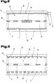
- hollow profile 1 made of plastic in cross section or in longitudinal section shown.
- This hollow profile 1 is produced and found in the extrusion process especially in construction for frames of windows, doors, partitions or the like. Use.
- the invention described below is also applicable to use hollow profiles for casements of windows, doors or the like.
- the one below Description is not based on the cross-sectional shapes shown in the drawings of the hollow profile 1 limited, but also for hollow profiles with U, T, Z-shaped or other cross-section valid.
- Outer walls 2 to 6 essentially form the outer outline of, for example, one L-shaped cross section having hollow profile 1.
- Essentially parallel and spaced longitudinal side walls 7, 8 form in use of the hollow profile 1 visible surfaces 9, 10.
- Approximately perpendicular to the long side walls 7, 8 connecting transverse side walls 11, 12 which are arranged at a distance from one another the longitudinal side walls 7, 8 and preferably have extensions 13, 14 for anchoring in masonry, in a plastic foam or the like.
- Longitudinal direction of the hollow profile 1 grooves 15 for receiving sealing profiles provided a seal between the frame and the sash to obtain.
- An interior 16 enclosed by the outer walls 2 to 6 is through Support webs 17, 18, 19 running parallel or at an angle to the outer walls 2 to 6 divided into several chambers 20, 21, 22.
- a reinforcement profile 23 is preferably located in a central chamber 21 Increasing the static values such as torsional rigidity, deflection resistance etc.
- This reinforcement profile 23 consists in particular of metallic Materials and can be rectangular, U-shaped, I-shaped or other Have cross sections.
- metallic reinforcement profiles 23 can be arranged on the inner surfaces of the central chamber 21 support cams 24 be, which protrude into the interior of the central chamber 21. These support cams 24 are designed such that the smallest possible contact area between the metallic reinforcement profile 23 and the walls of the central chamber 21. This creates a direct heat or cold transfer from the reinforcement profile 23 through to the surrounding support webs 17, 18, 19 or outer walls 2 to 6 Heat and cold conduction kept low.
- the reinforcement profile 23 made of carbon fibers or the like, having poor thermal conductivity and high strength Form materials, in which case the support cams 24 can also be omitted.
- the chambers bounded by the longitudinal side walls 7, 8 or assigned to them 20, 22 of the hollow profile 1 are spatially divided by a barrier film 25.
- This Barrier film 25 runs approximately parallel and at a distance 26 to the longitudinal side wall 7 and 8.
- the barrier film 25, the chambers 20 and 22 are thus in Sub-chambers 27, 28 extending in the longitudinal direction of the hollow profile 1 are divided.
- the barrier film 25 can approximately in the middle between the longitudinal side wall 7, 8 and the this adjacent and parallel support web 17 or the outer wall 4 is arranged be.
- the barrier film 25 can only one over two opposite walls extend single chamber 20 or 22 or over several, adjacent Chambers 20 and 22 may be continuous.
- the barrier film 25 is simultaneously with the extrusion process of the plastic body of the hollow profile 1 is introduced into the chambers 20, 22. It is preferred to a reel of barrier film 25 held in stock by a corresponding opening fed into the extruder nozzle, creating a positive connection between the plastic plastic material and the barrier film 25 is formed.
- the barrier film 25 extends only between two opposite support webs 18, 19 or between a support web 18 or 19 and a transverse side wall 11, 12 within a single chamber 20 or 22, the respective support webs 18, 19 or the transverse side walls 11, 12 are not completely separated by the barrier film 25, in order not to adversely affect the statics of the hollow profile 1.
- a complete one The support webs 18, 19 or the transverse side walls 11, 12 can be severed by different ones Measures can be prevented. So it is possible to have longitudinal side edges 29, 30 the barrier film 25 only over part of a wall thickness 31 of the support webs 18, 19 or to let the transverse side walls 11, 12 penetrate. A depth of penetration 32 of the long side edges 29, 30 is therefore smaller than the wall thickness 31 of the support webs 18, 19 or the transverse side walls 11, 12.
- the barrier film 25 extends continuously over several adjoining chambers 20, 22, are in the barrier film 25 in the contact areas of the crossing Support webs 18, 19 openings 34 arranged in the barrier film 25, which the flow allow the plastic plastic material.
- At least one surface facing the closest longitudinal side wall 7 or 8 35 of the barrier film 25 is designed to be reflective in order to strike a surface 35 To be able to reflect heat or cold radiation 36.
- the radiation reflective Surface 35 of the barrier film 25 can be reached in a variety of ways. So it is e.g. possible to form the barrier film 25 as a metal film 37, which has a high degree of reflection having. If necessary, this can also be done by polishing - at least on the surface 35 - be increased.
- the barrier film 25 thus increases the thermal resistance between the two long side walls 7, 8, often exposed to different temperatures all by reflecting the heat or cold radiation 36.
- the hollow profile 1 In a perpendicular to the visible surfaces 9, 10 heat transfer direction - according to a double arrow 38 - the hollow profile 1 accordingly has a lower heat transfer coefficient on.
- the division also contributes to reducing the k value of the hollow profile 1 of the chambers 20, 22 in several in the heat transfer direction - according to the double arrow 38 - successive subchambers 27, 28 at.
- barrier film 25 is also different from the illustrated embodiment possible to assign the barrier film 25 to only one of the long side walls 7 or 8.
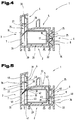
- Fig. 4 shows another way of forming the barrier film 25 for subdivision of the chambers 20, 22 in the longitudinal direction of the hollow profile 1, being for previous parts already mentioned the same reference numerals are used.
- the barrier film 25 with the reflective surface 35 has a reflector-like Shaping on.
- the barrier film 25 preferably has a bellows-like one or wavy cross-section.
- the barrier film designed in this way 25 incident heat or cold radiation 36 is thus reflected more effectively, since the heat or cold radiation 36 is reflected back to a higher percentage and is not redirected to surrounding parts or areas.
- the barrier film 25 is in this case in the plastic material of the support webs 17, 18, 19th or the outer walls 2 to 6 embedded that a complete separation of the same is avoided. This can in turn be dimensioned accordingly Penetration depth of the barrier film 25 in the plastic and through openings in the Barrier film 25 can be reached.
- FIG 5 shows another embodiment variant for the arrangement of the barrier film 25 in Hollow profile 1 shown, the same reference numerals for parts already described above be used.
- the barrier film 25 dividing the chambers 20, 22 is a multi-layer component educated.
- this consists of a base layer 39 and a reflection layer 40, each on the side facing the outer walls 2 to 6 the barrier film 25 is arranged.
- the reflection layer 40 can be non-positive with the base layer 39 connected metallic foil with a high degree of reflection be formed, or it is also possible to the reflective layer 40 by metal vapor deposition to form the base layer 39. It is also possible to use the reflection layer 40 to train as a chrome layer.
- the barrier films 25 are attached in the hollow profile 1 by angling the barrier film 25 in the region of the longitudinal side edges 29, 30 to fold 41, 42 and positive connection of the same with the respective support webs 17, 18, 19 or with an outer wall 2 to 6.
- the barrier film 25 is again in the chambers during the extrusion process 20, 22 to introduce that this runs parallel to the longitudinal side walls 7 and 8, respectively and the chambers 20 and 22 divided into the partial chambers 27, 28.
- the folds 41, 42 of the barrier film 25 are preferably in the plastic state of the extruded Profile slightly pressed against the respective inner surfaces of the chambers 20, 22.
- the contact surfaces of the folds 41, 42 can be free of the reflection layer 40 to be a high quality connection between the barrier film 25 and the To reach inner surfaces of the chambers 20, 22. Furthermore, this is advantageous a direct heat transfer between the reflection layer 40 and the plastic prevented.
- the reflection layer 40 increases the thermal resistance of the hollow profile 1 above all by the reflection of the heat or Cold radiation 36.
- a further increase in thermal resistance can be achieved by forming the base layer 39 as a heat insulation layer 43, because thus the heat transfer between the partial chambers 27, 28 of the chambers 20, 22 is further reduced by heat conduction.
- the thermal insulation layer 43 which also functions as a base layer 39, can be used by any materials known from the prior art with a low Thermal conductivity should be formed.
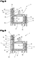
- FIG. 6 shows a further embodiment of the barrier film 25 in the chambers 20, 22 of the hollow profile 1, the same reference numerals for parts already described above be used.
- the chambers 20 assigned to the longitudinal side wall 7 are separated by a Barrier film 25, which is preferably on the surface facing the central chamber 21 is partially provided with surveys 44, divided. These surveys 44 are based on the wall parts of the hollow profile that run parallel to the longitudinal side wall 7 1 and thus ensure the maintenance of the distance 26 between the Longitudinal side wall 7 and the barrier film 25.
- the reflecting surface 35 of the barrier film 25 facing the longitudinal side wall 7 can in turn by the material of the barrier film 25 itself, by metal vapor deposition or painting of the barrier film 25 can be achieved.
- the chambers 22 delimited by the longitudinal side wall 8 are covered by the barrier film 25 divided into the partial chambers 27, 28 extending in the longitudinal direction of the hollow profile 1.
- This barrier film 25 representing a sandwich component 45 is replaced by one of the central chamber 21 facing thermal insulation layer 39, one of the long side wall 8 facing reflection layers 40 - preferably in the form of a metal foil 37 - and from a composite layer 46 connecting the base layer 39 and the metal foil 37 educated.
- the composite layer 46 only in some areas with the surfaces the reflection layer 40 and the heat insulation layer 43 connected. In particular, this can through a dotted, striped or lattice-shaped composite layer 46 can be achieved with the appropriate layer thickness.
- FIG. 7 shows another embodiment variant of the hollow profile 1 with a reduced heat transfer coefficient, the same for parts already mentioned above Reference numerals are used.
- the chambers 20, 22 adjacent to the outer walls 3, 6 are separated by partitions 47, 48 in channels 49, 50, 51 running in the direction of the length of the profile divided.
- the intermediate walls 47, 48 run parallel to the longitudinal side walls 7, 8 of the hollow profile 1, whereby the channels 49, 50, 51 in the heat transfer direction - According to double arrow 38 - between those arranged essentially parallel to each other Longitudinal side walls 7, 8 are arranged side by side or one behind the other.
- the intermediate wall 47 closest to the longitudinal side walls 7 and 8 has the reflection layer on the surface facing the longitudinal side wall 7 or 8 40 for total reflection of the radiation impinging on this reflection layer 40 in Form of cold or heat radiation 36.
- the reflection layer 40 on the intermediate wall 47 can in turn by a Metal vapor deposition, painting or by applying a film with a high degree of reflection can be achieved.
- the Appearance or the color of the hollow profile 1 is not changed.
- the overall visual impression the hollow profile 1 is thus also in a wrinkle or wave-forming
- the reflection layer 40 is not adversely changed.
- the application of the reflective layer 40 on the intermediate wall 47 compared to the application on a outer visible surface 9, 10 of the hollow profile 1 thus less accuracy.
- the amount of the reflection layer 40 is always only a fraction in terms of quantity the amount of plastic material, whereby the hollow profile 1 after removal of the reinforcing profile 23 can be fed to the recycling process without this negative changes in the properties of the recycled plastic material arise.
- partition walls 47, 48 or a plurality of partition walls are preferred during the extrusion process of the plastic profile.
- the channels 49, 50, 51 in Area of the longitudinal side walls 7, 8 by wall parts which can be inserted into the chambers 20, 22 To reach 52.
- These wall parts 52 consist of several, parallel to each other arranged partition walls 47, 48, the heights of which are essentially a height 53 corresponds to the chamber 20, 22 provided for subdivision.
- the partition walls 47, 48 are at least one extending transversely to the partition walls 47, 48 Connecting web 54 held in their parallel and spaced apart arrangement.
- a width of the connecting web 54 corresponds approximately to a width 55 of that Chamber in which the wall part 52 is to be introduced. With such a dimensioning of the wall part 52 this is in the respective chambers 20, 22 transverse to Longitudinal direction of the hollow profile 1 and a beating of the wall parts 52 to the Inner surfaces of the chambers 20, 22 are excluded.
- the wall parts 52 are preferably on the longitudinal side walls 7, 8 facing Provide surface areas with the reflection layer 40. It is also possible the surface of the connecting webs 54 and also that of the central chamber 20 facing surface areas of the intermediate walls 47, 48 with the reflection layer To train 40.
- connecting webs 54 of the wall parts 52 perpendicular to the To arrange transverse side walls 11, 12 offset direction, so a straight line Extension of a connecting web 54 over the entire width 55 of a chamber 20, 22 to avoid. Due to the overlap of the reflection layers 40 on the Intermediate walls 47, 48 thus create a complete shielding of the reinforcement profile 23 compared to the heat or cold radiation 36.
- the wall parts 52 are inserted into the chambers 20, 22 of the plastic profile preferably after the plastic profile has run out of the calibration or cooling devices, whereby the plastic profile with without additional processing steps the wall parts 52 can be provided and thus an inexpensive, industrial Series production of the plastic profile with thermal insulation is given.
- the moving in the wall parts 52 can also be parallel to the pulling-in process of the reinforcement profile 23 take place.
- the wall parts 52 are preferably extruded Bar material made of plastic or other low thermal conductivity having materials formed.
- the application of the reflection layer 40 on the Wall part 52 is preferably carried out before being introduced into the hollow profile 1 Evaporation with metal, painting or gluing of reflective foils.
- FIG 9 shows another embodiment variant of the hollow profile 1 with means for thermal insulation.
- the chambers 20, 22 adjacent to the longitudinal side walls 7, 8 are at least partially filled by a plastic foam body 56.
- the reflection layer 40 is arranged on the Longitudinal side wall 7 or 8 facing surface 35 of the plastic foam body 56.
- the reflection layer 40 is preferred through a metal foil 37, e.g. an aluminum foil is formed, which with the plastic foam body 56 is glued.
- the plastic foam body 56 with the metal foil 37 thus forms a compact, multilayer insulation body 57, which for Longitudinal side wall 7 or 8 to form a hollow chamber 58 between the reflection layer 40 and the outer walls 2 to 6 and the support webs 17 to 19 in the distance 26 to the respective longitudinal side wall 7 or 8 is arranged.
- That of the long side walls 7 or 8 spaced arrangement of the insulation body 57 can optionally by projecting from the inner surfaces of the chambers 20, 22 and substantially Brackets 59 extending parallel to the longitudinal side walls 7, 8 can be secured. These holders 59 are formed during the extrusion of the plastic profile.
- the insulation body 57 are preferred when leaving the cooling section for the Plastic profile inserted or drawn into the chambers 20, 22. With appropriate Dimensioning of the plastic foam body 56 can its elasticity be used to apply a prestressing force to the inner surfaces of the chambers 20 or 22 exercise. Thus, the position of the insulating body 57 is despite the existing hollow chamber 58 reliably met. In this case, the holder 59 can also be omitted.
- the insulation body 57 can be introduced with the aid of a broken line Tool 60 shown take place, which with the insulation body 57 during the pull-in process is in a positive connection.
- protrusions grip on the tool 60 into the plastic foam body 56 and through the push or tensile tool is also an insertion of the insulation body 57 in longer Plastic profiles possible.
- the insertion of the insulation body 57 can in turn take place simultaneously with the insertion of the reinforcement profile 23. After this The tool 60 and the plastic foam body can insert the insulation body 57 56 are disengaged and this through the hollow chamber 58 again be removed.
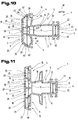
- the cross-sectionally different hollow profiles 1, according to FIGS. 10 to 13, can again from the different, mutually arranged outer walls 2 to 6 are formed, which essentially each have the outer contour of the hollow profile 1 establish.
- the longitudinal side walls 7, 8 form in the use position of the hollow profile 1 the visible surfaces 9, 10, again in turn approximately at right angles to the longitudinal side walls 7, 8 extending and also spaced transverse side walls 11, 12 are arranged, which the longitudinal side walls 7, 8 in their end regions connect.
- a wide variety of grooves 15 can in turn Recording of sealing profiles or other components may be provided.
- the single ones Outer walls 2 to 6 enclose the interior 16, which additionally by means of support webs 17 running parallel or at an angle to the outer walls 2 to 6 to 19 is divided into several chambers 20 to 22 separated from each other.
- the support cam 24 and other parts in one of the chambers, in particular in the Central chamber 21 is referred to the previous figures or reference taken.
- At least one is at least in the area of one of the visible surfaces 9, 10 Chamber 20, 22 arranged through the different outer walls 2 to 6 or the support webs 17 to 19 is bounded.
- These previously described outer walls 2 to 6 or the supporting webs 17 to 19 form 20 to 22 for each of the individual chambers these bounding surfaces 61, with at least two opposite one another these surfaces 61 each have at least two holding webs immediately adjacent to one another 62 are arranged thereon on the hollow profile 1 and the surfaces 61 are preferably in Exceed in the direction of the interior 16, the holding webs 62 preferably parallel to the longitudinal side walls 7, 8 forming the visible surface 9, 10 are aligned.
- This Projection of the holding webs 62 over the surfaces 61 can be between 0.5 mm and 10.0 mm be.
- a multiple arrangement is also preferred, in pairs arranged holding webs 62 in the individual chambers 20 to 22 possible and depends on the respective profile cross section or the thermal insulation value to be achieved or the k value (heat transfer value).
- the respectively opposite and mutually associated retaining webs 62 are included preferably arranged in planes aligned parallel to the longitudinal side walls 7, 8, which, however, are distant from these, but with the distances individual associated retaining webs 62 to other also related Retaining bars 62 can be different.
- the individual assigned to each other and opposite retaining webs 62 can at least over part of one Dimension 63 of individual chambers 20, 22 in parallel to the longitudinal side walls 7, 8 Location extend, but it is also possible that this over the full Dimension 63 of the chambers 20, 22 extend.
- the barrier film 25 is in the individual chambers 20, 22 in a parallel position to the Longitudinal side walls 7, 8 or in a preferably rectangular position to the heat transfer direction - Aligned according to the double arrow 38 - and from the long side walls 7, 8 spaced apart in the distance 26.
- the distance 26 starting from the longitudinal side walls 7, 8 in each of the individual in the chambers 20, 22 arranged barrier films 25 may be chosen the same. But it is also possible how 11, the distance 26 between the barrier film 25 and the longitudinal side wall 7, 8 to differently form each other in different chambers. This is due to the choice of the profile cross section and the arrangement of the individual Chambers 20, 22 are interdependent and can of course be freely selected.
- the barrier film 25 can be, for example, a film made of plastic, in particular be made of polyester, PVC (polyvinyl chloride), etc., one surface 35 of the barrier film 25 of the longitudinal side wall 7 or 8 and one facing away from it Surface 64 of the central chamber 21 faces. But it is independent of it possible, the barrier film 25 from a foil made of metal, in particular gold and / or Silver and / or bronze and / or platinum and / or chrome and / or aluminum or the like. to build. Of course, a combination or a multi-layer or multilayer barrier film 25 made of the aforementioned film materials possible.
- the immediately adjacent Retaining webs 62 each the surfaces 35, 64 of the barrier film 25 starting from whose longitudinal side edges 29, 30 overlap at least in regions.
- the immediately arranged in the area of one of the longitudinal side edges 29, 30 and assigned to one another Retaining webs 62 have the holding surfaces facing the surfaces 35, 64 of the barrier film 25 65, 66, which abut the surfaces 35, 64 of the barrier film 25.
- these holding surfaces 65, 66 of the holding webs 62 at least in some areas connected to the surfaces 35, 64 of the barrier film 25 and / or molded onto it are.
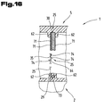
- FIG. 12 shows that at least one of the surfaces 35, 64 of the barrier film 25 is covered by a holding web 62.
- the holding webs 62 is the barrier film 25 in the area of both surfaces 35, 64 covered by these, with a connection in regions between the barrier film 25 and the plastic material of the hollow profile 1 is possible.
- the barrier film 25 By arranging at least one barrier film 25 in one of the chambers 20, 22, the subdivision of the same into the one described in FIG Longitudinal direction of the hollow profile 1 and in the heat transfer direction - according Double arrow 38 - partial chambers arranged one behind the other or next to one another 27, 28. But it is also essential that the barrier film 25 at the same time as the Extrusion process of the plastic body for the hollow profile 1 in the respective chambers 20, 22 introduced and connected to the plastic material at least in some areas will, as has already been described previously.
- 14 and 15 is a portion of a chamber 20 on an enlarged scale shown, which can be seen here that a width 68 of the barrier film 25 between the spaced apart longitudinal side edges 29, 30 approximately in the inner dimension 63 corresponds to the respective chamber 20.
- the long edges run 29, 30 approximately in alignment with the inner surfaces 61 of FIG respective chamber 20.
- the barrier film 25 between each directly assigned to each other Holding webs 62 arranged or on the one facing the other Holding surfaces 65, 66 is held or molded.
- crossbars 70 will during the extrusion process and formation or shaping of the individual holding webs 62 formed by the plasticized plastic material, whereby in the area the spaced apart longitudinal side edges 29, 30 additionally a positive connection through the protruding through the openings 69 Crosspieces 70 is achieved. But it would also be possible regardless of the Barrier film 25 at least in the area of one of its longitudinal side edges 29, 30 or in Coverage area with the holding webs 62 with an adhesion-promoting layer, such as e.g. a primer layer or the like. To ensure good adhesion of the plastic material to reach the barrier film 25.
- this layer 71 for example one of the surfaces 35, 64 is vapor-deposited and / or the surface 35, 64 is vapor-deposited as well optionally laminated onto the barrier film 25 and / or coated with it can be.
- This layer 71 can, for example, by a metal layer, in particular made of gold and / or silver and / or bronze and / or platinum and / or chrome and / or Aluminum be formed.
- the barrier film 25 preferably has a crosswise direction to its longitudinal extent a thickness 72 between 0.05 mm and 10.0 mm, preferably between 0.075 mm and 1.0 mm, so that the barrier film 25 has a certain inherent rigidity or one certain resistance to deformation at the same time as the extrusion process has accompanying insertion process or molding process.
- FIGS. 1 to 15 are used for the same parts will.
- the barrier film 25 or the layers forming this and / or the layer 71 is included designed to be heat-resistant and / or weather-resistant and / or UV-resistant, because this ensures a long service life and therefore a good thermal insulation value can.
- the barrier film 25 and possibly the layer 71 should be reflective, in particular heat rays should be designed reflective, as a result of which Barrier film 25 and / or the layer 71 is formed as a heat-insulating layer or layer is.
- the barrier film 25 and optionally the layer 71 can be multilayered or formed in several layers from the materials previously described be, as is shown in simplified form in the region of the longitudinal side edge 30.
- the reflection layer mentioned in the figures described above can also be used 40, e.g. also made of gold and / or silver and / or bronze and / or platinum and / or chrome and / or aluminum etc. may be formed, as previously for the barrier film 25 or layer 71 has been described.
- the barrier film 25 at least in the area of one of them Longitudinal edges 29, 30 - in the present embodiment only in the area of Longitudinal edge 29 shown - a bend 73 and / or a bead and / or one Envelope and / or have a fold, for the sake of simplicity a multiple Bend 73 has been shown schematically.
- At least one of the surfaces can be used to increase the inherent rigidity of the barrier film 25 35, 64 of the barrier film 25 deformed, in particular with impressions 74 of the most varied Be provided, as this is also simplified schematically has been shown in the central region between the longitudinal side edges 29, 30.
Landscapes
- Engineering & Computer Science (AREA)
- Civil Engineering (AREA)
- Structural Engineering (AREA)
- Refrigerator Housings (AREA)
- Laminated Bodies (AREA)
- Building Environments (AREA)
- Special Wing (AREA)
Abstract
Description
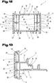
- Fig. 1
- ein mit einer Sperrfolie erfindungsgemäß ausgebildetes Hohlprofil, im Querschnitt und beispielhafter, vereinfachter Darstellung;
- Fig. 2
- einen Teilbereich des Hohlprofils, geschnitten, gemäß den Linien II - II in Fig. 1;
- Fig. 3
- eine andere Ausführung der Sperrfolie im erfindungsgemäßen Hohlprofil;
- Fig. 4
- eine andere Ausführungsform der Sperrfolie im beispielhaft dargestellten, erfindungsgemäßen Hohlprofil;
- Fig. 5
- eine weitere Möglichkeit der Anbringung der Sperrfolie im erfindungsgemäßen Hohlprofil;
- Fig. 6
- weitere Ausbildungsvarianten der Sperrfolie im erfindungsgemäßen Hohlprofil;
- Fig. 7
- eine weitere Möglichkeit der Anbringung der Sperrfolie im erfindungsgemäßen Hohlprofil;
- Fig. 8
- eine weitere Ausführungsvariante zur Anbringung der Sperrfolie im erfindungsgemäßen Hohlprofil;
- Fig. 9
- eine andere Ausführungsvariante eines wärmegedämmten, erfindungsgemäßen Hohlprofils;
- Fig. 10
- eine weitere Halterungsmöglichkeit der Sperrfolie im erfindungsgemäßen Hohlprofil;
- Fig. 11
- eine weitere Möglichkeit der Anbringung der Sperrfolie in einem erfindungsgemäßen Hohlprofil;
- Fig. 12
- eine weitere mögliche Halterung der Sperrfolie im erfindungsgemäßen Hohlprofil;
- Fig. 13
- eine weitere Halterungsmöglichkeit der Sperrfolie im erfindungsgemäßen Hohlprofil;
- Fig. 14
- einen Teilbereich einer Kammer eines erfindungsgemäßen Hohlprofils mit einer darin angeordneten Sperrfolie, in vergrößerter Darstellung;
- Fig. 15
- die Sperrfolie mit dem Hohlprofil nach Fig. 14, in Seitenansicht, geschnitten, gemäß den Linien XV - XV in Fig. 14;
- Fig. 16
- eine weitere und gegebenenfalls für sich eigenständige Ausbildung sowie Halterungsmöglichkeit der Sperrfolie in einem erfindungsgemäßen Hohlprofil, in Stirnansicht, geschnitten.
- 1
- Hohlprofil
- 2
- Außenwand
- 3
- Außenwand
- 4
- Außenwand
- 5
- Außenwand
- 6
- Außenwand
- 7
- Längsseitenwand
- 8
- Längsseitenwand
- 9
- Sichtfläche
- 10
- Sichtfläche
- 11
- Querseitenwand
- 12
- Querseitenwand
- 13
- Fortsatz
- 14
- Fortsatz
- 15
- Nut
- 16
- Innenraum
- 17
- Stützsteg
- 18
- Stützsteg
- 19
- Stützsteg
- 20
- Kammer
- 21
- Kammer
- 22
- Kammer
- 23
- Verstärkungsprofil
- 24
- Abstütznocke
- 25
- Sperrfolie
- 26
- Distanz
- 27
- Teilkammer
- 28
- Teilkammer
- 29
- Längsseitenkante
- 30
- Längsseitenkante
- 31
- Wandstärke
- 32
- Eindringtiefe
- 33
- Fortsatz
- 34
- Durchbruch
- 35
- Oberfläche
- 36
- Wärme- bzw. Kältestrahlung
- 37
- Metallfolie
- 38
- Doppelpfeil
- 39
- Tragschichte
- 40
- Reflexionsschichte
- 41
- Falz
- 42
- Falz
- 43
- Wärmedämmschichte
- 44
- Erhebung
- 45
- Sandwichbauteil
- 46
- Verbundschichte
- 47
- Zwischenwand
- 48
- Zwischenwand
- 49
- Kanal
- 50
- Kanal
- 51
- Kanal
- 52
- Wandteil
- 53
- Höhe
- 54
- Verbindungssteg
- 55
- Breite
- 56
- Kunststoffschaumkörper
- 57
- Isolationskörper
- 58
- Hohlkammer
- 59
- Halter
- 60
- Werkzeug
- 61
- Fläche
- 62
- Haltesteg
- 63
- Abmessung
- 64
- Oberfläche
- 65
- Haltefläche
- 66
- Haltefläche
- 67
- Durchbruch
- 68
- Breite
- 69
- Durchbruch
- 70
- Quersteg
- 71
- Schichte
- 72
- Stärke
- 73
- Abkantung
- 74
- Einprägung
Claims (64)
- Hohlprofil aus Kunststoff mit Mitteln zur Wärmeisolation, insbesondere für Fenster, Türen und Rahmen, mit Außenwänden, welche durch in etwa parallel verlaufende Längsseitenwände und in etwa rechtwinkelig dazu verlaufenden Querseitenwände gebildet sind, und einem durch Stützstege in Kammern unterteilten Innenraum, dadurch gekennzeichnet, daß im Innenraum (16) oder in zumindest einer einer Längsseitenwand (7, 8) zugeordneten Kammer (20, 22) eine in einer Distanz (26) zur Längsseitenwand (7, 8) und parallel zu dieser verlaufende Sperrfolie (25) angeordnet ist.
- Hohlprofil nach Anspruch 1, dadurch gekennzeichnet, daß die Sperrfolie (25) die Kammer (20, 22) in eine der Längsseitenwand (7, 8) zugeordnete erste Teilkammer (27) und in eine zwischen der Sperrfolie (25) und einem Stützsteg (17) oder einer Außenwand (4) angeordnete zweite Teilkammer (28) unterteilt.
- Hohlprofil nach Anspruch 1 oder 2, dadurch gekennzeichnet, daß die Sperrfolie (25) in etwa im Mittel zwischen der Längsseitenwand (7, 8) und dem zu dieser benachbarten und parallel verlaufenden Stützsteg (17) oder Außenwand (4) angeordnet ist.
- Hohlprofil nach einem oder mehreren der vorhergehenden Ansprüche, dadurch gekennzeichnet, daß die Sperrfolie (25) im Bereich zwischen zwei in etwa parallel verlaufenden, die Kammer (20, 22) bildenden Stützstegen (18, 19) bzw. einem Stützsteg (18, 19) und der beabstandeten Außenwand (2, 4, 5) angeordnet ist.
- Hohlprofil nach einem oder mehreren der vorhergehenden Ansprüche, dadurch gekennzeichnet, daß mehreren Kammern (20, 22) jeweils zumindest eine Sperrfolie (25) zugeordnet ist.
- Hohlprofil nach einem oder mehreren der vorhergehenden Ansprüche, dadurch gekennzeichnet, daß die Sperrfolien (25) zueinander in einer unterschiedlichen Distanz (26) zur Längsseitenwand (7, 8) angeordnet sind.
- Hohlprofil nach einem oder mehreren der vorhergehenden Ansprüche, dadurch gekennzeichnet, daß die Sperrfolie (25) durch eine Folie aus Kunststoff, insbesondere aus Polyester, PVC (Polyvinylchlorid) gebildet ist.
- Hohlprofil nach einem oder mehreren der Ansprüche 1 bis 6, dadurch gekennzeichnet, daß die Sperrfolie (25) durch eine Folie aus Metall, insbesondere aus Gold und/oder Silber und/oder Bronze und/oder Platin und/oder Chrom und/oder Aluminium gebildet ist.
- Hohlprofil nach einem oder mehreren der vorhergehenden Ansprüche, dadurch gekennzeichnet, daß zumindest auf eine der Oberflächen (35, 64) der Sperrfolie (25) eine Schichte (71) aufgebracht, insbesondere mit dieser beschichtet und/oder kaschiert und/oder bedampft ist.
- Hohlprofil nach einem oder mehreren der vorhergehenden Ansprüche, dadurch gekennzeichnet, daß die Schichte (71) durch eine Metallschichte, insbesondere aus Gold und/oder Silber und/oder Bronze und/oder Platin und/oder Chrom und/oder Aluminium gebildet ist.
- Hohlprofil nach einem oder mehreren der vorhergehenden Ansprüche, dadurch gekennzeichnet, daß die Sperrfolie (25) quer zu ihrer Längserstreckung eine Stärke (72) zwischen 0,05 mm und 10,0 mm, bevorzugt zwischen 0,075 mm und 1,0 mm, aufweist.
- Hohlprofil nach einem oder mehreren der vorhergehenden Ansprüche, dadurch gekennzeichnet, daß die Sperrfolie (25) und/oder die Schichte (71) wärmebeständig und/oder bewitterungsbeständig und/oder UV-beständig ausgebildet ist.
- Hohlprofil nach einem oder mehreren der vorhergehenden Ansprüche, dadurch gekennzeichnet, daß zumindest eine der nächstliegenden Längsseitenwand (7, 8) zugewandte Oberfläche (35) der Sperrfolie (25) reflektierend, insbesondere Wärmestrahlen reflektierend ausgebildet ist.
- Hohlprofil nach einem oder mehreren der vorhergehenden Ansprüche, dadurch gekennzeichnet, daß die Sperrfolie (25) reflektierend, insbesondere Wärmestrahlen reflektierend ausgebildet ist.
- Hohlprofil nach einem oder mehreren der vorhergehenden Ansprüche, dadurch gekennzeichnet, daß die Schichte (71) reflektierend, insbesondere Wärmestrahlen reflektierend ausgebildet ist.
- Hohlprofil nach einem oder mehreren der vorhergehenden Ansprüche, dadurch gekennzeichnet, daß die Sperrfolie (25) und/oder die Schichte (71) als wärmedämmende Schichte bzw. Lage ausgebildet ist.
- Hohlprofil nach einem oder mehreren der vorhergehenden Ansprüche, dadurch gekennzeichnet, daß die Sperrfolie (25) mehrschichtig bzw. mehrlagig ausgebildet ist.
- Hohlprofil nach einem oder mehreren der vorhergehenden Ansprüche, dadurch gekennzeichnet, daß die Sperrfolie (25) aus einer mit einer Reflexionsschichte (40) versehenen Wärmedämmschichte (43) gebildet ist.
- Hohlprofil nach einem oder mehreren der vorhergehenden Ansprüche, dadurch gekennzeichnet, daß die Reflexionsschichte (40) über eine Verbundschichte (46) mit der Wärmedämmschichte (43) verbunden ist.
- Hohlprofil nach einem oder mehreren der vorhergehenden Ansprüche, dadurch gekennzeichnet, daß die Verbundschichte (46) bereichsweise mit den Oberflächen der Reflexionsschichte (40) und der Wärmedämmschichte (43) verbunden ist.
- Hohlprofil nach einem oder mehreren der vorhergehenden Ansprüche, dadurch gekennzeichnet, daß die Verbundschichte (46) mit Durchbrüchen versehen und z.B. durch Streifen, ein Netz oder ein Gitter gebildet ist.
- Hohlprofil nach einem oder mehreren der vorhergehenden Ansprüche, dadurch gekennzeichnet, daß die Reflexionsschichte (40) auf der der Außenwand (3, 6) zugewandten Seite der Sperrfolie (25) angeordnet ist.
- Hohlprofil nach einem oder mehreren der vorhergehenden Ansprüche, dadurch gekennzeichnet, daß die Sperrfolie (25) zumindest im Bereich ihrer Längsseitenkanten (29, 30) mit einer Haftvermittlungsschichte versehen ist.
- Hohlprofil nach einem oder mehreren der vorhergehenden Ansprüche, dadurch gekennzeichnet, daß die Sperrfolie (25) zumindest im Bereich einer ihrer Längsseitenkanten (29, 30) eine Abkantung (73) und/oder ein Sicke und/oder einen Umschlag und/oder einen Falz aufweist.
- Hohlprofil nach einem oder mehreren der vorhergehenden Ansprüche, dadurch gekennzeichnet, daß die die Kammer (20, 22) unterteilende Sperrfolie (25) an ihren Längsseitenkanten (29, 30) mit den Stützstegen (18, 19) und/oder Außenwänden (2, 5) thermisch verbunden ist.
- Hohlprofil nach einem oder mehreren der vorhergehenden Ansprüche, dadurch gekennzeichnet, daß die Längsseitenkanten (29, 30) der Sperrfolie (25) im Kunststoff eingebettet sind.
- Hohlprofil nach einem oder mehreren der vorhergehenden Ansprüche, dadurch gekennzeichnet, daß die Längsseitenkanten (29, 30) der Sperrfolie (25) formschlüssig mit dem Kunststoff des Hohlprofils (1), insbesondere mit den Außenwänden (2 bis 6), Stützstegen (17 bis 19), Haltestegen (62) verbunden ist.
- Hohlprofil nach einem oder mehreren der vorhergehenden Ansprüche, dadurch gekennzeichnet, daß der Kunststoff des Hohlprofils (1) gleichzeitig mit dem Extrusionsvorgang an die Sperrfolie (25) angeformt ist.
- Hohlprofil nach einem oder mehreren der vorhergehenden Ansprüche, dadurch gekennzeichnet, daß die Sperrfolie (25) im Bereich ihrer Längsseitenkanten (29, 30) abgewinkelte Falze (41, 42) aufweist und diese mit den Stützstegen (18, 19) bzw. einem Stützsteg (18, 19) und der beabstandeten Außenwand (2, 5) verbunden oder in diese eingebettet sind.
- Hohlprofil nach einem oder mehreren der vorhergehenden Ansprüche, dadurch gekennzeichnet, daß Fortsätze (33) an den Längsseitenkanten (29, 30) der Sperrfolie (25) zueinander in Längsrichtung der Sperrfolie (25) beabstandet angeordnet sind und diese die Außenwände (2, 5) bzw. die Stützstege (18, 19) zumindest teilweise durchragen.
- Hohlprofil nach einem oder mehreren der vorhergehenden Ansprüche, dadurch gekennzeichnet, daß im Bereich der Längsseitenkanten (29, 30) der Sperrfolie (25) diese durchsetzende und in Längsrichtung derselben zueinander distanzierte Durchbrüche (69) angeordnet sind.
- Hohlprofil nach einem oder mehreren der vorhergehenden Ansprüche, dadurch gekennzeichnet, daß zumindest die Reflexionsschichte (40) bzw. die gesamte Sperrfolie (25) einen zacken- oder wellenförmigen Querschnitt aufweist.
- Hohlprofil nach einem oder mehreren der vorhergehenden Ansprüche, dadurch gekennzeichnet, daß zumindest eine der Oberflächen (35, 64) der Sperrfolie (25) verformt, insbesondere mit Einprägungen (74) versehen ist.
- Hohlprofil nach einem oder mehreren der vorhergehenden Ansprüche, dadurch gekennzeichnet, daß eine Breite (68) der Sperrfolie (25) in zur Längsseitenwand (7, 8) paralleler Lage zumindest in etwa einer Abmessung (63) der Kammer (20, 22) in der gleichen Richtung entspricht.
- Hohlprofil nach einem oder mehreren der vorhergehenden Ansprüche, dadurch gekennzeichnet, daß in zumindest einer Kammer (20, 22) des Hohlprofils (1) an zumindest zwei einander gegenüberliegenden, diese umgrenzenden Flächen (61) jeweils zumindest zwei einander unmittelbar benachbarte Haltestege (62) an diesen am Hohlprofil (1) angeordnet sind, welche parallel zu den eine Sichtfläche (9, 10) bildenden Längsseitenwänden (7, 8) ausgerichtet sind.
- Hohlprofil nach einem oder mehreren der vorhergehenden Ansprüche, dadurch gekennzeichnet, daß sich die einander gegenüberliegenden Haltestege (62) zumindest über einen Teil der Abmessung (63) der Kammer (20, 22) in zur Längsseitenwand (7, 8) paralleler Lage erstrecken.
- Hohlprofil nach einem oder mehreren der vorhergehenden Ansprüche, dadurch gekennzeichnet, daß die unmittelbar benachbarten Haltestege (62) jeweils die Oberflächen (35, 64) der Sperrfolie (25) ausgehend von den Längsseitenkanten (29, 30) derselben zumindest bereichsweise übergreifen.
- Hohlprofil nach einem oder mehreren der vorhergehenden Ansprüche, dadurch gekennzeichnet, daß einander zugewandte Halteflächen (65, 66) der Haltestege (62) an den Oberflächen (35, 64) der Sperrfolie (25) anliegen.
- Hohlprofil nach einem oder mehreren der vorhergehenden Ansprüche, dadurch gekennzeichnet, daß die Halteflächen (65, 66) der Haltestege (62) zumindest bereichsweise mit den Oberflächen (35, 64) der Sperrfolie (25) verbunden und/oder an diese angeformt sind.
- Hohlprofil nach einem oder mehreren der vorhergehenden Ansprüche, dadurch gekennzeichnet, daß zwischen jeweils einander zugewandten Halteflächen (65, 66) der Haltestege (62) diese verbindende Querstege (70) angeordnet sind, welche die Durchbrüche (69) in der Sperrfolie (25) durchsetzen.
- Hohlprofil nach einem oder mehreren der vorhergehenden Ansprüche, dadurch gekennzeichnet, daß die Sperrfolie (25) zumindest im Bereich einer der Oberflächen (35, 64) von den Haltestegen (62) abgedeckt ist.
- Hohlprofil nach einem oder mehreren der vorhergehenden Ansprüche, dadurch gekennzeichnet, daß eine Eindringtiefe (32) einer Längsseitenkante (29, 30) kleiner ist als eine Wandstärke (31) der Stützstege (18, 19) bzw. der Außenwände (2, 5).
- Hohlprofil nach einem oder mehreren der vorhergehenden Ansprüche, dadurch gekennzeichnet, daß die Sperrfolie (25) über mehrere, aneinander grenzende Kammern (20, 22) durchgehend angeordnet ist.
- Hohlprofil nach einem oder mehreren der vorhergehenden Ansprüche, dadurch gekennzeichnet, daß die Sperrfolie (25) im Bereich mit kreuzenden Stützstegen (18, 19) Durchbrüche (34) aufweist.
- Hohlprofil aus Kunststoff mit Mitteln zur Wärmeisolation, insbesondere für Fenster, Türen und Rahmen, mit Außenwänden, welche durch in etwa parallel verlaufende Längsseitenwände und in etwa rechtwinkelig dazu verlaufenden Querseitenwände gebildet sind, und einem durch Stützstege in Kammern unterteilten Innenraum, insbesondere nach einem oder mehreren der vorhergehenden Ansprüche, dadurch gekennzeichnet, daß zumindest eine der Kammern (20, 21, 22), bevorzugt die an die Außenwand (3, 6) angrenzende Kammer (20, 22), durch Zwischenwände (47, 48) ausbildende Wandteile (52) in in Richtung der Länge des Hohlprofils (1) verlaufende Kanäle (49, 50, 51) unterteilt ist.
- Hohlprofil nach Anspruch 45, dadurch gekennzeichnet, daß die Zwischenwände (47, 48) mehrschichtig ausgebildet sind, wobei eine der Schichten eine Reflexionsschichte (40) ist.
- Hohlprofil nach Anspruch 45 oder 46, dadurch gekennzeichnet, daß die Reflexionsschichte (40) zumindest auf einer der nächstliegenden Längsseitenwand (7, 8) zugeordneten Seite zumindest einer Zwischenwand (47, 48) angeordnet ist.
- Hohlprofil nach einem oder mehreren der Ansprüche 45 bis 47, dadurch gekennzeichnet, daß die Kanäle (49, 50, 51) in einer senkrecht zur Längsseitenwand (7, 8) verlaufenden Richtung nebeneinander angeordnet sind.
- Hohlprofil nach einem oder mehreren der Ansprüche 45 bis 48, dadurch gekennzeichnet, daß eine Zwischenwand (47, 48) mit zumindest einer Längsseitenwand (7, 8) und/oder einer Querseitenwand (11, 12) und/oder einem Stützsteg (17, 18, 19) einer Kammer (20, 22) verbunden, z.B. angeformt oder angeklebt, ist.
- Hohlprofil nach einem oder mehreren der Ansprüche 45 bis 49, dadurch gekennzeichnet, daß die Wandteile (52) als Einschubteile für die Kammer (20, 22) ausgebildet sind.
- Hohlprofil nach einem oder mehreren der Ansprüche 45 bis 50, dadurch gekennzeichnet, daß zwischen einer Längsseitenwand (7, 8) und einem Stützsteg (17) mehrere Zwischenwände (47, 48) angeordnet sind.
- Hohlprofil nach einem oder mehreren der Ansprüche 45 bis 51, dadurch gekennzeichnet, daß die in etwa senkrecht zur Längsseitenwand (7, 8) bzw. zum Stützsteg (17) ausgerichteten Verbindungsstege (54) zwischen der Längsseitenwand (7, 8), dem Stützsteg (17) und den Zwischenwänden (47, 48) in in etwa senkrecht zur Querseitenwand (11, 12) verlaufender Richtung versetzt sind.
- Hohlprofil nach einem oder mehreren der Ansprüche 45 bis 52, dadurch gekennzeichnet, daß die Reflexionsschichte (40) auf mehreren Zwischenwänden (47, 48) bevorzugt auf den der nächstliegenden Längsseitenwand (7, 8) zugewandten Oberflächen (35) angeordnet ist.
- Hohlprofil nach einem oder mehreren der Ansprüche 45 bis 53, dadurch gekennzeichnet, daß die Reflexionsschichten (40) auf einander benachbarten Zwischenwänden (47, 48) sich in senkrecht zu den Querseitenwänden (11, 12) verlaufender Richtung überlappen.
- Hohlprofil nach einem oder mehreren der Ansprüche 45 bis 54, dadurch gekennzeichnet, daß auf den Verbindungsstegen (54) eine Reflexionsschichte (40) angeordnet ist.
- Hohlprofil nach einem oder mehreren der Ansprüche 45 bis 55, dadurch gekennzeichnet, daß auf der einen Kanal (49, 50, 51) begrenzenden Zwischenwand (47, 48) und den einander zugewandten Oberflächen der diesen begrenzenden Verbindungsstegen (54) eine Reflexionsschichte (40) angeordnet ist.
- Hohlprofil aus Kunststoff mit Mitteln zur Wärmeisolation, insbesondere für Fenster, Türen und Rahmen, mit Außenwänden, welche durch in etwa parallel verlaufende Längsseitenwände und in etwa rechtwinkelig dazu verlaufenden Querseitenwände gebildet sind, und einem durch Stützstege in Kammern unterteilten Innenraum, insbesondere nach einem oder mehreren der vorhergehenden Ansprüche, dadurch gekennzeichnet, daß in den Innenraum (16) bzw. zumindest in einer einer Längsseitenwand (7, 8) zugeordneten Kammer (20, 22) ein Isolationskörper (57), bestehend aus einem Kunststoffschaumkörper (56) und zumindest einer Reflexionsschichte (40) eingesetzt ist.
- Hohlprofil nach Anspruch 57, dadurch gekennzeichnet, daß der Isolationskörper (57) zumindest auf der der nächstliegenden Längsseitenwand (7, 8) zugeordneten Oberfläche (35) mit der Reflexionsschichte (40) versehen ist.
- Hohlprofil nach Anspruch 57 oder 58, dadurch gekennzeichnet, daß zwischen dem Isolationskörper (57) und der Längsseitenwand (7, 8) eine Hohlkammer (58) gebildet ist.
- Hohlprofil nach einem oder mehreren der Ansprüche 57 bis 59, dadurch gekennzeichnet, daß die Hohlkammer (58) zwischen dem Isolationskörper (57) und einem Stützsteg (17) gebildet ist.
- Hohlprofil nach einem oder mehreren der Ansprüche 57 bis 60, dadurch gekennzeichnet, daß der Isolationskörper (57) über eine gegen die Innenflächen der Kammern (20, 22) gerichtete Vorspannkraft an diesen anliegt.
- Hohlprofil nach einem oder mehreren der Ansprüche 57 bis 61, dadurch gekennzeichnet, daß in die Kammern (20, 22) ragende Halter (59) für die Halterung des Isolationskörpers (57) am Hohlprofil (1) angeordnet sind.
- Hohlprofil nach einem oder mehreren der vorhergehenden Ansprüche, dadurch gekennzeichnet, daß die Reflexionsschichte (40) durch eine Metalldampfschichte, eine Lackschichte oder eine Folie gebildet ist.
- Hohlprofil nach einem oder mehreren der vorhergehenden Ansprüche, dadurch gekennzeichnet, daß die Reflexionsschichte (40) aus einem Metall, z.B. Aluminium, Chrom oder dgl., besteht.
Applications Claiming Priority (6)
| Application Number | Priority Date | Filing Date | Title |
|---|---|---|---|
| AT1588/96 | 1996-09-06 | ||
| AT158896 | 1996-09-06 | ||
| AT158896A AT404860B (de) | 1996-09-06 | 1996-09-06 | Hohlprofil aus kunststoff mit mitteln zur wärmeisolation |
| AT106397 | 1997-06-18 | ||
| AT106397A AT406784B (de) | 1997-06-18 | 1997-06-18 | Hohlprofil aus kunststoff mit mitteln zur wärmeisolation |
| AT1063/97 | 1997-06-18 |
Publications (3)
| Publication Number | Publication Date |
|---|---|
| EP0828052A2 true EP0828052A2 (de) | 1998-03-11 |
| EP0828052A3 EP0828052A3 (de) | 1999-12-22 |
| EP0828052B1 EP0828052B1 (de) | 2003-11-19 |
Family
ID=25594764
Family Applications (1)
| Application Number | Title | Priority Date | Filing Date |
|---|---|---|---|
| EP97115430A Expired - Lifetime EP0828052B1 (de) | 1996-09-06 | 1997-09-06 | Hohlprofil, insbesondere aus Kunststoff mit Wärmeisolationsmittel |
Country Status (7)
| Country | Link |
|---|---|
| EP (1) | EP0828052B1 (de) |
| BG (1) | BG101869A (de) |
| CZ (1) | CZ281197A3 (de) |
| DE (1) | DE59711021D1 (de) |
| HU (1) | HUP9701458A3 (de) |
| PL (1) | PL321951A1 (de) |
| SK (1) | SK119597A3 (de) |
Cited By (13)
| Publication number | Priority date | Publication date | Assignee | Title |
|---|---|---|---|---|
| DE19829460A1 (de) * | 1998-04-28 | 1999-11-11 | Sendenhorst Kunststoffroehren | Profil für Fenster oder Türen |
| RU2157444C1 (ru) * | 2000-05-24 | 2000-10-10 | Закрытое акционерное общество "Проплекс" | Комплект профилей для сборки оконных блоков |
| WO2001006079A1 (de) * | 1999-07-15 | 2001-01-25 | SCHÜCO International KG | Kunststoffhohlprofil |
| EP0953711A3 (de) * | 1998-04-28 | 2001-04-04 | Kunststoffröhren Sendenhorst GmbH | Verfahren zum Herstellen eines Profils für Fenster oder Türen |
| RU2171347C1 (ru) * | 2000-08-04 | 2001-07-27 | Гусев Валерий Александрович | Пластмассовый профиль для сборки блоков для закрытия оконных и/или дверных проемов |
| DE10014186A1 (de) * | 2000-03-23 | 2001-09-27 | Huels Troisdorf | Hohlkammerprofil |
| GB2413145A (en) * | 2004-04-17 | 2005-10-19 | Sapa Building Systems Ltd | Glazing frames |
| DE102008008343A1 (de) * | 2008-02-08 | 2009-08-13 | Aluplast Gmbh | Profil für Fenster- oder Türrahmen |
| GB2467950A (en) * | 2009-02-21 | 2010-08-25 | Synseal Extrusions Ltd | Method of manufacturing a window profile |
| EP2607599A1 (de) * | 2011-12-23 | 2013-06-26 | REHAU AG + Co | Hohlprofil für einen Rahmen |
| DE102012009838A1 (de) * | 2012-05-16 | 2013-11-21 | Technoform Bautec Holding Gmbh | Isoliersteg mit Folienisolierkörper |
| WO2019179912A1 (de) * | 2018-03-21 | 2019-09-26 | Rehau Ag + Co | Hohlkammerprofil für ein fenster oder eine tür sowie dieses umfassende rahmenbaugruppe |
| EP3825502A1 (de) * | 2019-11-26 | 2021-05-26 | REHAU AG + Co | Hohlkammerprofil für ein fenster oder eine tür sowie dieses umfassende rahmenbaugruppe |
Families Citing this family (1)
| Publication number | Priority date | Publication date | Assignee | Title |
|---|---|---|---|---|
| DE202021106856U1 (de) | 2021-12-16 | 2023-03-28 | REHAU Industries SE & Co. KG | Hohlkammerprofil für ein Fenster oder eine Tür sowie dieses umfassende Rahmenbaugruppe |
Family Cites Families (10)
| Publication number | Priority date | Publication date | Assignee | Title |
|---|---|---|---|---|
| AT372491B (de) * | 1980-07-10 | 1983-10-10 | Vmw Ranshofen Berndorf Ag | Verbundprofil |
| DE3407639A1 (de) * | 1984-03-01 | 1985-09-12 | Gebrüder Kömmerling Kunststoffwerke GmbH, 6780 Pirmasens | Verbundstab, insbesondere fuer fensterrahmen, tuerrahmen und rollaeden |
| CH686897A5 (de) * | 1993-11-01 | 1996-07-31 | Schweizer Ag E | Verbundprofil. |
| DE9411396U1 (de) * | 1994-07-14 | 1994-09-15 | Wicona Bausysteme Gmbh, 89077 Ulm | Wärmegedämmtes Verbundprofil |
| DE4426331A1 (de) * | 1994-07-25 | 1996-02-08 | Veka Ag | Extrudiertes Kunststoffprofil für Fenster, Türen o. dgl. |
| DE9413790U1 (de) * | 1994-08-26 | 1995-12-21 | Correcta GmbH, 34537 Bad Wildungen | Hohlprofil-Fensterrahmen |
| DE9420251U1 (de) * | 1994-12-17 | 1995-02-09 | Zenker-Fenster GmbH & Co. KG, 37671 Höxter | Fenster, Tür, Festverglasung o.dgl. |
| DE29512502U1 (de) * | 1995-02-01 | 1995-09-21 | Krämer, Albert, 65554 Limburg | Isolierkern für Verbundprofil, insbesondere für Fenster, Türen und Fassadenkonstruktionen |
| DE19632048C2 (de) * | 1996-08-09 | 2000-10-19 | Hubert Distner | Fensterprofil |
| DE29715346U1 (de) * | 1996-09-03 | 1997-12-11 | KBE Kunststoffproduktion GmbH, 12277 Berlin | Wärmegedämmtes Hohlprofil insbesondere aus thermoplastischem Kunststoff für Fenster oder Türen |
-
1997
- 1997-09-01 HU HU9701458A patent/HUP9701458A3/hu unknown
- 1997-09-01 BG BG101869A patent/BG101869A/xx unknown
- 1997-09-04 SK SK1195-97A patent/SK119597A3/sk unknown
- 1997-09-05 PL PL97321951A patent/PL321951A1/xx unknown
- 1997-09-05 CZ CZ972811A patent/CZ281197A3/cs unknown
- 1997-09-06 DE DE59711021T patent/DE59711021D1/de not_active Expired - Lifetime
- 1997-09-06 EP EP97115430A patent/EP0828052B1/de not_active Expired - Lifetime
Cited By (17)
| Publication number | Priority date | Publication date | Assignee | Title |
|---|---|---|---|---|
| DE19829460A1 (de) * | 1998-04-28 | 1999-11-11 | Sendenhorst Kunststoffroehren | Profil für Fenster oder Türen |
| EP0953711A3 (de) * | 1998-04-28 | 2001-04-04 | Kunststoffröhren Sendenhorst GmbH | Verfahren zum Herstellen eines Profils für Fenster oder Türen |
| US6478916B1 (en) | 1998-04-28 | 2002-11-12 | Funke Kunstsoffe Gmbh | Method for the manufacture of a section for windows or doors |
| WO2001006079A1 (de) * | 1999-07-15 | 2001-01-25 | SCHÜCO International KG | Kunststoffhohlprofil |
| US6920726B2 (en) | 1999-07-15 | 2005-07-26 | SCHÜCO International KG | Hollow plastic section |
| DE10014186A1 (de) * | 2000-03-23 | 2001-09-27 | Huels Troisdorf | Hohlkammerprofil |
| RU2157444C1 (ru) * | 2000-05-24 | 2000-10-10 | Закрытое акционерное общество "Проплекс" | Комплект профилей для сборки оконных блоков |
| RU2171347C1 (ru) * | 2000-08-04 | 2001-07-27 | Гусев Валерий Александрович | Пластмассовый профиль для сборки блоков для закрытия оконных и/или дверных проемов |
| GB2413145A (en) * | 2004-04-17 | 2005-10-19 | Sapa Building Systems Ltd | Glazing frames |
| GB2413145B (en) * | 2004-04-17 | 2007-02-28 | Sapa Building Systems Ltd | Glazing frames |
| DE102008008343A1 (de) * | 2008-02-08 | 2009-08-13 | Aluplast Gmbh | Profil für Fenster- oder Türrahmen |
| GB2467950A (en) * | 2009-02-21 | 2010-08-25 | Synseal Extrusions Ltd | Method of manufacturing a window profile |
| EP2607599A1 (de) * | 2011-12-23 | 2013-06-26 | REHAU AG + Co | Hohlprofil für einen Rahmen |
| DE102012009838A1 (de) * | 2012-05-16 | 2013-11-21 | Technoform Bautec Holding Gmbh | Isoliersteg mit Folienisolierkörper |
| WO2013170952A1 (de) | 2012-05-16 | 2013-11-21 | Technoform Bautec Holding Gmbh | Isoliersteg mit folienisolierkörper |
| WO2019179912A1 (de) * | 2018-03-21 | 2019-09-26 | Rehau Ag + Co | Hohlkammerprofil für ein fenster oder eine tür sowie dieses umfassende rahmenbaugruppe |
| EP3825502A1 (de) * | 2019-11-26 | 2021-05-26 | REHAU AG + Co | Hohlkammerprofil für ein fenster oder eine tür sowie dieses umfassende rahmenbaugruppe |
Also Published As
| Publication number | Publication date |
|---|---|
| EP0828052B1 (de) | 2003-11-19 |
| BG101869A (en) | 1998-10-30 |
| CZ281197A3 (cs) | 1998-03-18 |
| DE59711021D1 (de) | 2003-12-24 |
| EP0828052A3 (de) | 1999-12-22 |
| SK119597A3 (en) | 1998-12-02 |
| HUP9701458A2 (hu) | 1998-03-30 |
| HU9701458D0 (en) | 1997-10-28 |
| PL321951A1 (en) | 1998-03-16 |
| HUP9701458A3 (en) | 1998-10-28 |
Similar Documents
| Publication | Publication Date | Title |
|---|---|---|
| EP1055046B2 (de) | Abstandhalterprofil für isolierscheibeneinheit | |
| EP1017923B1 (de) | Abstandhalterprofil für isolierscheibeneinheit | |
| EP2106491B2 (de) | Kunststoffprofil für fenster-, türen- und fassadenelemente | |
| EP0828052B1 (de) | Hohlprofil, insbesondere aus Kunststoff mit Wärmeisolationsmittel | |
| DE3407639A1 (de) | Verbundstab, insbesondere fuer fensterrahmen, tuerrahmen und rollaeden | |
| EP0957226A1 (de) | Verbundprofil für Rahmen von Fenstern, Türe, Fassadenelementen und dergl., IR-Reflexionsfolie insbes. für dieses Verbundprofil und Verwendung der IR-Reflexionsfolie bei dem Verbundprofil | |
| EP0370376A2 (de) | Torblatt | |
| EP2864567B1 (de) | Isoliersteg für ein verbundprofil für fenster-, türen- oder fassadenelemente und verfahren zum herstellen eines solchen isolierstegs und verbundprofil mit einem solchen isoliersteg | |
| DE202014010902U1 (de) | Isolierelement für Fassaden- oder Lichtdachkonstruktionen | |
| DE2800811A1 (de) | Kastenfoermige bautafel aus extrudiertem lichtdurchlaessigem kunststoff | |
| DE8202323U1 (de) | Waermegedaemmter rahmen fuer fenster, tueren, fassadenkonstruktionen u. dergleichen | |
| EP1099038B1 (de) | Abstandhalterprofil für einen abstandhalterrahmen einer isolierscheibeneinheit | |
| EP1127990A2 (de) | Rahmenkonstruktion mit verbesserter Wärmedämmung | |
| DE102010056128A1 (de) | Abstandhalter für Isolierglaseinheiten und Verfahren zu dessen Herstellung | |
| DE202021106856U1 (de) | Hohlkammerprofil für ein Fenster oder eine Tür sowie dieses umfassende Rahmenbaugruppe | |
| DE19707624C2 (de) | Dämmprofil für Befestigungsprofile für Fassadenplatten | |
| EP0550841B1 (de) | Fassadenkonstruktion | |
| AT406784B (de) | Hohlprofil aus kunststoff mit mitteln zur wärmeisolation | |
| EP0780525B1 (de) | Fassadenprofilkonstruktion | |
| DE2824396A1 (de) | Aus wenigstens zwei unterschiedlichen werkstoffen zusammengesetztes abdichtprofil | |
| AT404860B (de) | Hohlprofil aus kunststoff mit mitteln zur wärmeisolation | |
| EP0940518A1 (de) | Verkleidungselement zum Verkleiden von Gebäudewänden | |
| EP3626900B1 (de) | Dämmelement für eine fassaden-, fenster- oder türkonstruktion und fassadenkonstruktion mit einem derartigen dämmelement | |
| DE19632048C2 (de) | Fensterprofil | |
| DE10251431A1 (de) | Haustür |
Legal Events
| Date | Code | Title | Description |
|---|---|---|---|
| PUAI | Public reference made under article 153(3) epc to a published international application that has entered the european phase |
Free format text: ORIGINAL CODE: 0009012 |
|
| AK | Designated contracting states |
Kind code of ref document: A2 Designated state(s): BE CH DE DK FR GB IE IT LI LU NL PT SE |
|
| AX | Request for extension of the european patent |
Free format text: AL;LT;LV;RO;SI |
|
| RIN1 | Information on inventor provided before grant (corrected) |
Inventor name: NIMMRICHTER, FRANZ, ING. |
|
| PUAL | Search report despatched |
Free format text: ORIGINAL CODE: 0009013 |
|
| AK | Designated contracting states |
Kind code of ref document: A3 Designated state(s): AT BE CH DE DK ES FI FR GB GR IE IT LI LU MC NL PT SE |
|
| AX | Request for extension of the european patent |
Free format text: AL;LT;LV;RO;SI |
|
| RAP1 | Party data changed (applicant data changed or rights of an application transferred) |
Owner name: ALUPLAST AUSTRIA GMBH |
|
| 17P | Request for examination filed |
Effective date: 20000621 |
|
| AKX | Designation fees paid |
Free format text: BE CH DE DK FR GB IE IT LI LU NL PT SE |
|
| AXX | Extension fees paid |
Free format text: AL PAYMENT 20000621;LT PAYMENT 20000621;LV PAYMENT 20000621;RO PAYMENT 20000621;SI PAYMENT 20000621 |
|
| 17Q | First examination report despatched |
Effective date: 20020716 |
|
| GRAH | Despatch of communication of intention to grant a patent |
Free format text: ORIGINAL CODE: EPIDOS IGRA |
|
| GRAS | Grant fee paid |
Free format text: ORIGINAL CODE: EPIDOSNIGR3 |
|
| GRAA | (expected) grant |
Free format text: ORIGINAL CODE: 0009210 |
|
| AK | Designated contracting states |
Kind code of ref document: B1 Designated state(s): BE CH DE DK FR GB IE IT LI LU NL PT SE |
|
| AX | Request for extension of the european patent |
Extension state: AL LT LV RO SI |
|
| PG25 | Lapsed in a contracting state [announced via postgrant information from national office to epo] |
Ref country code: NL Free format text: LAPSE BECAUSE OF FAILURE TO SUBMIT A TRANSLATION OF THE DESCRIPTION OR TO PAY THE FEE WITHIN THE PRESCRIBED TIME-LIMIT Effective date: 20031119 |
|
| REG | Reference to a national code |
Ref country code: GB Ref legal event code: FG4D Free format text: NOT ENGLISH |
|
| REG | Reference to a national code |
Ref country code: CH Ref legal event code: EP |
|
| REF | Corresponds to: |
Ref document number: 59711021 Country of ref document: DE Date of ref document: 20031224 Kind code of ref document: P |
|
| REG | Reference to a national code |
Ref country code: IE Ref legal event code: FG4D Free format text: GERMAN |
|
| REG | Reference to a national code |
Ref country code: CH Ref legal event code: NV Representative=s name: ABP PATENT NETWORK SWISS GMBH |
|
| PG25 | Lapsed in a contracting state [announced via postgrant information from national office to epo] |
Ref country code: SE Free format text: LAPSE BECAUSE OF FAILURE TO SUBMIT A TRANSLATION OF THE DESCRIPTION OR TO PAY THE FEE WITHIN THE PRESCRIBED TIME-LIMIT Effective date: 20040219 Ref country code: DK Free format text: LAPSE BECAUSE OF FAILURE TO SUBMIT A TRANSLATION OF THE DESCRIPTION OR TO PAY THE FEE WITHIN THE PRESCRIBED TIME-LIMIT Effective date: 20040219 |
|
| GBT | Gb: translation of ep patent filed (gb section 77(6)(a)/1977) |
Effective date: 20040218 |
|
| LTIE | Lt: invalidation of european patent or patent extension |
Effective date: 20031119 |
|
| NLV1 | Nl: lapsed or annulled due to failure to fulfill the requirements of art. 29p and 29m of the patents act | ||
| ET | Fr: translation filed | ||
| PLBE | No opposition filed within time limit |
Free format text: ORIGINAL CODE: 0009261 |
|
| STAA | Information on the status of an ep patent application or granted ep patent |
Free format text: STATUS: NO OPPOSITION FILED WITHIN TIME LIMIT |
|
| 26N | No opposition filed |
Effective date: 20040820 |
|
| REG | Reference to a national code |
Ref country code: CH Ref legal event code: PFA Owner name: ALUPLAST AUSTRIA GMBH Free format text: ALUPLAST AUSTRIA GMBH#ROSSLAUF 26#4552 WARTBERG/KREMS (AT) -TRANSFER TO- ALUPLAST AUSTRIA GMBH#ROSSLAUF 26#4552 WARTBERG/KREMS (AT) |
|
| PGFP | Annual fee paid to national office [announced via postgrant information from national office to epo] |
Ref country code: IE Payment date: 20070913 Year of fee payment: 11 |
|
| PGFP | Annual fee paid to national office [announced via postgrant information from national office to epo] |
Ref country code: LU Payment date: 20070919 Year of fee payment: 11 |
|
| PG25 | Lapsed in a contracting state [announced via postgrant information from national office to epo] |
Ref country code: PT Free format text: LAPSE BECAUSE OF NON-PAYMENT OF DUE FEES Effective date: 20040419 |
|
| PGFP | Annual fee paid to national office [announced via postgrant information from national office to epo] |
Ref country code: CH Payment date: 20080930 Year of fee payment: 12 |
|
| PGFP | Annual fee paid to national office [announced via postgrant information from national office to epo] |
Ref country code: FR Payment date: 20080915 Year of fee payment: 12 |
|
| PGFP | Annual fee paid to national office [announced via postgrant information from national office to epo] |
Ref country code: GB Payment date: 20080827 Year of fee payment: 12 |
|
| PGFP | Annual fee paid to national office [announced via postgrant information from national office to epo] |
Ref country code: BE Payment date: 20080731 Year of fee payment: 12 |
|
| PGFP | Annual fee paid to national office [announced via postgrant information from national office to epo] |
Ref country code: IT Payment date: 20080927 Year of fee payment: 12 |
|
| REG | Reference to a national code |
Ref country code: IE Ref legal event code: MM4A |
|
| PG25 | Lapsed in a contracting state [announced via postgrant information from national office to epo] |
Ref country code: IE Free format text: LAPSE BECAUSE OF NON-PAYMENT OF DUE FEES Effective date: 20080908 |
|
| BERE | Be: lapsed |
Owner name: *ALUPLAST AUSTRIA G.M.B.H. Effective date: 20090930 |
|
| REG | Reference to a national code |
Ref country code: CH Ref legal event code: PL |
|
| GBPC | Gb: european patent ceased through non-payment of renewal fee |
Effective date: 20090906 |
|
| REG | Reference to a national code |
Ref country code: FR Ref legal event code: ST Effective date: 20100531 |
|
| PG25 | Lapsed in a contracting state [announced via postgrant information from national office to epo] |
Ref country code: LU Free format text: LAPSE BECAUSE OF NON-PAYMENT OF DUE FEES Effective date: 20080906 |
|
| PG25 | Lapsed in a contracting state [announced via postgrant information from national office to epo] |
Ref country code: FR Free format text: LAPSE BECAUSE OF NON-PAYMENT OF DUE FEES Effective date: 20090930 |
|
| PG25 | Lapsed in a contracting state [announced via postgrant information from national office to epo] |
Ref country code: BE Free format text: LAPSE BECAUSE OF NON-PAYMENT OF DUE FEES Effective date: 20090930 |
|
| PG25 | Lapsed in a contracting state [announced via postgrant information from national office to epo] |
Ref country code: LI Free format text: LAPSE BECAUSE OF NON-PAYMENT OF DUE FEES Effective date: 20090930 Ref country code: CH Free format text: LAPSE BECAUSE OF NON-PAYMENT OF DUE FEES Effective date: 20090930 |
|
| PG25 | Lapsed in a contracting state [announced via postgrant information from national office to epo] |
Ref country code: GB Free format text: LAPSE BECAUSE OF NON-PAYMENT OF DUE FEES Effective date: 20090906 |
|
| PG25 | Lapsed in a contracting state [announced via postgrant information from national office to epo] |
Ref country code: IT Free format text: LAPSE BECAUSE OF NON-PAYMENT OF DUE FEES Effective date: 20090906 |
|
| PGFP | Annual fee paid to national office [announced via postgrant information from national office to epo] |
Ref country code: DE Payment date: 20120928 Year of fee payment: 16 |
|
| REG | Reference to a national code |
Ref country code: DE Ref legal event code: R119 Ref document number: 59711021 Country of ref document: DE Effective date: 20140401 |
|
| PG25 | Lapsed in a contracting state [announced via postgrant information from national office to epo] |
Ref country code: DE Free format text: LAPSE BECAUSE OF NON-PAYMENT OF DUE FEES Effective date: 20140401 |