EP0828075A1 - Brennstoffeinspritzventil mit Niederschlagreduzierung - Google Patents
Brennstoffeinspritzventil mit Niederschlagreduzierung Download PDFInfo
- Publication number
- EP0828075A1 EP0828075A1 EP97115623A EP97115623A EP0828075A1 EP 0828075 A1 EP0828075 A1 EP 0828075A1 EP 97115623 A EP97115623 A EP 97115623A EP 97115623 A EP97115623 A EP 97115623A EP 0828075 A1 EP0828075 A1 EP 0828075A1
- Authority
- EP
- European Patent Office
- Prior art keywords
- nozzle
- heat
- injection valve
- nozzle body
- temperature
- Prior art date
- Legal status (The legal status is an assumption and is not a legal conclusion. Google has not performed a legal analysis and makes no representation as to the accuracy of the status listed.)
- Withdrawn
Links
- 238000002347 injection Methods 0.000 title claims abstract description 122
- 239000007924 injection Substances 0.000 title claims abstract description 122
- 239000000446 fuel Substances 0.000 title claims abstract description 120
- 230000009467 reduction Effects 0.000 title claims abstract description 80
- 238000002485 combustion reaction Methods 0.000 claims abstract description 70
- 238000004821 distillation Methods 0.000 claims abstract description 24
- 238000009413 insulation Methods 0.000 claims description 42
- 239000000463 material Substances 0.000 claims description 18
- 230000001737 promoting effect Effects 0.000 claims description 13
- 230000015572 biosynthetic process Effects 0.000 claims description 10
- RYGMFSIKBFXOCR-UHFFFAOYSA-N Copper Chemical compound [Cu] RYGMFSIKBFXOCR-UHFFFAOYSA-N 0.000 description 40
- 229910052802 copper Inorganic materials 0.000 description 40
- 239000010949 copper Substances 0.000 description 40
- 238000009825 accumulation Methods 0.000 description 19
- 230000000694 effects Effects 0.000 description 18
- 238000012360 testing method Methods 0.000 description 14
- 238000010420 art technique Methods 0.000 description 13
- 239000004071 soot Substances 0.000 description 13
- 239000000126 substance Substances 0.000 description 11
- 230000005855 radiation Effects 0.000 description 9
- 238000003780 insertion Methods 0.000 description 8
- 230000037431 insertion Effects 0.000 description 8
- 239000002243 precursor Substances 0.000 description 7
- 238000010586 diagram Methods 0.000 description 5
- 239000000567 combustion gas Substances 0.000 description 4
- 238000001816 cooling Methods 0.000 description 4
- 230000007423 decrease Effects 0.000 description 4
- 239000007791 liquid phase Substances 0.000 description 4
- 238000000034 method Methods 0.000 description 4
- 239000000498 cooling water Substances 0.000 description 3
- 238000012856 packing Methods 0.000 description 3
- 230000001105 regulatory effect Effects 0.000 description 3
- 239000012809 cooling fluid Substances 0.000 description 2
- 230000003247 decreasing effect Effects 0.000 description 2
- 230000001419 dependent effect Effects 0.000 description 2
- 239000007789 gas Substances 0.000 description 2
- 238000007792 addition Methods 0.000 description 1
- 230000004323 axial length Effects 0.000 description 1
- 238000003763 carbonization Methods 0.000 description 1
- 230000001276 controlling effect Effects 0.000 description 1
- 230000002542 deteriorative effect Effects 0.000 description 1
- 238000001704 evaporation Methods 0.000 description 1
- 230000008020 evaporation Effects 0.000 description 1
- 239000012774 insulation material Substances 0.000 description 1
- 230000001788 irregular Effects 0.000 description 1
- 238000004519 manufacturing process Methods 0.000 description 1
- 238000005259 measurement Methods 0.000 description 1
- 230000007246 mechanism Effects 0.000 description 1
- 239000002184 metal Substances 0.000 description 1
- 229910052751 metal Inorganic materials 0.000 description 1
- 238000012986 modification Methods 0.000 description 1
- 230000004048 modification Effects 0.000 description 1
- 230000003647 oxidation Effects 0.000 description 1
- 238000007254 oxidation reaction Methods 0.000 description 1
- 230000008569 process Effects 0.000 description 1
- 239000007921 spray Substances 0.000 description 1
- 230000001629 suppression Effects 0.000 description 1
Images






Classifications
-
- F—MECHANICAL ENGINEERING; LIGHTING; HEATING; WEAPONS; BLASTING
- F02—COMBUSTION ENGINES; HOT-GAS OR COMBUSTION-PRODUCT ENGINE PLANTS
- F02M—SUPPLYING COMBUSTION ENGINES IN GENERAL WITH COMBUSTIBLE MIXTURES OR CONSTITUENTS THEREOF
- F02M61/00—Fuel-injectors not provided for in groups F02M39/00 - F02M57/00 or F02M67/00
- F02M61/14—Arrangements of injectors with respect to engines; Mounting of injectors
-
- F—MECHANICAL ENGINEERING; LIGHTING; HEATING; WEAPONS; BLASTING
- F02—COMBUSTION ENGINES; HOT-GAS OR COMBUSTION-PRODUCT ENGINE PLANTS
- F02M—SUPPLYING COMBUSTION ENGINES IN GENERAL WITH COMBUSTIBLE MIXTURES OR CONSTITUENTS THEREOF
- F02M53/00—Fuel-injection apparatus characterised by having heating, cooling or thermally-insulating means
- F02M53/04—Injectors with heating, cooling, or thermally-insulating means
-
- F—MECHANICAL ENGINEERING; LIGHTING; HEATING; WEAPONS; BLASTING
- F02—COMBUSTION ENGINES; HOT-GAS OR COMBUSTION-PRODUCT ENGINE PLANTS
- F02B—INTERNAL-COMBUSTION PISTON ENGINES; COMBUSTION ENGINES IN GENERAL
- F02B3/00—Engines characterised by air compression and subsequent fuel addition
- F02B3/06—Engines characterised by air compression and subsequent fuel addition with compression ignition
-
- F—MECHANICAL ENGINEERING; LIGHTING; HEATING; WEAPONS; BLASTING
- F02—COMBUSTION ENGINES; HOT-GAS OR COMBUSTION-PRODUCT ENGINE PLANTS
- F02D—CONTROLLING COMBUSTION ENGINES
- F02D2200/00—Input parameters for engine control
- F02D2200/02—Input parameters for engine control the parameters being related to the engine
- F02D2200/06—Fuel or fuel supply system parameters
- F02D2200/0606—Fuel temperature
Definitions
- the present invention relates to a deposit reduction fuel injection valve comprising nozzle body which has a nozzle hole formed so as to face a combustion chamber of an internal combustion engine and which directly injects and supplies fuel to the combustion chamber, wherein temperature adjusting means for adjusting the temperature of a nozzle having the nozzle hole formed thereon adjusts the temperature of the tip portion of the nozzle body so as to maintain the temperature equal to or lower than a 90%-distillation temperature of fuel, thereby suppressing the generation and accumulation of deposits on the internal surface of the nozzle hole and hence resulting in reduced variations in a flow rate.
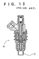
- Examples of a first prior art technique are an electromagnetic fuel injection valve (Japanese Patent Application Laid-open (kokai) No. 62-103456) shown in FIG. 13 and a fuel injection valve (Japanese Patent Application Laid-open (kokai) No. 63-151970) shown in FIG. 14. Both of these inventions are intended to improve the heat radiation characteristics of the tip end of the injection valve N so as to reduce the temperature of the tip end of the fuel injection valve by providing the tip end of the injection valve N with a shroud S having a high heat conductivity.
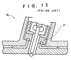
- FIG. 15 Japanese Utility Model Publication (kokoku) No. 8-5336. This structure is intended to cool a nozzle N by placing in the vicinity of the nozzle N a packing P capable of circulating a cooling fluid.
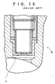
- An example of a third prior art technique is a heat radiation member of a fuel injection nozzle of an internal-combustion engine shown in FIG. 16 (Japanese Patent Publication (kokoku) No. 63-65823).
- This heat radiation member is intended to improve the heat radiation characteristics of the tip end of the nozzle N by providing an elastically deformable seal lip L at the tip end of a bush.
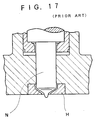
- An example of fourth prior art technique is a cylinder head for use in a diesel engine shown in FIG. 17 (Japanese Patent Publication (kokoku) No. 59-1103 ).
- This invention is intended to provide an engine head H which shields a nozzle from heat.
- This illustrative fourth example is directed toward improving the durability and reliability of an injection valve of a direct-injection high supercharging diesel engine, as well as to a technique for accomplishing the foregoing objects (1) through (3).
- the examples of the first prior art technique are directed toward providing the tip end of the injection valve N with the shroud S having a high heat conductivity.
- the flow of heat within the injection valve N fitted to the engine has not been elucidated.
- the invention is intended to reduce the temperature of the injection valve N by providing the injection valve N with the shroud S having a high heat conductivity, the location of the engine to which the injection valve N is fitted is not specified, so that a heat flow path is not defined. Consequently, the improvements or advantageous effects of the invention cannot be specified.
- the packing P capable of circulating a cooling fluid is placed in the vicinity of the nozzle N.
- the packing P is located away from the tip end of the nozzle N, therefore resulting in a small effect of reducing the temperature of the tip end of the nozzle N. Since forming a cooling path up to the vicinity of the injection valve involves difficulties in terms of manufacture of an engine head, it is difficult to say that the invention has a high degree of practicality.
- the thermal insulation characteristics of the tip end of the nozzle N is improved by providing the elastic deformable seal lip L at the tip end of the bush.
- the seal lip L is a simple heat insulation member and consequently has a high degree of practicality. Since the material of the seal lip L is limited to elastic metal, the heat conductivity of the heat insulation member is equal to or greater than that of the nozzle. Although the heat insulation member has a function of facilitating flow of heat, it is hard to say that the function is sufficient. The heat insulation member does not have such a heat insulating effect as to interrupt or partially suppress the flow of heat.
- the example of the third prior art technique also fails to provide a sufficient function of facilitating flow of heat from the nozzle N to the engine head.
- the most important matter to reduce the temperature of the nozzle through use of a member having a high heat conductivity is to reduce the heat resistance between the nozzle and the engine head to as low a value.
- the member is press-fitted onto the nozzle, so that the contact resistance of the heat flow path is reduced.
- there are clearances between the nozzles and the engine head, or the nozzles and the engine head are only in slight contact with each other. Since there are no active efforts for reducing the heat resistance of other areas, the temperature of the tip end of the nozzle therefore cannot be reduced effectively with such an arrangement.
- the side surface of the nozzle has a wide area, it is very important to improve the heat radiation characteristics of the nozzle by reducing the contact resistance of the side surface of the nozzle.
- the engine head H shields the nozzle N from heat.
- it is not intended to prevent the flow rate of fuel from decreasing as a result of accumulation of deposits on the internal surface of the nozzle hole of the injection valve.
- a protuberance formed at the tip end of the nozzle is exposed to the combustion chamber through a thermal insulation plate.
- the embodiment section of the patent describing the fourth example does not include any descriptions related to the position of the nozzle hole.
- the nozzle hole is formed in the protuberance at the front end of the nozzle, due to the function of the nozzle hole.
- the temperature of the tip end becomes higher than a 90%-distillation temperature of fuel. Therefore, deposits are accumulated on the internal surface of the nozzle hole, thereby resulting in a reduction in the flow rate of the injection valve.
- An objection of the present invention is to solve the problem of a reduction in the flow rate of the injection valve as previously described. More specifically, the present invention is directed toward a deposit reduction fuel injection valve comprising a fuel injection valve which has a nozzle hole formed so as to face a combustion chamber of an internal combustion engine and which directly injects and supplies fuel to the combustion chamber, wherein there is prevented a phenomenon of a flow rate of fuel being reduced by a decrease in the area of the nozzle hole as a result of accumulation of deposits on the internal surface of the nozzle hole, by a reduction in lowering the temperature of the tip portion of the nozzle body so as to be lower than the 90%-distillation temperature of fuel to be used.
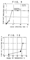
- FIG. 9 shows the manner in which the flow rate of the injection valve decreases at that time. The flow rate abruptly decreases until ten hours elapse from the commencement of the test. Although there is no further reduction in the flow rate after lapse of 10 hr., the rate of reduction of the flow rate reaches 10% when the test is completed.
- deposits are acknowledged to have been accumulated as a result of carbonization. From the result of this observation, it is understood that deposits cause a reduction in the area of the nozzle hole and a reduction in the flow rate of the injection valve.
- the inventors examined the manner in which the flow rate of the injection valve was reduced by performing an engine test similar to that illustrated in FIG. 9 for 30 hr. on condition that the temperature of the tip portion of the nozzle body was decreased so as to be maintained lower than 165°C. The results of such an engine test are illustrated in FIG. 10. On condition that the temperature of the tip portion of the nozzle body is 155°C, the rate of reduction in the flow rate is about 3%. In contrast, on condition that the temperature of the tip portion of the nozzle body is reduced to 100°C, the rate of reduction in the flow rate becomes about 1%.
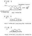
- FIG. 3 schematically illustrates the occurrence of the phenomenon.
- Fuel contains precursors of deposit which will serve as the nucleus of deposits during the course of generation of the deposits. At room temperature, these precursors of deposit are dispersed in the fuel.
- the fuel After having been injected, the fuel remains in trace amounts on the internal surface of the nozzle hole. If the temperature of the tip portion of the nozzle body is lower than the 90%-distillation temperature of the fuel (150°C), the fuel remaining on the internal surface of the nozzle hole is held in a liquid phase. Accordingly, the precursors of deposit contained in the fuel also remain dispersed in the fuel. The precursors of deposit remaining in the dispersed state are easily flushed away together with the fuel by the next injection, thereby suppressing the generation of deposits on the internal surface of the nozzle hole.
- the temperature of the tip portion of the nozzle body is higher than the 90%-distillation temperature (150°C)
- evaporation of the fuel remaining inside the nozzle hole is promoted. Therefore, the precursors of deposit cannot remain in the dispersed state in the fuel, so they aggregate on the internal wall surface of the nozzle hole. In such a state, it is difficult to flush the thus-aggregated precursors of deposit away at the time of the next injection, so they remain in the nozzle hole. As a result, the accumulation of deposits proceeds.
- the inventors of the present invention have learned that, in order to suppress the generation of deposits on the internal surface of the nozzle hole, it is necessary to reduce the temperature of the tip portion of the nozzle body so as to maintain the temperature lower than a 90%-distillation temperature of the fuel, to constantly hold the fuel remaining on the internal surface of the nozzle hole in a liquid phase, thereby maintaining precursors of deposit dispersed in the fuel.
- the heat flow path is formed by inserting a substance having a high heat conductivity between the side surface of the nozzle and the engine head so as to minimize the contact resistance between the side surface and the substance and between the substance and the engine head.
- the heat resistance between the side surface of the nozzle body and the engine head is reduced, and the heat supplied to the nozzle body as a result of convection or radiation of a combustion gas is easily dissipated to the engine head.
- the inventors of the present invention also learned important factors in suppressing the reduction in the flow rate of the injection valve by having performed another test from different viewpoints.
- the temperature history of the tip portion of the nozzle body was measured under the same conditions as those shown in FIG. 9. Further, the injection valve was removed from the engine head after lapse of 3, 7, 15, and 30 hours, and the thickness of soot built up on the surface of the nozzle body was determined. The result of such determination is shown in FIG. 11.
- the temperature of the tip portion of the nozzle body which is 180°C immediately after the commencement of the engine test, drops to 165°C after the lapse of 30 min. since the commencement of the test.
- the temperature of the tip portion of the nozzle body decreases with the lapse of time, and the temperature drops to about 130°C after the lapse of 15 hr.
- the thickness of the soot built up on the surface of the nozzle body increases with the lapse of time, and the thickness reaches 0.34 mm after the lapse of 15 hr.
- a phenomenon is observed in which the temperature of the tip portion of the nozzle body sharply increases immediately before the operating time of the engine reaches 30 hr.
- soot has been scraped off from the surface of the nozzle body, so that the metallic base material of the nozzle body is exposed. From the results of this test, it is understood that the reduction in the temperature of the tip portion of the nozzle body has strong relevancy to the soot accumulated on the surface of the nozzle body. In short, it is concluded that the soot forms a thermal insulation layer which suppresses the flow of heat supplied to the nozzle body from the combustion chamber.
- the soot serves as a heat insulation layer which reduces the temperature of the nozzle body. Therefore, it is understood that the soot suppresses the progress of the reduction of the flow rate of the injection valve.
- It is a still further object of the present invention to provide a deposit reduction fuel injection valve comprising a nozzle hole, formed on a tip portion of a nozzle body so as to face a combustion chamber of an internal combustion engine, for injecting directly fuel in the combustion chamber, and a temperature adjusting means for adjusting a temperature of the tip portion of the nozzle body having the nozzle hole so as to maintain the temperature equal to or lower than a 90%-distillation temperature of fuel.
- the heat flow formation means comprises a heat conduction promoting member which is formed from a material having a high heat conductivity and is interposed between an internal wall surface of the engine head and an outer side surface of the nozzle body, and the heat conduction promoting member reduces a heat resistance between the nozzle body and the engine head, so that the dissipation of the heat flow supplied to the nozzle body toward the engine head is promoted.
- a deposit reduction fuel injection valve of the present invention is directed toward a fuel injection valve comprises a nozzle body which has a nozzle hole formed thereon so as to face a combustion chamber of an internal combustion engine and which directly injects and supplies fuel to the combustion chamber.
- a heat flow path is formed by inserting a substance having a high heat conductivity between the side surface of the nozzle body and the engine head so as to minimize the contact resistance between the side surface and the substance and between the substance and the engine head.
- the heat resistance between the nozzle body and the engine head is reduced, and the heat supplied to the nozzle body as a result of convection or radiation of a combustion gas becomes easily dissipated to the engine head.
- An area of the nozzle body exposed in the combustion chamber or part of this area of the nozzle body is covered with a substance having a low heat conductivity so as to interrupt or suppress the inflow of heat supplied to the nozzle body from the combustion chamber.
- the temperature of the tip portion of the nozzle body is reduced so as to become lower than a 90%-distillation temperature of fuel, so that the fuel remaining on the internal surface of the nozzle hole after having been injected is maintained in a liquid phase.
- soot differs according to the engine specifications and driving conditions, and there is also such a case as shown in FIG. 11 where the soot is scraped off from the nozzle body. Therefore, in some cases, accumulated soot may not serve as a permanent measure to maintain the temperature of the tip portion of the nozzle body at a temperature lower than the 90%-distillation temperature. For this reason, in order to stably maintain the temperature of the tip portion of the nozzle body at a temperature lower than the 90%-distillation temperature of the fuel, it is effective to attach a heat insulation material to the tip portion of the nozzle body so as to interrupt the flow of heat into the nozzle body as a result of convection or radiation of a combustion gas.
- a nozzle hole is formed to face a combustion chamber of an internal combustion engine so as to directly inject and supply fuel to the combustion chamber.
- the temperature adjusting means having the nozzle hole formed thereon adjusts the temperature of the tip portion of the nozzle body so as to maintain the temperature equal to or lower than a 90%-distillation temperature of fuel, thereby suppressing the generation and accumulation of deposits on the internal surface of the nozzle hole and hence resulting in reduced variations in a flow rate.
- a heat conduction promoting member which is formed from a material having a high heat conductivity and is interposed between the internal wall surface of the engine head and the outer side surface of the nozzle body constituting the heat flow formation means, reduces the heat resistance between the nozzle body and the engine head, so that the dissipation of the heat supplied to the nozzle body toward the engine head is promoted.
- the heat flow path is formed by inserting a substance having a high heat conductivity between the side surface of the nozzle and the engine head, thereby reducing the heat resistance between the side surface of the nozzle and the engine head.
- the heat flowing into the nozzle can be easily dissipated to the engine head.
- the heat resulting from the convection or radiation of the combustion gas is supplied to the tip portion of the nozzle body exposed in the combustion chamber, thereby increasing the temperature of the tip portion of the nozzle body.
- Heat flows into the engine head, which has a comparatively lower temperature, via the area whose heat resistance has been reduced. If the present invention is not applied to the engine, the heat principally flows to the engine head via screws and a gasket which fit the injection valve to the engine head.
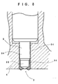
- FIG. 1 illustrates one embodiment of the present invention, wherein a copper sleeve 60 is inserted between a tip portion 8 of a nozzle body and an engine head 4.
- a copper sleeve 60 is inserted between a tip portion 8 of a nozzle body and an engine head 4.
- FIG. 12 shows an injection valve analogous to the conventional injection valve shown in FIG. 16.
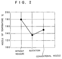
- An air layer is formed in an area S indicated by a dashed line, and temperatures of the tip portions of these nozzles are compared with each other in FIG. 2.
- the temperature of the tip portion of the nozzle body of the present invention is 135°C, and there is obtained a reduction in temperature as large as 45°C relative to an injection valve (the temperature of the tip portion of the nozzle body is 180°C) which does not have the copper sleeve 10 inserted therein.
- the temperature of the tip portion of the nozzle body is 150 reduction effect as compared to that of the present invention.
- the heat insulation member which is formed from a material having a low heat conductivity and which is provided in at least part of the area of the nozzle body exposed to the combustion chamber, shields the nozzle body from the heat supplied from the combustion chamber. Accordingly, the temperature of the tip portion of the nozzle body is reduced so as to be maintained lower than the 90%-distillation temperature of fuel, thereby more effectively suppressing the generation and accumulation of deposits on the internal surface of the nozzle hole and hence resulting in further effective reduction of variations in a flow rate.
- the heat insulation member according to the fourth invention is formed from a substance having a low heat conductivity and covers the area of the nozzle body exposed to the combustion chamber or a part of that area. The operation and effects of this heat insulation member when it shields the nozzle body from the heat flowing from the combustion chamber will be described.
- the amount of heat flowing into the tip portion of the nozzle body becomes smaller, enabling reductions in the temperature of the tip portion of the nozzle body.
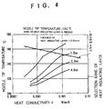
- the ratio of heat conductivity ⁇ (W/mm/K) of the material constituting the thermal insulation member to the thickness "t" (mm) of the thermal insulation member; i.e., ⁇ /t is set to be smaller than 8.5 x 10 -4 .
- the effect of reducing the temperature of the tip portion of the nozzle body is dependent on the heat conductivity of the area of the nozzle body exposed to the combustion chamber or of a member attached to a part of the exposed area.
- a trial calculation was made with regard to the heat conductivity of the member attached to the exposed area of the nozzle body inserted in the combustion chamber, as well as to the effect of reducing the temperature of the tip portion of the nozzle body obtained when the thickness of the member was changed.
- FIG. 8 illustrates the results of such trial calculation.
- boundary conditions are set such that the temperature of the tip portion of the nozzle body becomes 180°C when the tip portion is directly exposed to the combustion chamber.
- the temperature of the tip portion of the nozzle becomes 168°C, provided that the thickness of the member is 0.35 mm.
- the temperature is reduced to 150°C with a thickness of 1.2 mm, 140°C with a thickness of 2 mm, and to 130°C with a thickness of 4 mm. The lower the heat conductivity of the member, the thinner the thickness of the member can be made.
- the temperature of the tip portion of the nozzle body can be maintained at a temperature lower than or equal to 150°C. This temperature is lower than the 90%-distillation temperature of ordinary gasoline.
- this type of injection valve the generation and accumulation of deposits on the internal surface of the nozzle hole are suppressed, thereby enabling implementation of an injection valve which reduces variations in its flow rate.
- the thermal insulation member is annularly provided at the lowermost end of the nozzle body so as to surround the nozzle hole. Therefore, the deposit reduction fuel injection valve has an effect of effectively shielding the nozzle body from the heat supplied from the combustion chamber.
- an outlet of the nozzle hole is positioned above the lowermost end of the thermal insulation member. Therefore, the outlet of the nozzle hole does not project into the combustion chamber, and there is produced an effect of reducing the amount of deposit to be deposited because the outlet port is set back from the combustion chamber.
- a deposit reduction fuel injection valve comprises a fuel injection valve 1 which has a nozzle hole 3 formed on a lower tip end of a tip portion 8 of a nozzle body so as to face a combustion chamber 2 of an internal-combustion engine and which directly feeds fuel to the combustion chamber.
- a temperature adjusting means 5 for adjusting the temperature of the tip portion 8 of the nozzle body having the nozzle hole 3 formed thereon so as to maintain the temperature equal to or lower than a 90%-distillation temperature of fuel is formed between the tip portion 8 of the nozzle body having the nozzle hole 3 formed thereon and an engine head 4.
- the deposit reduction fuel injection valve further comprises a heat flow formation means 6 which dissipates heat supplied to the nozzle 8 to the engine head 4.
- the engine head 4 is provided with a cooling path for circulating cooling water, whereby the temperature of the engine head 4 is maintained at about 80°C.
- the injection valve 1 is fixed to the engine head 4 via an injection valve fixing jig 11.
- a plurality of holes are formed in the fixing jig 11, and bolts are screwed into these holes.
- the bolts are fitted to the engine head 4.
- forces to fasten the bolts are exerted on the engine head 4 via the fixing jig 11, the injection valve flange 12, and the gasket 13, whereby the injection valve 1 is fixed to the engine head 4.
- the combustion chamber 2 is formed from a space which is surrounded by the engine head 4, a cylinder, and a piston (not shown). A mixed gas consisting of fuel and air is combusted within the combustion chamber 2 thereby to produce a large quantity of heat.
- the heat flow formation means 6 ensures a new path over which heat flows from the tip portion 8 of the nozzle body to the engine head 4.
- the heat flowing into the tip portion 8 of the nozzle body can be easily dissipated to the engine head 4.
- a heat conduction promoting member 60 is formed from a material having a high heat conductivity and is disposed between the outer side surface of a cylindrical base portion of the tip portion 8 of the nozzle body and the inner wall surface of the engine head 4.
- the heat conduction promoting member 60 is formed from a hollow cylindrical copper sleeve 61 whose base material is copper having a high heat conductivity.
- the copper sleeve 61 is formed so as to have given inner and outer diameters and is disposed between an outer circumferential surface 81 of the tip portion 8 of the nozzle body and an inner circumferential surface of a nozzle insertion hole 41 of the engine head 4.
- the heat conduction promoting member 60 is inserted into the annular space formed between the nozzle 8 and the nozzle insertion hole 41 of the engine head 4.
- the sleeve 61 has its inner circumferential surface held in close contact with the outer circumferential surface 81 of the cylindrical base portion of the tip portion 8 so as to minimize the heat resistance of the contact surface between the inner circumferential surface 81 of the sleeve 61 and the outer circumferential surface of the nozzle 8.
- the outer circumferential surface of the copper sleeve 61 is brought into close contact with the inner circumferential surface of the engine head 4, thereby minimizing the heat resistance of the contact surface between them.
- the copper sleeve 61 which is made of a material having a high heat conductivity and constitute the heat conduction promoting member 60, is inserted between the side surface 81 of the nozzle 8 and the engine head 4, so that a heat flow path is formed while the heat resistance between the side surface 81 of the nozzle 8 and the engine head 4 is minimized. As a result, the heat flowing into the nozzle 8 is dissipated to the engine head 4.
- the deposit reduction fuel injection valve according to the first embodiment which operates in the above described manner, a new path over which heat flows from the nozzle 8 to the engine head 4 is ensured.
- the heat flowed into the nozzle 8 is effectively dissipated to the engine head 4, thereby reducing the temperature of the tip portion 8 of the nozzle body having the nozzle hole 3 formed therein.
- the fuel is in the liquefied state on the inner surface of the nozzle hole 3, thereby suppressing the generation and accumulation of deposits on the internal surface of the nozzle hole 3 and hence resulting in reduced variations in a flow rate.
- the operation and effects of the deposit reduction fuel injection valve according to the first embodiment are stably ensured even when the injection valve 1 is fitted to the engine 4 utilizing screws provided on the injection valve 1, without use of the fixing jig 11 in the first embodiment.
- a deposit reduction fuel injection valve according to a second embodiment is different from that of the first embodiment in that an outer circumferential surface 621 of the copper sleeve 62 and the inner circumferential wall of the engine head 4 are tapered in order to increase the degree of close-contact between the copper sleeve 62, which comes into contact with the Side surface 81 of the tip portion 8 of the nozzle body, and the inner circumferential wall of the engine head 4.
- the difference is principally described hereinbelow.
- the copper sleeve 62 is sandwiched between and held in close contact with the engine head 4 and the nozzle 8 in a wedge-like manner when the injection valve 1 is fitted to the engine head 4.
- the surfaces of the copper sleeve 61 and the engine head 4 which are in contact with each other are tapered, and they are brought into close contact with each other in a wedge-like manner.
- a heat flow path whose contact resistance is minimized is provided between the nozzle 8 and the engine head 4, thereby facilitating the dissipation to the engine head 4 of the heat flowing to the tip portion 8 of the nozzle body.
- the surfaces of the copper sleeve 61 and the engine head 4 which are in contact with each other are tapered, so that the close contact state is improved, and the contact area between the copper sleeve and the engine head is increased.
- the above-described effect can be obtained by tapering the surfaces of the nozzle 8 and the copper sleeve which are in contact with each other, or by tapering the surfaces of the nozzle 8, the copper sleeve 62, and the engine head 4 which are in contact with each other.
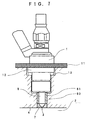
- a deposit reduction fuel injection valve according to a third embodiment is different from that in the first embodiment in the following point. Namely, as illustrated in FIG. 7, in addition to the heat conduction promoting member 60 which is made of a material having a high heat conductivity and which is interposed between the side surface of the tip portion 8 of the nozzle body and the engine head 4, the deposit reduction fuel injection valve is provided with a heat insulation member 7 which is provided on the area of the nozzle 8 exposed in the combustion chamber 2 and which shields the nozzle 8 from heat fed from the combustion chamber 2. The difference is principally described hereinbelow.
- the copper sleeve 61 which contains copper having a high heat conductivity as a base material is inserted between the nozzle 8 and the engine head 4.
- the tapered-tip portion of the nozzle 8, which is exposed to the combustion chamber 2, is covered with the annular heat insulation member 7 having a low heat conductivity.
- a circular hole is formed at the center of the heat insulation member 7 so as to constitute the nozzle hole 3 having a given axial length.
- a heat flow path is formed between the side surface of the nozzle 8 and the engine head 4 by the copper sleeve 61, which serves as the heat conduction promoting member 60 in a state in which the heat resistance between the side surface of the nozzle 8 and the engine head 4 is minimized, enabling facilitation of dissipation to the engine head 4 of the heat flowing into the nozzle.
- the exposed area of the nozzle 8 in the combustion chamber 2 is covered with the heat insulation member 7 which is made of a material having a low heat conductivity, thereby interrupting or regulating the heat flowing to the nozzle 8 from the combustion chamber 2.
- the copper sleeve 61 is brought into close contact with the nozzle 8 and the engine head 4, minimizing the heat resistance of the contact surfaces between them.
- the heat supplied to the tip portion of the nozzle 8 from the combustion chamber 2 can be substantially interrupted by the heat insulation member 7. More specifically, not only the dissipation of heat from the nozzle 8 but also interruption of entry of the heat to the nozzle 8 are effected, and the temperature of the tip portion of the nozzle 8 is therefore reduced more efficiently, thereby effectively suppressing the generation and accumulation of deposits on the internal surface of the nozzle hole 3 and hence resulting in reduced variations in a flow rate.
- a deposit reduction fuel injection valve is different from that of the first embodiment in that the tip portion 8 of the nozzle body has a two-staged structure as illustrated in FIG. 8; namely, a structure comprising a base large-diameter section 84 and a tip small-diameter section 85, and in that a thin tube-like copper sleeve 64 is brought into contact with the outer circumferential surface of the base large-diameter section 84, as well as with the overall inner circumferential wall of the nozzle insertion hole of the engine head 4.
- a heat insulation member 94 having a low heat conductivity is interposed between a tip end of the tip small-diameter section 85 and the copper sleeve 64.
- the copper sleeve 64 has its lower edge bent in a radially inward direction of the nozzle 8 at a position corresponding to the lower end of the inner circumferential wall of the nozzle insertion hole of the engine head 4.
- An annular hole is formed at the center of the copper sleeve so as to constitute the nozzle hole 3 formed on a tip taper end of the tip portion 8 of the nozzle body
- the heat insulation member 94 is provided so as to come into contact with the outer circumferential wall of the tip portion small-diameter section 85 of the nozzle 8 and its tapered lowermost end.
- a tapered circular hole is formed at the lower center of the copper sleeve in consideration of a spray pattern.
- the nozzle hole 3 of the nozzle 8 is positioned a predetermined distance above the lower end of the heat insulation member 94 (the circular hole of the copper sleeve 64).
- a heat flow path is formed between the side surface of the nozzle 8 and the engine head 4 by the copper sleeve 61, which serves as the heat conduction promoting member 60 in a state in which the heat resistance between the side surface of the nozzle 8 and the engine head 4 is minimized, enabling facilitation of dissipation to the engine head 4 of the heat flowing into the nozzle.
- the exposed area of the nozzle 8 in the combustion chamber 2 is covered with the heat insulation member 94 which is made of a material having a low heat conductivity, thereby interrupting or regulating the heat flowing to the nozzle 8 from the combustion chamber 2.
- the copper sleeve 64 is brought into close contact with the nozzle 8 and the engine head 4, minimizing the heat resistance of the contact surfaces between them.
- the heat supplied to the tip portion of the nozzle 8 from the combustion chamber 2 can be interrupted substantially by the heat insulation member 94. More specifically, not only the dissipation of heat from the nozzle 8 but also interruption of entry of the heat to the nozzle 8 are effected, and the temperature of the tip portion of the nozzle 8 is therefore reduced more efficiently, thereby effectively suppressing the generation and accumulation of deposits on the internal surface of the nozzle hole 3 and hence resulting in reduced variations in a flow rate.
- the outlet of the nozzle hole 3 is positioned above the lowermost edge of the heat insulation member 94.
- the copper sleeve 64 has its lower edge inwardly folded over in the radial direction of the nozzle 8 at the lower end of the inner circumferential wall of the nozzle insertion hole of the engine head 4 so as to cover the lowermost outer periphery of the heat insulation member 94.
- the heat flowing to the heat insulation member 94 and the nozzle 8 from the combustion chamber 2 is interrupted, and the nozzle 8 is cooled and regulated by the copper sleeve 64 cooled by the engine head 4 which is cooled by the cooling water. Therefore, there is produced an effect of more efficiently reducing the temperature of the tip portion of the nozzle 8.
- the inventors verified that the fuel injection valve of the fourth embodiment could have reduced the temperature of the tip portion of the nozzle about 60°C relative to the conventional fuel injection valve.
- the present invention is also capable of adopting an embodiment in which the copper sleeve is fitted into the nozzle insertion hole of the engine head above the lowermost end of the nozzle insertion hole without folding over the lower edge of the copper sleeve.
- This structure prevents the copper sleeve from being exposed to the combustion chamber 2, while ensuring the maximum area for dissipating heat from the nozzle 8 to the engine head.
- a deposit reduction fuel injection valve including a nozzle hole, formed on a tip portion of a nozzle body so as to face a combustion chamber of an internal combustion engine, for injecting directly fuel in said combustion chamber, and a temperature adjusting system for adjusting a temperature of said tip portion of said nozzle body having said nozzle hole so as to maintain the temperature equal to or lower than a 90%-distillation temperature of fuel.
Landscapes
- Engineering & Computer Science (AREA)
- Chemical & Material Sciences (AREA)
- Combustion & Propulsion (AREA)
- Mechanical Engineering (AREA)
- General Engineering & Computer Science (AREA)
- Fuel-Injection Apparatus (AREA)
Applications Claiming Priority (2)
| Application Number | Priority Date | Filing Date | Title |
|---|---|---|---|
| JP262563/96 | 1996-09-10 | ||
| JP26256396A JPH1089192A (ja) | 1996-09-10 | 1996-09-10 | デポジット低減式燃料噴射弁 |
Publications (1)
| Publication Number | Publication Date |
|---|---|
| EP0828075A1 true EP0828075A1 (de) | 1998-03-11 |
Family
ID=17377551
Family Applications (1)
| Application Number | Title | Priority Date | Filing Date |
|---|---|---|---|
| EP97115623A Withdrawn EP0828075A1 (de) | 1996-09-10 | 1997-09-09 | Brennstoffeinspritzventil mit Niederschlagreduzierung |
Country Status (2)
| Country | Link |
|---|---|
| EP (1) | EP0828075A1 (de) |
| JP (1) | JPH1089192A (de) |
Cited By (11)
| Publication number | Priority date | Publication date | Assignee | Title |
|---|---|---|---|---|
| EP1081374A3 (de) * | 1999-09-03 | 2003-04-16 | Delphi Technologies, Inc. | Einspritzdüse |
| WO2005050004A1 (de) * | 2003-11-21 | 2005-06-02 | Robert Bosch Gmbh | Brennstoffeinspritzventil |
| EP1455083A3 (de) * | 2003-03-07 | 2005-10-19 | Nissan Motor Company, Limited | Kühlanordnung für Brennstoffeinspritzventil |
| US7261089B2 (en) | 2003-08-18 | 2007-08-28 | Robert Bosch Gmbh | Fuel injector nozzle seal |
| DE102006013880A1 (de) * | 2006-03-25 | 2007-11-08 | Dr.Ing.H.C. F. Porsche Ag | Brennstoffeinspritzanlage |
| US7744014B2 (en) | 2002-07-25 | 2010-06-29 | Continental Automotive Gmbh | Injection module |
| CN101311516B (zh) * | 2004-11-02 | 2011-09-28 | 丰田自动车株式会社 | 用于内燃机的控制装置 |
| WO2017089229A1 (de) * | 2015-11-27 | 2017-06-01 | Robert Bosch Gmbh | Injektoranordnung mit thermoschutzhülse |
| WO2017102216A1 (de) * | 2015-12-14 | 2017-06-22 | Robert Bosch Gmbh | Kraftstoffinjektor |
| WO2017102245A1 (de) * | 2015-12-15 | 2017-06-22 | Robert Bosch Gmbh | Injektor mit verbessertem wärmeverhalten |
| FR3101920A1 (fr) * | 2019-10-14 | 2021-04-16 | Renault S.A.S. | Protecteur de nez d’injecteur direct d’essence avec bouclier thermique |
Families Citing this family (5)
| Publication number | Priority date | Publication date | Assignee | Title |
|---|---|---|---|---|
| JP2001090630A (ja) * | 1999-09-27 | 2001-04-03 | Mazda Motor Corp | 筒内噴射式エンジンの燃料供給装置 |
| JP2001132582A (ja) | 1999-11-10 | 2001-05-15 | Mitsubishi Electric Corp | 筒内噴射用燃料噴射弁 |
| JP2010138778A (ja) * | 2008-12-11 | 2010-06-24 | Mitsubishi Heavy Ind Ltd | 燃料噴射弁の冷却構造 |
| KR101307080B1 (ko) | 2011-07-19 | 2013-09-11 | 현대중공업 주식회사 | 가스 엔진용 예연소실 구조체 |
| JP6250366B2 (ja) * | 2013-11-08 | 2017-12-20 | 三菱重工業株式会社 | 内燃機関の燃料噴射弁温度抑制機構およびこれを備えた内燃機関 |
Citations (8)
| Publication number | Priority date | Publication date | Assignee | Title |
|---|---|---|---|---|
| GB719952A (en) * | 1951-04-24 | 1954-12-08 | Saurer Ag Adolph | An improved fuel injection nozzle for diesel engines |
| US2777431A (en) * | 1953-08-28 | 1957-01-15 | Maschf Augsburg Nuernberg Ag | Injection nozzle arrangement |
| GB2066895A (en) * | 1980-01-03 | 1981-07-15 | Bosch Gmbh Robert | Fuel injection nozzle with a heat protecting sleeve for internal combustion engines |
| JPS591103B2 (ja) | 1978-03-13 | 1984-01-10 | 住友金属工業株式会社 | 塗油量自動制御方法 |
| JPS62103456A (ja) | 1985-10-30 | 1987-05-13 | Aisan Ind Co Ltd | 電磁式燃料噴射弁 |
| JPS63151970A (ja) | 1986-12-17 | 1988-06-24 | Canon Inc | カラー記録装置 |
| JPS6365823B2 (de) | 1978-09-15 | 1988-12-16 | Bosch Gmbh Robert | |
| JPH085336Y2 (ja) | 1989-09-20 | 1996-02-14 | いすゞ自動車株式会社 | 噴射ノズルの冷却構造 |
-
1996
- 1996-09-10 JP JP26256396A patent/JPH1089192A/ja active Pending
-
1997
- 1997-09-09 EP EP97115623A patent/EP0828075A1/de not_active Withdrawn
Patent Citations (8)
| Publication number | Priority date | Publication date | Assignee | Title |
|---|---|---|---|---|
| GB719952A (en) * | 1951-04-24 | 1954-12-08 | Saurer Ag Adolph | An improved fuel injection nozzle for diesel engines |
| US2777431A (en) * | 1953-08-28 | 1957-01-15 | Maschf Augsburg Nuernberg Ag | Injection nozzle arrangement |
| JPS591103B2 (ja) | 1978-03-13 | 1984-01-10 | 住友金属工業株式会社 | 塗油量自動制御方法 |
| JPS6365823B2 (de) | 1978-09-15 | 1988-12-16 | Bosch Gmbh Robert | |
| GB2066895A (en) * | 1980-01-03 | 1981-07-15 | Bosch Gmbh Robert | Fuel injection nozzle with a heat protecting sleeve for internal combustion engines |
| JPS62103456A (ja) | 1985-10-30 | 1987-05-13 | Aisan Ind Co Ltd | 電磁式燃料噴射弁 |
| JPS63151970A (ja) | 1986-12-17 | 1988-06-24 | Canon Inc | カラー記録装置 |
| JPH085336Y2 (ja) | 1989-09-20 | 1996-02-14 | いすゞ自動車株式会社 | 噴射ノズルの冷却構造 |
Cited By (15)
| Publication number | Priority date | Publication date | Assignee | Title |
|---|---|---|---|---|
| US7331535B2 (en) | 1999-09-03 | 2008-02-19 | Delphi Technologies, Inc. | Injection nozzle |
| EP1553287A1 (de) * | 1999-09-03 | 2005-07-13 | Delphi Technologies, Inc. | Einspritzdüse |
| EP1081374A3 (de) * | 1999-09-03 | 2003-04-16 | Delphi Technologies, Inc. | Einspritzdüse |
| US7744014B2 (en) | 2002-07-25 | 2010-06-29 | Continental Automotive Gmbh | Injection module |
| EP1455083A3 (de) * | 2003-03-07 | 2005-10-19 | Nissan Motor Company, Limited | Kühlanordnung für Brennstoffeinspritzventil |
| US7261089B2 (en) | 2003-08-18 | 2007-08-28 | Robert Bosch Gmbh | Fuel injector nozzle seal |
| WO2005050004A1 (de) * | 2003-11-21 | 2005-06-02 | Robert Bosch Gmbh | Brennstoffeinspritzventil |
| DE10354465B4 (de) * | 2003-11-21 | 2014-07-17 | Robert Bosch Gmbh | Brennstoffeinspritzventil |
| CN101311516B (zh) * | 2004-11-02 | 2011-09-28 | 丰田自动车株式会社 | 用于内燃机的控制装置 |
| DE102006013880A1 (de) * | 2006-03-25 | 2007-11-08 | Dr.Ing.H.C. F. Porsche Ag | Brennstoffeinspritzanlage |
| WO2017089229A1 (de) * | 2015-11-27 | 2017-06-01 | Robert Bosch Gmbh | Injektoranordnung mit thermoschutzhülse |
| WO2017102216A1 (de) * | 2015-12-14 | 2017-06-22 | Robert Bosch Gmbh | Kraftstoffinjektor |
| WO2017102245A1 (de) * | 2015-12-15 | 2017-06-22 | Robert Bosch Gmbh | Injektor mit verbessertem wärmeverhalten |
| FR3101920A1 (fr) * | 2019-10-14 | 2021-04-16 | Renault S.A.S. | Protecteur de nez d’injecteur direct d’essence avec bouclier thermique |
| WO2021074053A1 (fr) * | 2019-10-14 | 2021-04-22 | Renault S.A.S | Protecteur de nez d'injecteur direct d'essence avec bouclier thermique |
Also Published As
| Publication number | Publication date |
|---|---|
| JPH1089192A (ja) | 1998-04-07 |
Similar Documents
| Publication | Publication Date | Title |
|---|---|---|
| US5860394A (en) | Method for suppressing formation of deposits on fuel injector and device for injecting fuel | |
| JPH1089192A (ja) | デポジット低減式燃料噴射弁 | |
| US6119658A (en) | Fuel nozzle injecting onto the combustion space of an internal combust | |
| US7484499B2 (en) | Combustion seal | |
| US7028918B2 (en) | Fuel injector having a nozzle with improved cooling | |
| US7455056B2 (en) | Valve device | |
| US7383818B1 (en) | Fuel injector with secondary combustion seal | |
| US20170051713A1 (en) | Nozzle combustion shield and sealing member with improved heat transfer capabilities | |
| US6260531B1 (en) | Valve seat insert | |
| EP1553287A1 (de) | Einspritzdüse | |
| Du et al. | Experimental Investigation on the Effects of Injection Parameters on the Air‐Assisted Diesel Spray Characteristics | |
| JP2002098000A (ja) | ディーゼル機関の燃料噴射弁冷却装置 | |
| JP2000186615A (ja) | 直噴火花点火式内燃機関 | |
| JP2009052491A (ja) | 内燃機関 | |
| US5666933A (en) | Sleeveless cylinder block without marginal plating coating | |
| CN211819674U (zh) | 冷却水套结构及具有其的发动机 | |
| JP3532430B2 (ja) | 燃料噴射弁 | |
| EP2157312B1 (de) | Einspritzventil | |
| CN223359254U (zh) | 缸盖总成、发动机和车辆 | |
| RU2173788C2 (ru) | Клапанная форсунка для впрыскивания топлива | |
| MXPA05003819A (es) | Camisa interior para cilindros. | |
| GB2073335A (en) | Internal combustion engine gasket | |
| CN223578096U (zh) | 燃料喷射装置、发动机及车辆 | |
| JP2000170627A (ja) | 燃料噴射ノズルの取付構造 | |
| JPH0236941Y2 (de) |
Legal Events
| Date | Code | Title | Description |
|---|---|---|---|
| PUAI | Public reference made under article 153(3) epc to a published international application that has entered the european phase |
Free format text: ORIGINAL CODE: 0009012 |
|
| 17P | Request for examination filed |
Effective date: 19970909 |
|
| AK | Designated contracting states |
Kind code of ref document: A1 Designated state(s): DE FR GB |
|
| AX | Request for extension of the european patent |
Free format text: AL;LT;LV;RO;SI |
|
| AKX | Designation fees paid |
Free format text: DE FR GB |
|
| RBV | Designated contracting states (corrected) |
Designated state(s): DE FR GB |
|
| STAA | Information on the status of an ep patent application or granted ep patent |
Free format text: STATUS: THE APPLICATION HAS BEEN WITHDRAWN |
|
| 18W | Application withdrawn |
Withdrawal date: 19990917 |