EP0829082B1 - Optischer datenspeicher - Google Patents
Optischer datenspeicher Download PDFInfo
- Publication number
- EP0829082B1 EP0829082B1 EP96920060A EP96920060A EP0829082B1 EP 0829082 B1 EP0829082 B1 EP 0829082B1 EP 96920060 A EP96920060 A EP 96920060A EP 96920060 A EP96920060 A EP 96920060A EP 0829082 B1 EP0829082 B1 EP 0829082B1
- Authority
- EP
- European Patent Office
- Prior art keywords
- data
- fluorescence
- data carrying
- carrying structure
- fluorescent
- Prior art date
- Legal status (The legal status is an assumption and is not a legal conclusion. Google has not performed a legal analysis and makes no representation as to the accuracy of the status listed.)
- Expired - Lifetime
Links
- 230000003287 optical effect Effects 0.000 title abstract description 19
- 238000013500 data storage Methods 0.000 title description 55
- 230000000171 quenching effect Effects 0.000 claims abstract description 52
- 238000010791 quenching Methods 0.000 claims abstract description 50
- 238000000034 method Methods 0.000 claims abstract description 39
- 239000000463 material Substances 0.000 claims abstract description 37
- 239000007850 fluorescent dye Substances 0.000 claims abstract description 35
- 230000005855 radiation Effects 0.000 claims abstract description 20
- 239000000758 substrate Substances 0.000 claims abstract description 20
- 239000000975 dye Substances 0.000 claims description 40
- 230000004048 modification Effects 0.000 claims description 17
- 238000012986 modification Methods 0.000 claims description 17
- 229920000642 polymer Polymers 0.000 claims description 14
- 230000008569 process Effects 0.000 claims description 9
- 230000005284 excitation Effects 0.000 claims description 8
- 239000000126 substance Substances 0.000 claims description 6
- 239000007795 chemical reaction product Substances 0.000 claims description 5
- 239000011159 matrix material Substances 0.000 claims description 5
- 229920001169 thermoplastic Polymers 0.000 claims description 5
- 229920003229 poly(methyl methacrylate) Polymers 0.000 claims description 4
- 239000004926 polymethyl methacrylate Substances 0.000 claims description 4
- 230000008859 change Effects 0.000 claims description 3
- 230000005012 migration Effects 0.000 claims description 3
- 238000013508 migration Methods 0.000 claims description 3
- 230000009467 reduction Effects 0.000 claims description 2
- 230000004044 response Effects 0.000 claims description 2
- 230000003595 spectral effect Effects 0.000 claims description 2
- 125000000332 coumarinyl group Chemical class O1C(=O)C(=CC2=CC=CC=C12)* 0.000 claims 1
- 230000001678 irradiating effect Effects 0.000 claims 1
- 150000004893 oxazines Chemical class 0.000 claims 1
- 125000001834 xanthenyl group Chemical class C1=CC=CC=2OC3=CC=CC=C3C(C12)* 0.000 claims 1
- 238000003860 storage Methods 0.000 abstract description 13
- 239000010410 layer Substances 0.000 description 126
- 230000015572 biosynthetic process Effects 0.000 description 8
- 238000001514 detection method Methods 0.000 description 7
- 150000001875 compounds Chemical class 0.000 description 6
- 229920006254 polymer film Polymers 0.000 description 6
- 238000010521 absorption reaction Methods 0.000 description 5
- 230000005540 biological transmission Effects 0.000 description 5
- 238000006243 chemical reaction Methods 0.000 description 5
- 230000001419 dependent effect Effects 0.000 description 5
- 230000005281 excited state Effects 0.000 description 5
- 239000003153 chemical reaction reagent Substances 0.000 description 4
- 238000002679 ablation Methods 0.000 description 3
- 238000000576 coating method Methods 0.000 description 3
- 238000009792 diffusion process Methods 0.000 description 3
- 238000010438 heat treatment Methods 0.000 description 3
- 229910052751 metal Inorganic materials 0.000 description 3
- 239000002184 metal Substances 0.000 description 3
- 239000004416 thermosoftening plastic Substances 0.000 description 3
- 230000005641 tunneling Effects 0.000 description 3
- 230000015556 catabolic process Effects 0.000 description 2
- IWWWBRIIGAXLCJ-BGABXYSRSA-N chembl1185241 Chemical compound C1=2C=C(C)C(NCC)=CC=2OC2=C\C(=N/CC)C(C)=CC2=C1C1=CC=CC=C1C(=O)OCC IWWWBRIIGAXLCJ-BGABXYSRSA-N 0.000 description 2
- 239000011248 coating agent Substances 0.000 description 2
- 238000011161 development Methods 0.000 description 2
- 230000005264 electron capture Effects 0.000 description 2
- 238000005516 engineering process Methods 0.000 description 2
- 238000002474 experimental method Methods 0.000 description 2
- 239000010408 film Substances 0.000 description 2
- 230000005283 ground state Effects 0.000 description 2
- 238000005286 illumination Methods 0.000 description 2
- 230000036039 immunity Effects 0.000 description 2
- 230000007246 mechanism Effects 0.000 description 2
- 230000008018 melting Effects 0.000 description 2
- 238000002844 melting Methods 0.000 description 2
- 239000002245 particle Substances 0.000 description 2
- 150000003254 radicals Chemical class 0.000 description 2
- 230000008707 rearrangement Effects 0.000 description 2
- 239000010409 thin film Substances 0.000 description 2
- BCHZICNRHXRCHY-UHFFFAOYSA-N 2h-oxazine Chemical compound N1OC=CC=C1 BCHZICNRHXRCHY-UHFFFAOYSA-N 0.000 description 1
- GOLORTLGFDVFDW-UHFFFAOYSA-N 3-(1h-benzimidazol-2-yl)-7-(diethylamino)chromen-2-one Chemical compound C1=CC=C2NC(C3=CC4=CC=C(C=C4OC3=O)N(CC)CC)=NC2=C1 GOLORTLGFDVFDW-UHFFFAOYSA-N 0.000 description 1
- GJCOSYZMQJWQCA-UHFFFAOYSA-N 9H-xanthene Chemical compound C1=CC=C2CC3=CC=CC=C3OC2=C1 GJCOSYZMQJWQCA-UHFFFAOYSA-N 0.000 description 1
- VEXZGXHMUGYJMC-UHFFFAOYSA-M Chloride anion Chemical compound [Cl-] VEXZGXHMUGYJMC-UHFFFAOYSA-M 0.000 description 1
- 238000000862 absorption spectrum Methods 0.000 description 1
- 230000003213 activating effect Effects 0.000 description 1
- 230000004075 alteration Effects 0.000 description 1
- 239000004411 aluminium Substances 0.000 description 1
- 229910052782 aluminium Inorganic materials 0.000 description 1
- XAGFODPZIPBFFR-UHFFFAOYSA-N aluminium Chemical compound [Al] XAGFODPZIPBFFR-UHFFFAOYSA-N 0.000 description 1
- 230000008901 benefit Effects 0.000 description 1
- 238000001311 chemical methods and process Methods 0.000 description 1
- 150000001805 chlorine compounds Chemical class 0.000 description 1
- 238000002425 crystallisation Methods 0.000 description 1
- 230000008025 crystallization Effects 0.000 description 1
- -1 cyanine compound Chemical class 0.000 description 1
- 230000006735 deficit Effects 0.000 description 1
- 230000000779 depleting effect Effects 0.000 description 1
- 238000009826 distribution Methods 0.000 description 1
- 230000005684 electric field Effects 0.000 description 1
- 230000008030 elimination Effects 0.000 description 1
- 238000003379 elimination reaction Methods 0.000 description 1
- 230000008020 evaporation Effects 0.000 description 1
- 238000001704 evaporation Methods 0.000 description 1
- 239000005357 flat glass Substances 0.000 description 1
- 238000001917 fluorescence detection Methods 0.000 description 1
- 150000002222 fluorine compounds Chemical class 0.000 description 1
- 230000009477 glass transition Effects 0.000 description 1
- 230000001771 impaired effect Effects 0.000 description 1
- 238000011065 in-situ storage Methods 0.000 description 1
- 229910052809 inorganic oxide Inorganic materials 0.000 description 1
- 238000006317 isomerization reaction Methods 0.000 description 1
- QDLAGTHXVHQKRE-UHFFFAOYSA-N lichenxanthone Natural products COC1=CC(O)=C2C(=O)C3=C(C)C=C(OC)C=C3OC2=C1 QDLAGTHXVHQKRE-UHFFFAOYSA-N 0.000 description 1
- 230000031700 light absorption Effects 0.000 description 1
- 238000004519 manufacturing process Methods 0.000 description 1
- 230000000873 masking effect Effects 0.000 description 1
- 230000005499 meniscus Effects 0.000 description 1
- 238000012544 monitoring process Methods 0.000 description 1
- 239000004033 plastic Substances 0.000 description 1
- 229920003023 plastic Polymers 0.000 description 1
- 239000002861 polymer material Substances 0.000 description 1
- 230000000644 propagated effect Effects 0.000 description 1
- 239000011241 protective layer Substances 0.000 description 1
- 238000006462 rearrangement reaction Methods 0.000 description 1
- PYWVYCXTNDRMGF-UHFFFAOYSA-N rhodamine B Chemical compound [Cl-].C=12C=CC(=[N+](CC)CC)C=C2OC2=CC(N(CC)CC)=CC=C2C=1C1=CC=CC=C1C(O)=O PYWVYCXTNDRMGF-UHFFFAOYSA-N 0.000 description 1
- 230000035945 sensitivity Effects 0.000 description 1
- 238000001228 spectrum Methods 0.000 description 1
- 238000004528 spin coating Methods 0.000 description 1
- 238000005507 spraying Methods 0.000 description 1
- 230000007480 spreading Effects 0.000 description 1
- 238000003892 spreading Methods 0.000 description 1
- 150000003568 thioethers Chemical class 0.000 description 1
- 238000012546 transfer Methods 0.000 description 1
- 230000001131 transforming effect Effects 0.000 description 1
- 238000002834 transmittance Methods 0.000 description 1
- 239000001018 xanthene dye Substances 0.000 description 1
Images
Classifications
-
- G—PHYSICS
- G11—INFORMATION STORAGE
- G11B—INFORMATION STORAGE BASED ON RELATIVE MOVEMENT BETWEEN RECORD CARRIER AND TRANSDUCER
- G11B7/00—Recording or reproducing by optical means, e.g. recording using a thermal beam of optical radiation by modifying optical properties or the physical structure, reproducing using an optical beam at lower power by sensing optical properties; Record carriers therefor
- G11B7/24—Record carriers characterised by shape, structure or physical properties, or by the selection of the material
- G11B7/241—Record carriers characterised by shape, structure or physical properties, or by the selection of the material characterised by the selection of the material
-
- G—PHYSICS
- G11—INFORMATION STORAGE
- G11B—INFORMATION STORAGE BASED ON RELATIVE MOVEMENT BETWEEN RECORD CARRIER AND TRANSDUCER
- G11B7/00—Recording or reproducing by optical means, e.g. recording using a thermal beam of optical radiation by modifying optical properties or the physical structure, reproducing using an optical beam at lower power by sensing optical properties; Record carriers therefor
- G11B7/24—Record carriers characterised by shape, structure or physical properties, or by the selection of the material
- G11B7/2407—Tracks or pits; Shape, structure or physical properties thereof
- G11B7/24085—Pits
-
- G—PHYSICS
- G11—INFORMATION STORAGE
- G11B—INFORMATION STORAGE BASED ON RELATIVE MOVEMENT BETWEEN RECORD CARRIER AND TRANSDUCER
- G11B7/00—Recording or reproducing by optical means, e.g. recording using a thermal beam of optical radiation by modifying optical properties or the physical structure, reproducing using an optical beam at lower power by sensing optical properties; Record carriers therefor
- G11B7/004—Recording, reproducing or erasing methods; Read, write or erase circuits therefor
- G11B7/0045—Recording
- G11B7/00451—Recording involving ablation of the recording layer
-
- G—PHYSICS
- G11—INFORMATION STORAGE
- G11B—INFORMATION STORAGE BASED ON RELATIVE MOVEMENT BETWEEN RECORD CARRIER AND TRANSDUCER
- G11B7/00—Recording or reproducing by optical means, e.g. recording using a thermal beam of optical radiation by modifying optical properties or the physical structure, reproducing using an optical beam at lower power by sensing optical properties; Record carriers therefor
- G11B7/004—Recording, reproducing or erasing methods; Read, write or erase circuits therefor
- G11B7/0045—Recording
- G11B7/00455—Recording involving reflectivity, absorption or colour changes
-
- G—PHYSICS
- G11—INFORMATION STORAGE
- G11B—INFORMATION STORAGE BASED ON RELATIVE MOVEMENT BETWEEN RECORD CARRIER AND TRANSDUCER
- G11B7/00—Recording or reproducing by optical means, e.g. recording using a thermal beam of optical radiation by modifying optical properties or the physical structure, reproducing using an optical beam at lower power by sensing optical properties; Record carriers therefor
- G11B7/004—Recording, reproducing or erasing methods; Read, write or erase circuits therefor
- G11B7/005—Reproducing
- G11B7/0052—Reproducing involving reflectivity, absorption or colour changes
-
- G—PHYSICS
- G11—INFORMATION STORAGE
- G11B—INFORMATION STORAGE BASED ON RELATIVE MOVEMENT BETWEEN RECORD CARRIER AND TRANSDUCER
- G11B7/00—Recording or reproducing by optical means, e.g. recording using a thermal beam of optical radiation by modifying optical properties or the physical structure, reproducing using an optical beam at lower power by sensing optical properties; Record carriers therefor
- G11B7/24—Record carriers characterised by shape, structure or physical properties, or by the selection of the material
- G11B7/241—Record carriers characterised by shape, structure or physical properties, or by the selection of the material characterised by the selection of the material
- G11B7/242—Record carriers characterised by shape, structure or physical properties, or by the selection of the material characterised by the selection of the material of recording layers
- G11B7/244—Record carriers characterised by shape, structure or physical properties, or by the selection of the material characterised by the selection of the material of recording layers comprising organic materials only
-
- G—PHYSICS
- G11—INFORMATION STORAGE
- G11C—STATIC STORES
- G11C11/00—Digital stores characterised by the use of particular electric or magnetic storage elements; Storage elements therefor
- G11C11/56—Digital stores characterised by the use of particular electric or magnetic storage elements; Storage elements therefor using storage elements with more than two stable states represented by steps, e.g. of voltage, current, phase, frequency
-
- G—PHYSICS
- G11—INFORMATION STORAGE
- G11C—STATIC STORES
- G11C13/00—Digital stores characterised by the use of storage elements not covered by groups G11C11/00, G11C23/00, or G11C25/00
- G11C13/04—Digital stores characterised by the use of storage elements not covered by groups G11C11/00, G11C23/00, or G11C25/00 using optical elements ; using other beam accessed elements, e.g. electron or ion beam
Definitions
- the invention concerns a data carrying medium, comprising a fluorescent layer arranged on a substrate, wherein data carrying structures are provided in the fluorescent layer in its surface or from its surface and towards the substrate, and wherein the data carrying structures are provided in a linear or curved path, or in rows and columns in such a manner that the data carrying structures form a matrix, and wherein the fluorescent layer basically comprises fluorescent dye molecules embedded in a transparent polymer base material.
- the invention also concerns a method for generating a data carrying structure in a data carrying medium comprising a fluorescent layer.
- the invention concerns an additional data carrying medium comprising a fluorescent layer arranged on a substrate, wherein data carrying structures are provided in the fluorescent layer in its surface or from its surface and towards the substrate, and wherein the data carrying structures are provided in a linear or curved path, or in rows and columns, the data carrying structures thus forming a matrix, and wherein in that the fluorescent layer basically comprises fluorescent dye molecules embedded in a transparent polymer base material together with an additional method for generating a data carrying structure in the additional data carrying medium.
- the invention concerns a method for generating and detecting a fluorescence excitation in a data carrying structure in the additional data carrying medium.
- the invention concerns digital, optical data storage media of the WORM type (Write Once, Read Many times) where information is written on a thin layer by means of a light pulse of high intensity, typically a strongly focused laser beam. Once data is written on to the layer, it cannot be returned to its original state, but it can be read many times by a weaker light beam which does not further influence the layer's physical state.
- WORM Write Once, Read Many times
- Well known means in this context are thin metal film or flat glass or plastic surfaces or thin polymer film which contains a light-absorbing dye. In most cases such layers are provided between other layers, e.g. reflecting or protective layers. The layer stores information by undergoing a change under the influence of the powerful write light pulse and constitutes the actual data storage layer in the medium.
- optical storage technology is almost exclusively based on the reflective contrast between written marks in the data storage layer or its immediate surroundings.
- a focused laser beam is passed along the data storage layer and changes in the intensity of the reflected laser light are recorded when the beam passes a write mark.
- a typical mark may be in the form of small round or elongated pits, with dimensions of between 0.5 and 7 ⁇ m.
- Optical data storage media which are based on reflection normally employ a strongly reflecting layer, e.g. a vaporized aluminium layer in a multilayer structure where the data storage layer regulates the amount of light incident on the medium which is reflected.
- Data storage media are also known which are based on transmission contrast for light which is detected after having passed through the data storage medium.
- the data storage layer can have a low light transmission capacity in an unknown condition and be more transparent in the write marks which are formed by the powerful write beam.
- the data storage layer can be convened from transparent to opaque in the write marks.
- data storage media are under development in which the contrast is based on stimulated light emission.
- one or more light beams scan the data storage medium which reacts by emitting light of an intensity which is dependent on how the medium was treated early in the write phase.
- the light energy emitted results from. either the release of captured electrons in a high energy state in the data storage layer or down conversion of the scanning light beam.
- Holographic data storage media have also been proposed, with storage of data both on volume and layers.
- An important contrast mechanism in this connection is light-induced alteration of the refraction index.
- Data storage media may also be based on the fluorescent properties of a data storage layer.
- EP-A1-503428 discloses an erasable optical recording medium comprising at least one recording layer which includes a fluorescent material, which may be a fluorescent dye such as a cyanine compound or a photochromic compound e.g. a fluorescent dye compound or spiropylane or fulgide compounds and a photo-reactive bistable quencher capable of quenching the fluorescence emitted from the fluorescent material.
- the bistable quencher may moreover be a compound with a similar structure to that of the photochromic compound.
- the photo-reactive bistable quencher produces two isomers, one having an absorption wavelength spectrum which is different from the other and the one being convertible into the other by an irradiation with light.
- One of these isomers acts as a quencher for quenching the fluorescence emitted by the fluorescent material.
- the photo-reactive bistable quencher is a photochromic compound having a quenching action.
- Information is digitally recorded by utilising the two isomers of the photo-reactive bistable quencher. In the erased state the absorption spectrum of the photo-bistable quencher is that of the long wavelength isomer.
- the information is recorded by causing the fluorescent material to absorb the irradiation light to transfer the absorbed energy to the photo-reactive bistable quencher, causing the photo-reactive quencher to participate in an isomerization reaction from the long wavelength isomer to the short wavelength isomer.
- the reading of the recorded information is performed either by detecting the fluorescence emitted from the fluorescent material or takes place by transforming only a portion of the photo-reactive bistable quencher which is included in the recorded layer in an excessive amount from its short wavelength isomer and back to its long wavelength isomer state, thus activating the quencher.
- US Patent 4 701 880 known an optical information recording/reproducing system wherein the recording medium includes a bit layer which is comprised of a fluorescent substance adjacent to a photoconductive layer, both layers being interposed between conductive layers, at least one of which is transparent. Applying an optical recording beam to a site on the recording medium with a simultaneous application of a voltage by means of conductive layer generates a high electrical field in the bit layer as the resistance of the photoconductive layer is lowered, such that an electric breakdown takes place in the bit layer causing the fluorescent substance to lose fluorescence, whereby information is recorded by fluorescence quenching.
- the bit layer itself is formed by coating a fluorescent substance onto a substrate, the fluorescent substance being selected among activated inorganic oxides, fluorides, sulphides or chlorides.
- European Patent Application 0 415 763 discloses a method for reading information recorded in an information layer comprised of a fluorescent dye.
- the tip of a scanning tunneling microscope is passed over the information layer and generates sufficient voltage to excite the fluorescent dye material to an excited state.
- fluorescence is emitted.
- the writing of the information takes place by providing a track of information bits in the information layer and can be accomplished by an irradiation thereof with light from a focused light source, as well-known in the art.
- the track of information bits can also be generated by using the scanning tunneling microscope.
- information is recorded in information layer by conjointly employing the scanning tunneling microscope operating in a constant voltage mode and a modulated focused light source.
- the fluorescent dye material exhibits two excited states, such that the writing is accomplished by excitation of the fluorescent dye to the second excited state, whereas the first excited state can be used for the reading mode, since the return from the first excited state to the ground state results in fluorescence.
- the bits of information in the information layer are recording by means of depleting the information layer of the fluorescent dye in controlled spot. Fluorescent dye will then be present only in those place where information has not been recorded and upon reading information a bit will be read whenever a decrease in the fluorescence is detected.
- optical data storage media are based on data storage layers of the WORM type, based on one of the following categories:
- the data storage layer permits greater storage density by making the write marks substantially smaller.
- the requirement is to be able to generate write marks or data carrying structures which are smaller than 0.4 ⁇ m and which can easily be read, and thus requiring that the data storage layer must not have particles or topographical structures which are larger than 0.1 ⁇ m.
- the data storage layer's sensitivity should be sufficiently high to enable it to use light with a short pulse duration in order to achieve high spatial resolution and moreover to permit the use of short write pulse durations, thus obtaining correspondingly short thermal diffusion lengths.
- the normal situation is that a write mark or a data carrying structure in a conventional storage medium has a write mark which during reading will be in one of two possible states, corresponding to a binary 0 or a binary 1.
- the data storage layer's reflectance or transmittance is normally measured and a simple decision threshold decides whether the layer is exposed to a writing laser pulse or not at the location for the data carrying structure.
- a special object of the invention in the present case is to provide data carrying structures which can store more than 1 bit and above all provide a data carrying structure which permits coding of a grey scale, thus substantially increasing the data storage density in relation to present day known optical data storage media.
- experiments have been conducted with electron capture in a multilevel storage layer developed by Optex Inc., who claim that it is possible to employ 16 grey scale levels, corresponding to 4 bits.
- This medium is read by generating fluorescence from electrons captured during writing and the possibility arises of storing a multilevel code by monitoring the strength of the fluorescence.
- the object of the present invention is to provide a data storage medium where the position of the focal point in the data storage layer is altered by changing the angle of incidence for light which is used for writing in the data storage layer, thus making it possible to form a dense pattern of data storage structures which are angle of incidence addressable, e.g. by means of microlenses provided on the data storage medium's surface. as disclosed in NO patent application no. 900443.
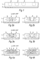
- Fig. 1 illustrates a data carrying medium which comprises a fluorescent layer 1 arranged on a substrate 2.
- the fluorescent layer there are provided in its surface or from its surface and towards the substrate data carrying structures generally indicated by 3.
- the data carrying structures 3 will be able to be arranged in a linear or curved path, for example spirally as on a CD disc, or also in rows and columns, thus forming a matrix.
- the fluorescent layer 1 comprises dye molecules 4 (fig. 2) which are advantageously embedded in a transparent polymer base material, for example of modified polymethylmethacrylate (MPMMA).
- the dye molecules 4 may, for example, be rhodamine molecules.
- Each of the data carrying structures 3 has a specific degree of quenching for the fluorescence which is emitted from a data carrying structure 3 when it is irradiated with fluorescence exciting radiation (fig. 6).
- the degree of quenching for the fluorescence refers to the fluorescence which is emitted by the virgin, fluorescent layer, i.e. a layer without data carrying structures and which is not irradiated with laser light in order to generate data carrying structures 3.
- the degree of quenching for the fluorescence in such a case can refer to a region of the virgin, fluorescent layer and with a surface area equal to the area of the data carrying structure 3 at the surface of the fluorescent layer 1.
- the degree of quenching for the fluorescence which is emitted by a data carrying structure 3 indicates the value of the datum which is stored in the data carrying structure.
- each data carrying structure 3 can represent a binary 0 or a binary 1 and the space between each data carrying structure can represent a binary 1 or a binary 0, the fluorescence which is emitted in this space naturally being the fluorescence emitted by the virgin, fluorescent layer 1.
- a specific degree of quenching can be assigned to the data carrying structures in several ways. It can be achieved advantageously as illustrated in figs. 2a. b in which the write pulse, i.e. a beam of laser light, is incident on the fluorescent layer 1 (fig. 2a), softening and melting the material in the fluorescent layer, thus causing a data carrying structure 3 (fig. 2b) to be formed in the form of a pit in this layer.
- the processes involved can be a thermoplastic deformation, ablation or another heat-induced transport process.
- the pit i.e. the data carrying structure 3
- the degree of quenching for the fluorescence being substantially determined by the geometry of the heat-induced pit, in practice, e.g., depth and diameter.
- the fluorescence in the fluorescent layer 1 can also be modified on the molecular level, e.g. as in figs. 3a, b, by directing a beam of laser light towards the surface of the fluorescent layer 1, and by causing at least a part of the fluorescent dye molecules 4 to migrate out of the data carrying structure 3 indicated by a dotted line (fig. 3a).
- a dotted line fig. 3a
- the degree of quenching will substantially be determined by the ratio between the number of fluorescent dye molecules in the structure 3, respectively before and after the fluorescence has been modified by means of the laser beam.
- Figs. 4a, b illustrate how a data carrying structure 3 can be formed in the fluorescent layer 1 by causing a chemical reaction between the fluorescent dye molecules 4 and reagent molecules 5 which are illustrated in the figure as circles with an x, while the dye molecules 4 are illustrated as open circles.
- a data carrying structure is obtained in which a portion of the molecules in the fluorescent layer 1 are now reaction products 6, illustrated here as filled circles, of the dye molecules 4 and reagent molecules 5, since the reaction product's molecules 6 do not fluoresce when irradiated.
- the data carrying structure 3 thereby created obtains a degree of quenching for the fluorescence which is determined by the number of fluorescent dye molecules 4 remaining in the data carrying structure after the fluorescence modification.
- the irradiation with laser light causes the dye molecules 4 to react chemically with the reagent molecules.
- a number of other chemical processes which can be initiated by irradiation with laser light are well known to those skilled in the art and one example which can be mentioned is that it is possible to obtain fluorescence quenching by radical formation, splitting of the dye molecules or rearrangement of the dye molecules or allowing the dye molecules to react chemically with other molecules.
- the degree of quenching for the fluorescence corresponds to the value of the datum which is assigned to the data carrying structure, this datum corresponding to the value of a specific level in a predetermined multilevel code.
- the degree of quenching for the fluorescence refers to the fluorescence which is emitted by the virgin, fluorescent layer in a region thereof which corresponds to the area for the data carrying structure 3 in the fluorescent layer 1. It thereby also becomes possible to store several bits in one and the same data carrying structure.
- the use of two different degrees of quenching for the fluorescence gives a bivalent or binary code, since one degree of quenching can correspond to binary 0 and a second degree of quenching to binary 1.
- the value of the datum the data carrying structure 3 stores in fig. 2 being given by the size of the data carrying structure or the pit, in fig. 3 by the number of dye molecules 4 remaining in the data carrying structure, and in fig. 4 by the number of dye molecules 4 which have not undergone a chemical reaction with the reagent molecules 5 and lost the ability to fluoresce.
- the laser beam is modulated according to a predetermined modulation procedure which comprises a number of modulation stages corresponding to levels in the stipulated multilevel code.
- the laser beam can be modulated with regard to a number of parameters.
- the modulation can be advantageously achieved by varying the pulse parameters, the modulation value being naturally commensurable with the value of the datum which is assigned to the data carrying structure 3 when it is generated and which again represents a specific level in the stipulated multilevel code.
- an opaque layer 7 with good radiation-absorbing properties and which disappears when irradiated with the laser light during the generation of the data carrying structures 3.
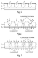
- Fig. 6 illustrates schematically data carrying structures 3 1 - 3 4 in the form of heat-induced pits of different sizes, the data carrying structures from 3 1 - 3 4 representing in consecutive order a code with four levels and thereby each being capable of storing 2 bits.
- 3 1 here represents binary 11, i.e. 3 1 and 3 4 0.
- Fig. 7 illustrates the same arrangement as in fig. 6, but the levels in each data structure 3, 3 1 -3 4 are determined by the number of fluorescent dye molecules 4 in the data structure created. The desired number which corresponds to a specific level in the stipulated multilevel code can be obtained either by causing a migration of the dye molecules 4 out of the data carrying structure 3 1 or by the dye molecules 4 reacting with other molecules and forming non-fluorescent reaction products.
- the data carrying structure 3 1 is illustrated schematically by two dye molecules 4 and is assigned the binary value 11, i.e. 3, while the data carrying structure 3 4 is schematically illustrated by eight dye molecules 4 and assigned the value 0.
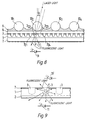
- Fig. 8 illustrates a more practical embodiment of the data carrying medium according to the invention.
- a heat-absorbing layer 7 which is opaque to both the fluorescent radiation which is emitted by the fluorescent layer and the radiation which is used to produce the fluorescence.
- the opaque layer 7 will, however, disappear or become transparent at the point where radiation is absorbed which is used to create the underlying data carrying structure 3.
- the fluorescent layer 1 is arranged above a transparent substrate 2 which has high transmissivity with regard to the fluorescent radiation emitted by the data carrying structure 3.
- optically active structures 10 1 -10 4 are advantageously provided on the surface of the data carrying medium. These optically active structures are illustrated in fig.
- microlenses 10 1 -10 4 are microlenses 10 1 -10 4 and partially embedded in a binding layer 9 which is placed over a transparent spacing layer 8.
- the opaque layer 7 is illustrated here arranged between the spacing layer 8 and the fluorescent layer 1, but it should be understood that if desired the layer 7 can be omitted, even though it entails certain advantages with regard to, e.g., reading of the data stored in the data carrying structures 3, since the opaque layer 7 is not influenced by the fluorescence exciting light radiation, and gives the data carrying medium increased noise immunity when reading the stored data.
- the microlenses 10 1 -10 4 can be formed from monodisperse spheres, as described in more detail in the above-mentioned NO patent application no. 900443.
- the microlenses 10 1 -10 4 are optically-geometrically arranged in unambiguous correspondence with one or more data carrying structures.
- each individual microlens 10 which typically has a diameter of a few ten ⁇ m, will be assigned to a very large number of data carrying structures, for example several thousand, since the extent of a single data carrying structure 3 compared with the dimensions of the microlens can be very small, for example well below 1 ⁇ m.
- the optically active structures can also be diffractive structures, as described in more detail in the same applicant's simultaneously submitted International patent application no. PCT/NO96/00156.
- the beam of incident light whether it be laser light for generating the data carrying structures 3 or light radiation in order to cause fluorescence excitation in the data carrying structures 3, is unambiguously focused on a specific point in the fluorescent layer 1 in order to create a data carrying structure 3 or on a data carrying structure 3 in order thereby to cause fluorescence for reading the datum stored therein.
- a method is employed for generation and detection of a fluorescence excitation in the data carrying structures. This is also illustrated in principle in fig. 8.
- a light beam with an angle of incidence ⁇ strikes a microlens 10 2 and is focused on one of the data carrying structures 3 22 .
- the fluorescence exciting light beam must have a wavelength which is tuned to the spectral response of the fluorescent dye molecules 4 in the data carrying structure 3.
- the fluorescence which is generated by excitation and emitted from the data carrying structure is detected in a detector device 11 which may be provided at a distance from the data carrying medium and placed above or below it. In figs.
- a calibration or control can advantageously be undertaken of the read values by simultaneously reading data carrying reference structures which in consecutive order represent the value of each individual level in the stipulated multilevel code.
- These reference structures can advantageously be included in the number of data carrying structures which are assigned to one of the optically active structures and in this context reference should be made to figs. 6 and 7, where it will be seen that the data carrying structures 3 illustrated there represent reference structures for a code with four levels, the data carrying structures 3 1 -3 4 in consecutive order representing the individual stages in this four-level code which permits storage of up to 2 bits in each of the data structures.
- a data carrying medium In a data carrying medium according to the present invention and with the use of methods for generating a data carrying structure 3 according to the present invention it is possible to obtain very small data carrying structures, since the dye molecules 4 which are evenly distributed in the fluorescent layer 1 give a spatial definition which in the last resort is only limited by the distance between and the dimensions of the dye molecules. It is worth noting, however, that other factors can contribute to the reduction in the size of the data carrying structure or affect the fluorescent layer in a disadvantageous manner. For example the creation of clusters or crystallization of the dye molecules can give the fluorescent layer a grainy structure, which can be a problem if a high concentration of dye molecules is required in order to obtain sufficient fluorescence intensity in the fluorescent layer.
- the extent of the high temperature range which is generated during the formation of the data carrying structures will be crucial. This range can extend outside the directly illuminated volume, dependent on pulse duration and the heat transport parameters in the fluorescent layer and in the substrate. Even in cases where the fluorescence quenching is only restricted to the volume in the fluorescent layer which is subjected to an intense illumination during the formation of the data carrying structures, i.e. where no thermal diffusion extension of the volume of the data carrying structure occurs, it can be necessary to use a fluorescent layer which, in order to ensure sufficient light absorption, becomes so thick that it can lead to a loss in the definition of the site for the data carrying structure.
- a multilevel coding of the data carrying structures 3 in the fluorescent layer 1 is obtained by suitable control of the intensity and the energy of the light radiation during the generation of the data carrying structures and the writing of data.
- the remaining fluorescence from the data carrying structures can be quantified by employing a well defined light pulse in order to generate fluorescence from the data carrying structure during the reading, thereby indicating a multibit condition in the data carrying structure.
- the fluorescence quenching is provided by, e.g., modulating the intensity and the pulse energy of the incident light.
- the ratios between the chosen modulation parameters for the write beam can be linear, nonlinear or threshold-dependent. As an example of the latter, it can be mentioned that where the fluorescence quenching is effected by local heating by absorption of the light, the fluorescence quenching will not become effective until a threshold temperature is reached, e.g. the glass transition temperature for the polymer base material in the fluorescent layer 1.
- a threshold temperature e.g. the glass transition temperature for the polymer base material in the fluorescent layer 1.
- the number of achievable levels when using multilevel coding of the data carrying structures 3 is dependent on the equipment which is used for the generation and implies that consideration must be given to both the write and read speeds as well as the data storage density in the data storage medium in addition to the stipulated costs for equipment and data storage media.
- the fluorescent layer is illuminated at different sites for the data carrying structures by a relatively weak light beam, which produces the fluorescence of the data carrying structures. Even though the incident, fluorescence exciting light strikes the data carrying structure or the fluorescent layer from different directions, in every case the fluorescent light which is emitted by the data carrying structure will be emitted isotropically (fig. 9). Even though only a relatively small portion of the total fluorescence emission from a data carrying structure is directed in such a manner that it is intercepted by the detection system, in a first approximation this portion will be the same for all positions of the data carrying structures and exposure directions.
- an opaque layer 7 over the fluorescent layer can help to increase the noise immunity of the data storage medium according to the invention, either by absorbing reflections on the interfaces of the fluorescent layer or by masking reflected or scattered fluorescent light from adjacent data carrying structures when the detection of the fluorescent light is implemented by focusing through optically active structures 10.
- a number of different dyes can be employed, e.g. coumarin, xanthene or oxazine dyes and firm base materials, e.g. thermohardened polymers or thermoplastic polymers.
- a number of possible coating processes for thin film can be applied to the layer, such as spin-coating, electrostatic spray coating, knife spreading or meniscus coating.
- the layer thickness should be less than 1 ⁇ m and the dye's density and layer thickness must be controlled very accurately in those cases where multilevel coding of the data carrying structures is to be employed. This lies well within the possibilities offered by present day technology for mass production processes, even where a curved spacing layer is used concentrically with the spherical microlenses and a corresponding curved fluorescent layer.
- the data medium according to the invention is designed in the form of a hybrid layer as illustrated in fig. 8, dye/polymer systems can also be used where fluorescence quenching is not possible.
- the basically opaque layer 5 which is arranged above the fluorescent layer 4, e.g. in the form of a hole-forming metal layer, light is prevented from reaching the fluorescent layer, apart from areas where the opaque layer is influenced during the writing process. During reading fluorescence will only be able to be excited from those openings which are formed in the opaque layer.
- This method which is based on the use of a controlled fluorescence excitation, permits the use of writable layers which are not fluorescent in the wave length range where the detection takes place, but which can nevertheless be irradiated in order to form an opaque or completely transmitting state, corresponding to binary 0 or binary 1 respectively.
- the layer is also irradiated in such a manner that the degree of transmission (the absorption) varies in several stages, thus making it possible to store more than one bit in each data carrying structure in the fluorescent layer.
- Four stages or transmissivity levels will, e.g., permit the storage of 2 bits. This implies a considerable expansion of the possibilities for choosing material for a practical implementation of the data carrying medium.
Landscapes
- Engineering & Computer Science (AREA)
- Computer Hardware Design (AREA)
- Optical Recording Or Reproduction (AREA)
- Optical Record Carriers And Manufacture Thereof (AREA)
- Holo Graphy (AREA)
Claims (27)
- Ein Verfahren zum Erzeugen von datentragenden Strukturen in einem datentragenden Medium,
worin das datentragende Medium eine Fluoreszenzschicht (1) umfasst, die auf einem Substrat (2) aufgebracht ist und grundsätzlich Fluoreszenzfarbstoffmoleküle (4) einschließt, die in einem durchsichtigen Polymergrundmaterial eingebettet sind,
worin die datentragenden Strukturen (3) in der Fluoreszenzschicht (1) in ihrer Oberfläche oder von ihrer Oberfläche und in Richtung des Substrats (2) auf einer linearen oder gekrümmten Bahn, oder in Reihen und Spalten auf solche Weise, dass die datentragenden Strukturen (3) eine Matrix bilden, bereitgestellt werden,
wobei das Verfahren zur Erzeugung der datentragenden Strukturen durchgeführt wird, indem ein kontrollierter Betrag von Strahlungsenergie auf das datentragende Medium an der vorgesehenen Stelle einer datentragenden Struktur zur Erzeugung derselben durch einen bestimmten Grad an Auslöschung gerichtet wird,
wobei der Betrag der Strahlungsenergie durch eine Modulation derselben gemäß eines vorbestimmten Modulationsverfahrens gesteuert wird,
wobei das Modulationsverfahren eine oder mehrere Modulationsstufen umfasst, wobei die Anzahl der angewendeten Modulationsstufen der Anzahl des speziellen Grades der Auslöschung entspricht, so dass die Anzahl des speziellen Grades der Auslöschung in der datentragenden Struktur durch strahlungsinduzierte Verminderung des Betrags an Fluoreszenzmaterial in dem datentragenden Medium an der Stelle der datentragenden Struktur erreicht wird,
wobei die Zahl der Farbstoffmoleküle (4) in jeder datentragenden Struktur mit dem spezielle Grad der Auslöschung der entsprechenden datentragenden Struktur variiert,
wobei jeder der datentragenden Strukturen (3) ein Datenwert entsprechend der Intensität der Fluoreszenz zugewiesen wird, die von der datentragenden Struktur (3) emittiert wird, wenn sie mit fluoreszenzanregender Strahlung bestrahlt wird,
wobei sich der spezielle Grad der Auslöschung der Fluoreszenz auf die ungelöschte Fluoreszenz bezieht, die von einer unbehandelten Fluoreszenzschicht (1) emittiert wird, in einem Gebiet, dessen Oberflächenausmaß gleich zur Fläche der datentragenden Struktur (3) an der Oberfläche der Fluoreszenzschicht (1 )ist,
wobei durch das Verfahren zur Erzeugung der datentragenden Struktur auf diese Weise einen Prozess zum Schreiben von Daten auf das datentragende Medium eingeführt wird. - Ein Verfahren nach Anspruch 1, gekennzeichnet das Erzeugen durch Strahlungsenergie einer datentragenden Struktur, die von einem Laserstrahl bereitgestellt wird, der gemäß dem Modulationsverfahren moduliert wird.
- Ein Verfahren nach Anspruch 1, dadurch gekennzeichnet, dass jede datentragende Struktur (3) mit einem speziellen Grad an Auslöschung erzeugt wird, die einen Wert in einem vorbestimmten Mehrebenen Code darstellt.
- Ein Verfahren nach Anspruch 1, dadurch gekennzeichnet dass die datentragende Struktur (3) als eine thermisch induzierte Vertiefung in der Fluoreszenzschicht erzeugt wird, wobei die datentragende Struktur (3) einen bestimmten Grad an Fluoreszenzlöschung erhält, im wesentlichen bestimmt durch die Geometrie der thermisch induzierten Vertiefung.
- Ein Verfahren nach Anspruch 1, dadurch gekennzeichnet dass die datentragende Struktur (3) als ein fluoreszenz-modifiziertes Gebiet in der Fluoreszenzschicht (1) erzeugt wird, wobei die Fluoreszenzmodifikation bereitgestellt wird, indem eine Wanderung von zumindest einem Teil grundsätzlich fluoreszierender Farbstoffmoleküle (4) aus der datentragenden Struktur heraus verursacht wird, so dass der Grad der Fluoreszenzmodifikation dem Verhältnis zwischen der Anzahl der Fluoreszenzfarbstoffmoleküle in dem Bereich der datentragenden Struktur (3) vor beziehungsweise nach der Fluoreszenzmodifikation entspricht, wobei die datentragende Struktur (3) einen bestimmten Grad von Fluoreszenzlöschung erfährt, der durch die Anzahl der Farbstoffmoleküle, die in der datentragenden Struktur (3) nach der Fluoreszenzmodifikation verbleiben, bestimmt wird.
- Ein Verfahren nach Anspruch 1, dadurch gekennzeichnet dass die datentragende Struktur (3) als ein fluoreszenz-modifiziertes Gebiet in der Fluoreszenzschicht (1) erzeugt wird, wobei die Fluoreszenzmodifikation bereitgestellt wird, indem eine chemische Veränderung von zumindest einem Teil grundsätzlich fluoreszierender Farbstoffmoleküle (4) verursacht wird, mit dem Ergebnis, dass sie nicht mehr fluoreszieren, so dass der Grad der Fluoreszenzmodifikation dem Verhältnis zwischen der Anzahl der Fluoreszenzfarbstoffmoleküle in dem Bereich der datentragenden Struktur (3) vor beziehungsweise nach der Fluoreszenzmodifikation entspricht, wobei die datentragende Struktur (3) einen bestimmten Grad von Fluoreszenzlöschung erfährt, der durch die Anzahl der Farbstoffmoleküle, die in der datentragenden Struktur (3) nach der Fluoreszenzmodifikation verbleiben, bestimmt wird.
- Ein Verfahren nach Anspruch 6, dadurch gekennzeichnet dass die chemisch veränderten, nicht-fluoreszierenden Farbstoffmoleküle (6) als ein Reaktionsprodukt der grundsätzlich fluoreszierenden Farbstoffmoleküle (4) und zusätzlichen Molekülen (5), die in dem Grundmaterial vorhanden sind, erzeugt werden, wobei die zusätzlichen Moleküle (5) chemisch mit den Farbstoffmolekülen (4) unter dem Einfluss von Strahlungsenergie, wie sie auf das datentragende Medium angewandt wird, reagieren.
- Ein datentragendes Medium umfassend:worin die datentragenden Strukturen (3) in der Fluoreszenzschicht (1) in ihrer Oberfläche oder von ihrer Oberfläche und in Richtung des Substrats (2) bereitgestellt werden und die datentragenden Strukturen (3) auf einer linearen oder gekrümmten Bahn, oder in Reihen und Spalten bereitgestellt werden, so dass die datentragenden Strukturen (3) eine Matrix bilden,eine Fluoreszenzschicht (1), die auf einem Substrat aufgebracht ist,
und worin diese Fluoreszenzschicht (1) grundsätzlich Fluoreszenzfarbstoffmoleküle (4) umfasst, die in einem durchsichtigen Polymergrundmaterial eingebettet sind,
dadurch gekennzeichnet, dass
jede dieser datentragenden Strukturen (3) gemäß dem Bezugswert, den sie repräsentiert, einen speziellen Grad der Fluoreszenzlöschung aufweist, die aus der datentragenden Struktur (3) emittiert wird, wenn sie mit einer fluoreszenzanregenden Strahlung bestrahlt wird,
wobei der Wert, den die datentragende Struktur (3) repräsentiert, einer speziellen Ebene in einem vorbestimmten Mehrebenen Code entspricht,
wobei jede Ebene einem speziellen Grad der Fluoreszenzlöschung entspricht,
wobei sich der spezielle Grad der Fluoreszenzlöschung auf die ungelöschte Fluoreszenz bezieht, die von einer unbehandelten Fluoreszenzschicht (1) emittiert wird, in einem Gebiet, dessen Oberflächenausmaß gleich zur Fläche der datentragenden Struktur (3) an der Oberfläche der Fluoreszenzschicht (1) ist. - Ein datentragendes Medium nach Anspruch 8, dadurch gekennzeichnet, dass der Mehrebenen Code ein zweiwertiger oder binärer Code ist.
- Ein datentragendes Medium nach Anspruch 8, dadurch gekennzeichnet, dass der Mehrebenen Code ein Graustufen Code ist.
- Ein datentragendes Medium nach Anspruch 8, dadurch gekennzeichnet, dass die datentragende Struktur (3) eine thermisch induzierte Vertiefung in der Fluoreszenzschicht ist, wobei die datentragende Struktur (3) einen bestimmten Grad an Fluoreszenzlöschung erhält, im wesentlichen bestimmt durch die Geometrie der thermisch induzierten Vertiefung.
- Ein datentragendes Medium nach Anspruch 8, dadurch gekennzeichnet dass die datentragende Struktur (3) ein fluoreszenz-modifiziertes Gebiet in der Fluoreszenzschicht (1) ist, wobei die Fluoreszenzmodifikation erzeugt wird, indem eine Wanderung von zumindest einem Teil grundsätzlich fluoreszierender Farbstoffmoleküle (4) aus der datentragenden Struktur heraus verursacht wird, so dass der Grad der Fluoreszenzmodifikation dem Verhältnis zwischen der Anzahl der Fluoreszenzfarbstoffmoleküle in dem Bereich der datentragenden Struktur (3) vor beziehungsweise nach der Fluoreszenzmodifikation entspricht, wobei die datentragende Struktur (3) einen bestimmten Grad von Fluoreszenzlöschung erfährt, der durch die Anzahl der Farbstoffmoleküle, die in der datentragenden Struktur (3) nach der Fluoreszenzmodifikation verbleiben, bestimmt wird.
- Ein datentragendes Medium nach Anspruch 8, dadurch gekennzeichnet dass die datentragende Struktur (3) ein fluoreszenz-modifiziertes Gebiet in der Fluoreszenzschicht (1) ist, wobei die Fluoreszenzmodifikation erzeugt wird, indem eine chemische Veränderung von zumindest einem Teil grundsätzlich fluoreszierender Farbstoffmoleküle (4) verursacht wird, mit dem Ergebnis, dass sie nicht mehr fluoreszieren, so dass der Grad der Fluoreszenzmodifikation dem Verhältnis zwischen der Anzahl der Fluoreszenzfarbstoffmoleküle in dem Bereich der datentragenden Struktur (3) vor beziehungsweise nach der Fluoreszenzmodifikation entspricht, wobei die datentragende Struktur (3) einen bestimmten Grad von Fluoreszenzlöschung erfährt, der durch die Anzahl der Farbstoffmoleküle, die in der datentragenden Struktur (3) nach der Fluoreszenzmodifikation verbleiben, bestimmt wird.
- Ein datentragendes Medium nach Anspruch 13, dadurch gekennzeichnet dass die chemisch veränderten, nicht-fluoreszierenden Farbstoffmoleküle (6) ein Reaktionsprodukt der grundsätzlich fluoreszierenden Farbstoffmoleküle (4) und zusätzlichen Molekülen (5), die in dem Grundmaterial vorhanden sind, sind, wobei die zusätzlichen Moleküle (5) chemisch mit den Farbstoffmolekülen (4) unter einem kontrollierten externen physikalischen Einfluss auf die Fluoreszenzschicht (1) reagieren.
- Ein datentragendes Medium nach einem der Ansprüche 8 - 14, dadurch gekennzeichnet, dass das Polymergrundmaterial aus thermogehärteten Polymeren oder thermoplastischen Polymeren, wie Polymethylmethacrylat ausgewählt wird.
- Ein datentragendes Medium nach einem der Ansprüche 8 - 14, dadurch gekennzeichnet, dass die fluoreszierenden Farbstoffmoleküle (4) aus Farbstoffmolekülen ausgewählt werden, die zur Kumarin Klasse, Xanthen Klasse oder Oxazin Klasse gehören.
- Ein datentragendes Medium nach einem der Ansprüche 8 - 14, dadurch gekennzeichnet, dass an der Oberfläche der Fluoreszenzschicht (1) eine Strahlungsabsorbierende Schicht (7) bereitgestellt ist, die sowohl für die Fluoreszenzstrahlung, die von der Fluoreszenzschicht emittiert wird, als auch für die fluoreszenzanregende Strahlung undurchsichtig ist.
- Ein datentragendes Medium nach einem der Ansprüche 8 - 14, dadurch gekennzeichnet, dass das Substrat (2) eine hohe Durchlässigkeit hinsichtlich der Fluoreszenzstrahlung, die von der datentragenden Struktur (3) emittiert wird, aufweist.
- Ein datentragendes Medium nach Anspruch 8, dadurch gekennzeichnet, dass eine Sequenz, eine Reihe oder Spalte von datentragenden Strukturen (3) eine oder mehrere Referenzstrukturen (31-3n) umfasst, die in aufeinanderfolgender Reihe den Wert jeder individuellen Ebene in dem vorherbestimmten Mehrebenen Code repräsentieren.
- Ein datentragendes Medium nach Anspruch 8 oder 17, dadurch gekennzeichnet, dass an der Oberfläche der Fluoreszenzschicht (1) oder der undurchsichtigen strahlenabsorbierenden Schicht (7) optisch aktive Strukturen (10) bereitgestellt sind.
- Ein datentragendes Medium nach Anspruch 20, dadurch gekennzeichnet, dass die optisch aktiven Strukturen (10) Brechungsstrukturen sind und optisch-geometrisch angeordnet sind und unzweideutig einer oder mehreren datentragenden Strukturen (3) zuordenbar sind.
- Ein datentragendes Medium nach Anspruch 21, dadurch gekennzeichnet, dass die optisch aktiven Strukturen (10) Mikrolinsen sind, die teilweise in einer Verbindungsschicht eingebettet sind, erzeugt über der Fluoreszenzschicht (1) oder der undurchsichtigen strahlungsabsorbierenden Schicht, bereitgestellt auf der Fluoreszenzschicht (1).
- Ein datentragendes Medium nach Anspruch 8, dadurch gekennzeichnet, dass die optisch aktiven Strukturen (10) Brechungsstrukturen sind und optisch-geometrisch angeordnet sind und unzweideutig einer oder mehreren datentragenden Strukturen (3) zuordenbar sind.
- Ein Verfahren zum Erzeugen einer datentragenden Struktur (3) in einem datentragenden Medium, umfassend eine Fluoreszenzschicht (1) gemäß den Ansprüchen 8 -23,
dadurch gekennzeichnet, dass
ein Laserstrahl auf einen Punkt auf der Fluoreszenzschicht gerichtet wird,
der Laserstrahl gemäß eines vorbestimmten Modulationsverfahrens moduliert wird, welches eine Anzahl von Modulationsstufen umfasst, die Ebenen in einem vorbestimmten Mehrebenen Code entsprechen, und
der Punkt auf der Fluoreszenzschicht mit dem modulierten Laserstrahl bestrahlt wird, wodurch die datentragende Struktur an diesem Punkt in der Fluoreszenzschicht erzeugt wird,
wobei die datentragende Struktur durch einen thermischen Einfluss auf die Fluoreszenzschicht und/oder einen photoinduzierten Einfluss auf die fluoreszierenden Farbstoffmoleküle, die in der Fluoreszenzschicht bereitgestellt sind, und, möglicherweise, auf andere Moleküle erzeugt wird,
wobei die datentragende Struktur nach der Bestrahlung durch die Modulation des Laserstrahls einen festgelegten Grad an Fluoreszenzlöschung, die von dieser datentragenden Struktur emittiert wird, wenn sie mit fluoreszenzanregender Strahlung bestrahlt wird, erfährt,
wobei der Grad der Fluoreszenzlöschung dem Bezugswert entspricht, der durch die modulierte Bestrahlung der datentragenden Struktur zugewiesen wird, wobei der Bezugswert dem Wert der speziellen Ebene in dem vorherbestimmten Mehrebenen Code entspricht. - Ein Verfahren nach Anspruch 24, dadurch gekennzeichnet, dass der Laserstrahl hinsichtlich einem der folgenden Parameter moduliert wird: Pulsdauer, Pulslänge, Pulsamplitude oder Pulsfrequenz in einer Strahlungskaskade, wobei der Modulationswert vergleichbar zu dem Bezugswert gewählt wird, der durch die Erzeugung der datentragenden Struktur hierzu zugewiesen wird und der eine spezielle Ebene in dem vorbestimmten Mehrebenen Code darstellt.
- Ein Verfahren zum Erzeugen und zum Nachweis einer Fluoreszenzanregung in einer datentragenden Struktur (3) in einem datentragenden Medium, umfassend eine Fluoreszenzschicht (1) gemäß den Ansprüchen 8 -23,
dadurch gekennzeichnet, dass
ein Lichtstrahl auf eine datentragende Schicht gerichtet wird,
die Wellenlänge des Lichtstrahls auf die spektrale Reaktion des fluoreszierenden Farbstoffmoleküls in der datentragenden Struktur abgestimmt wird, und
die Fluoreszenz, die von der datentragenden Struktur emittiert wird, in einer Nachweisvorrichtung, die in einem Abstand von dem datentragenden Medium darüber oder darunter angeordnet ist, nachgewiesen wird,
wobei die Intensität der nachgewiesenen Fluoreszenz dem Bezugswert entspricht, wobei der Bezugswert eine Ebene in einem vorbestimmten Mehrebenen Code darstellt. - Ein Verfahren gemäß Anspruch 26, gekennzeichnet durch den Bezug der nachgewiesene Fluoreszenz, die von einer datentragenden Struktur emittiert wird, auf die Fluoreszenz, die durch Anregung von einer oder mehrerer Referenzstrukturen emittiert wird, die in aufeinanderfolgender Reihe den Wert jeder individuellen Ebene in dem vorherbestimmten Mehrebenen Code repräsentieren.
Applications Claiming Priority (3)
| Application Number | Priority Date | Filing Date | Title |
|---|---|---|---|
| NO952040A NO301144B1 (no) | 1995-05-23 | 1995-05-23 | Optisk datalagring |
| NO952040 | 1995-05-23 | ||
| PCT/NO1996/000125 WO1996037888A1 (en) | 1995-05-23 | 1996-05-22 | Optical data storage |
Publications (2)
| Publication Number | Publication Date |
|---|---|
| EP0829082A1 EP0829082A1 (de) | 1998-03-18 |
| EP0829082B1 true EP0829082B1 (de) | 2002-08-07 |
Family
ID=19898233
Family Applications (1)
| Application Number | Title | Priority Date | Filing Date |
|---|---|---|---|
| EP96920060A Expired - Lifetime EP0829082B1 (de) | 1995-05-23 | 1996-05-22 | Optischer datenspeicher |
Country Status (13)
| Country | Link |
|---|---|
| US (1) | US6115344A (de) |
| EP (1) | EP0829082B1 (de) |
| JP (1) | JPH11507156A (de) |
| KR (1) | KR100292452B1 (de) |
| CN (1) | CN1191035A (de) |
| AT (1) | ATE222018T1 (de) |
| AU (1) | AU705314B2 (de) |
| BR (1) | BR9609203A (de) |
| CA (1) | CA2222026C (de) |
| DE (1) | DE69622860D1 (de) |
| NO (1) | NO301144B1 (de) |
| RU (1) | RU2159471C2 (de) |
| WO (1) | WO1996037888A1 (de) |
Families Citing this family (32)
| Publication number | Priority date | Publication date | Assignee | Title |
|---|---|---|---|---|
| NO303098B1 (no) * | 1995-06-23 | 1998-05-25 | Opticom As | Optisk datalagringsmedium med diffraktive optiske elementer og fremgangsmÕte til skriving og lesing av data i dette |
| US6071671A (en) * | 1996-12-05 | 2000-06-06 | Omd Devices Llc | Fluorescent optical memory |
| AU1384099A (en) * | 1997-11-07 | 1999-05-31 | Omd Devices Llc | Fluorescent composition for the manufacture of cd-rom type optical memory disks |
| JP2000030256A (ja) * | 1998-07-07 | 2000-01-28 | Seiko Instruments Inc | 光記録・再生方法と光記録・再生で用いる記録媒体及び光記録・再生装置 |
| AU3215900A (en) * | 1999-02-12 | 2000-08-29 | Trid Store Ip, L.L.C. | Method of increasing fluorescent signal of optical discs with fluorescent reading |
| US6819649B1 (en) | 1999-02-12 | 2004-11-16 | D Data Inc. | Electroluminescent multilayer optical information storage medium with integrated readout and compositions of matter for use therein |
| US7101655B1 (en) | 1999-02-12 | 2006-09-05 | D Data Inc. | Method for increasing fluorescent signal of optical disks with fluorescent reading and resultant discs |
| EP1155406A1 (de) * | 1999-02-12 | 2001-11-21 | Tri D Store IP, L.L.C. | Auf inkohärentes signal basiertes mehrschichtiges optisches informationsaufzeichnungsmedium |
| EP1130585B1 (de) * | 2000-02-28 | 2011-12-21 | FUJIFILM Corporation | Aufzeichnungsmedium und Informationsaufzeichnung und Wiedergabeverfahren wobei dieses Medium eingesetzt wird |
| AU2001265413A1 (en) * | 2000-06-02 | 2001-12-11 | Trid Store Ip, L.L.C. | Multilayer recordable optical medium with fluorescent reading |
| US7486790B1 (en) | 2000-06-30 | 2009-02-03 | Verification Technologies, Inc. | Method and apparatus for controlling access to storage media |
| US7124944B2 (en) | 2000-06-30 | 2006-10-24 | Verification Technologies, Inc. | Product packaging including digital data |
| WO2002002301A1 (en) | 2000-06-30 | 2002-01-10 | Verification Technologies Inc. | Copy-protected optical media and method of manufacture thereof |
| US6638593B2 (en) | 2000-06-30 | 2003-10-28 | Verification Technologies, Inc. | Copy-protected optical media and method of manufacture thereof |
| US20050063256A1 (en) * | 2000-06-30 | 2005-03-24 | Selinfreund Richard H. | Data storage in optical discs |
| US6483801B1 (en) * | 2000-07-31 | 2002-11-19 | Terastor Corporation | Optical storage devices without mass transfer and spots |
| US7660415B2 (en) | 2000-08-03 | 2010-02-09 | Selinfreund Richard H | Method and apparatus for controlling access to storage media |
| DE10054167A1 (de) * | 2000-11-02 | 2002-05-29 | Tesa Ag | Verfahren zum Herstellen von Hologrammen |
| DE60230110D1 (de) | 2002-02-25 | 2009-01-15 | St Microelectronics Srl | Optisch lesbarer Molekularspeicher hergestellt mit Hilfe von Kohlenstoff-Nanoröhren und Verfahren zum Speichern von Information in diesem Molekularspeicher |
| US20030206320A1 (en) * | 2002-04-11 | 2003-11-06 | Inphase Technologies, Inc. | Holographic media with a photo-active material for media protection and inhibitor removal |
| RU2271043C2 (ru) * | 2002-05-24 | 2006-02-27 | ОАО "Ди Дейта" | Флуоресцентная среда и способ изготовления оптического диска на ее основе |
| JP4368148B2 (ja) * | 2003-06-20 | 2009-11-18 | 独立行政法人理化学研究所 | フィルム、フィルムを用いた光メモリ材料、および、フィルムの製造方法 |
| WO2006043208A1 (en) * | 2004-10-19 | 2006-04-27 | Koninklijke Philips Electronics N.V. | Large sized detector for optimized read-out from an optical data carrier. |
| RU2353982C2 (ru) * | 2006-10-18 | 2009-04-27 | ЗАО "Констеллейшн 3 Ди Восток" | Комбинированный флуоресцентно-отражательный оптический носитель информации и устройство для его считывания |
| CN101308671B (zh) * | 2008-07-10 | 2010-06-02 | 中国科学院化学研究所 | 一种用于超高密度信息存储的数据读出方法 |
| JP2011003258A (ja) * | 2009-06-22 | 2011-01-06 | Sony Corp | 光ピックアップ及び光ディスク装置 |
| JP2012022735A (ja) * | 2010-07-13 | 2012-02-02 | Fujifilm Corp | 光情報記録媒体の記録再生方法 |
| TWI402829B (zh) * | 2010-10-29 | 2013-07-21 | Nat Univ Tsing Hua | 多階記錄方法及其系統 |
| CN105719668B (zh) * | 2016-01-18 | 2018-11-13 | 杭州电子科技大学 | 一种基于光激励材料的光信息存储装置及其存储方法 |
| CN111489768B (zh) * | 2020-04-01 | 2021-06-01 | 华中科技大学 | 一种实现超分辨荧光强度多阶复用的光学存储方法 |
| CN111524539B (zh) * | 2020-04-01 | 2021-06-01 | 华中科技大学 | 一种实现波长复用的超分辨多维的光学存储方法 |
| CN111696588B (zh) * | 2020-05-08 | 2021-06-11 | 华中科技大学 | 一种基于熔融石英荧光信号的光存储方法及系统 |
Citations (2)
| Publication number | Priority date | Publication date | Assignee | Title |
|---|---|---|---|---|
| EP0568753A1 (de) * | 1992-05-07 | 1993-11-10 | International Business Machines Corporation | Optische Speichereinheit mit hoher Datendichte und Informations-, Schreib- und Leseverfahren |
| EP0593037A2 (de) * | 1992-10-13 | 1994-04-20 | Sony Corporation | Datenaufzeichnungsmethode, Datenaufzeichnungsgerät und Datenaufzeichnungsmedium |
Family Cites Families (12)
| Publication number | Priority date | Publication date | Assignee | Title |
|---|---|---|---|---|
| US4663270A (en) * | 1984-04-25 | 1987-05-05 | The Johns Hopkins University | Multistate optical switching and memory using an amphoteric organic charge transfer material |
| JPS60236119A (ja) * | 1984-05-09 | 1985-11-22 | Toshiba Corp | 光学式情報記録再生装置 |
| DE3689891T2 (de) * | 1985-03-06 | 1994-10-20 | Matsushita Electric Ind Co Ltd | Optische Aufzeichnungsmedien mit hoher Dichte, Verfahren zu deren Herstellung und Verfahren um optische Informationen in diesem Medium aufzuzeichnen. |
| SU1278954A1 (ru) * | 1985-04-03 | 1986-12-23 | Предприятие П/Я В-2867 | Дисковый носитель информации дл записи оптических сигналов |
| JPS63133332A (ja) * | 1986-11-25 | 1988-06-06 | Canon Inc | 光学的情報記録担体 |
| JPS647327A (en) * | 1987-03-25 | 1989-01-11 | Casio Computer Co Ltd | Method and apparatus for optical information recording |
| EP0426717B1 (de) * | 1988-07-29 | 1996-04-24 | Riedel-De Haen Aktiengesellschaft | Optische datenspeicher |
| JPH0246538A (ja) * | 1988-08-05 | 1990-02-15 | Sharp Corp | 光メモリ素子 |
| US5268862A (en) * | 1989-04-25 | 1993-12-07 | The Regents Of The Unversity Of California | Three-dimensional optical memory |
| CA2021582A1 (en) * | 1989-08-30 | 1991-03-01 | Harris A. Goldberg | Scanning tunneling microscope utilizing optical fluorescent for reading |
| US5399451A (en) * | 1991-03-14 | 1995-03-21 | Matsushita Electric Industrial Co., Ltd. | Optical recording medium and method for using the same |
| JP2552036B2 (ja) * | 1991-03-14 | 1996-11-06 | 松下電器産業株式会社 | 波長多重光学記録媒体とこれを用いた記録、消去及び再生方法 |
-
1995
- 1995-05-23 NO NO952040A patent/NO301144B1/no not_active Application Discontinuation
-
1996
- 1996-05-22 KR KR1019970708314A patent/KR100292452B1/ko not_active Expired - Fee Related
- 1996-05-22 DE DE69622860T patent/DE69622860D1/de not_active Expired - Lifetime
- 1996-05-22 RU RU97121284/28A patent/RU2159471C2/ru active
- 1996-05-22 CA CA002222026A patent/CA2222026C/en not_active Expired - Fee Related
- 1996-05-22 AU AU58469/96A patent/AU705314B2/en not_active Ceased
- 1996-05-22 US US08/952,421 patent/US6115344A/en not_active Expired - Fee Related
- 1996-05-22 EP EP96920060A patent/EP0829082B1/de not_active Expired - Lifetime
- 1996-05-22 CN CN96195608A patent/CN1191035A/zh active Pending
- 1996-05-22 AT AT96920060T patent/ATE222018T1/de not_active IP Right Cessation
- 1996-05-22 WO PCT/NO1996/000125 patent/WO1996037888A1/en not_active Ceased
- 1996-05-22 BR BR9609203A patent/BR9609203A/pt unknown
- 1996-05-22 JP JP8535174A patent/JPH11507156A/ja active Pending
Patent Citations (2)
| Publication number | Priority date | Publication date | Assignee | Title |
|---|---|---|---|---|
| EP0568753A1 (de) * | 1992-05-07 | 1993-11-10 | International Business Machines Corporation | Optische Speichereinheit mit hoher Datendichte und Informations-, Schreib- und Leseverfahren |
| EP0593037A2 (de) * | 1992-10-13 | 1994-04-20 | Sony Corporation | Datenaufzeichnungsmethode, Datenaufzeichnungsgerät und Datenaufzeichnungsmedium |
Also Published As
| Publication number | Publication date |
|---|---|
| NO952040L (no) | 1996-11-25 |
| KR19990021840A (ko) | 1999-03-25 |
| RU2159471C2 (ru) | 2000-11-20 |
| NO301144B1 (no) | 1997-09-15 |
| AU705314B2 (en) | 1999-05-20 |
| AU5846996A (en) | 1996-12-11 |
| CA2222026A1 (en) | 1996-11-28 |
| WO1996037888A1 (en) | 1996-11-28 |
| KR100292452B1 (ko) | 2001-09-17 |
| CN1191035A (zh) | 1998-08-19 |
| JPH11507156A (ja) | 1999-06-22 |
| NO952040D0 (no) | 1995-05-23 |
| US6115344A (en) | 2000-09-05 |
| DE69622860D1 (de) | 2002-09-12 |
| CA2222026C (en) | 2001-06-19 |
| EP0829082A1 (de) | 1998-03-18 |
| BR9609203A (pt) | 1999-05-11 |
| ATE222018T1 (de) | 2002-08-15 |
Similar Documents
| Publication | Publication Date | Title |
|---|---|---|
| EP0829082B1 (de) | Optischer datenspeicher | |
| CN1121029C (zh) | 光信息记录媒体及其记录和再现方法和设备 | |
| RU97121284A (ru) | Оптическое запоминающее устройство | |
| JP2001522119A (ja) | 多層フォトクロミック光データディスク | |
| US20110090780A1 (en) | Information recording medium and method for producing the same, recording or reproducing method, and optical information recording and reproducing device | |
| JP2001524245A (ja) | 蛍光性光メモリー | |
| JPH11500252A (ja) | 光メモリの中のデータの並行書込みおよび読出しのための方法及び該方法に用いられる書込み/読出しデバイス | |
| US7983117B2 (en) | Optical memories, method for reading and writing such optical memories, and device for reading and writing such memories | |
| US20060072438A1 (en) | Optical information recording substrate and recording/reproducing device using it | |
| US4829505A (en) | Multiple layer optical memory system using second-harmonic-generation readout | |
| JPH0278020A (ja) | 光ディスク駆動システム | |
| US6728154B2 (en) | Three-dimensional optical memory medium and process for producing same | |
| US5195082A (en) | Optical disk structures for electron trapping optical memory media | |
| KR100234244B1 (ko) | 소거 가능한 광매체 | |
| RU2248620C2 (ru) | Оптический многослойный носитель информации, способ его изготовления, способ многослойной записи информации на данный носитель и способ считывания с него информации | |
| CN1282075A (zh) | 光盘 | |
| JP4356048B2 (ja) | 光ディスク | |
| EP0316394A1 (de) | Verfahren zur optischen speicherung von daten und materialien dafür | |
| JPS5941875B2 (ja) | レ−ザ−ビ−ム記録法 | |
| CA1175227A (en) | One step optical imaging method | |
| JP2814759B2 (ja) | 多値光記録媒体およびその読み出し方式 | |
| JP2000098328A (ja) | 光記録媒体及び光記録/読取り方法 | |
| JPH06215380A (ja) | 光メディアのマルチビット・セルラ反射率変調 | |
| JPH07130004A (ja) | 光記録媒体及びその製造方法 | |
| CN1809876A (zh) | 在记录载体上记录信息的方法、记录载体和记录装置 |
Legal Events
| Date | Code | Title | Description |
|---|---|---|---|
| PUAI | Public reference made under article 153(3) epc to a published international application that has entered the european phase |
Free format text: ORIGINAL CODE: 0009012 |
|
| 17P | Request for examination filed |
Effective date: 19971119 |
|
| AK | Designated contracting states |
Kind code of ref document: A1 Designated state(s): AT BE CH DE DK ES FI FR GB IT LI NL SE |
|
| 17Q | First examination report despatched |
Effective date: 19980605 |
|
| GRAG | Despatch of communication of intention to grant |
Free format text: ORIGINAL CODE: EPIDOS AGRA |
|
| GRAG | Despatch of communication of intention to grant |
Free format text: ORIGINAL CODE: EPIDOS AGRA |
|
| GRAG | Despatch of communication of intention to grant |
Free format text: ORIGINAL CODE: EPIDOS AGRA |
|
| GRAH | Despatch of communication of intention to grant a patent |
Free format text: ORIGINAL CODE: EPIDOS IGRA |
|
| RAP1 | Party data changed (applicant data changed or rights of an application transferred) |
Owner name: THIN FILM ELECTRONICS ASA |
|
| GRAH | Despatch of communication of intention to grant a patent |
Free format text: ORIGINAL CODE: EPIDOS IGRA |
|
| GRAA | (expected) grant |
Free format text: ORIGINAL CODE: 0009210 |
|
| AK | Designated contracting states |
Kind code of ref document: B1 Designated state(s): AT BE CH DE DK ES FI FR GB IT LI NL SE |
|
| PG25 | Lapsed in a contracting state [announced via postgrant information from national office to epo] |
Ref country code: NL Free format text: LAPSE BECAUSE OF FAILURE TO SUBMIT A TRANSLATION OF THE DESCRIPTION OR TO PAY THE FEE WITHIN THE PRESCRIBED TIME-LIMIT Effective date: 20020807 Ref country code: LI Free format text: LAPSE BECAUSE OF FAILURE TO SUBMIT A TRANSLATION OF THE DESCRIPTION OR TO PAY THE FEE WITHIN THE PRESCRIBED TIME-LIMIT Effective date: 20020807 Ref country code: IT Free format text: LAPSE BECAUSE OF FAILURE TO SUBMIT A TRANSLATION OF THE DESCRIPTION OR TO PAY THE FEE WITHIN THE PRESCRIBED TIME-LIMIT;WARNING: LAPSES OF ITALIAN PATENTS WITH EFFECTIVE DATE BEFORE 2007 MAY HAVE OCCURRED AT ANY TIME BEFORE 2007. THE CORRECT EFFECTIVE DATE MAY BE DIFFERENT FROM THE ONE RECORDED. Effective date: 20020807 Ref country code: FR Free format text: LAPSE BECAUSE OF NON-PAYMENT OF DUE FEES Effective date: 20020807 Ref country code: FI Free format text: LAPSE BECAUSE OF FAILURE TO SUBMIT A TRANSLATION OF THE DESCRIPTION OR TO PAY THE FEE WITHIN THE PRESCRIBED TIME-LIMIT Effective date: 20020807 Ref country code: CH Free format text: LAPSE BECAUSE OF FAILURE TO SUBMIT A TRANSLATION OF THE DESCRIPTION OR TO PAY THE FEE WITHIN THE PRESCRIBED TIME-LIMIT Effective date: 20020807 Ref country code: BE Free format text: LAPSE BECAUSE OF FAILURE TO SUBMIT A TRANSLATION OF THE DESCRIPTION OR TO PAY THE FEE WITHIN THE PRESCRIBED TIME-LIMIT Effective date: 20020807 Ref country code: AT Free format text: LAPSE BECAUSE OF FAILURE TO SUBMIT A TRANSLATION OF THE DESCRIPTION OR TO PAY THE FEE WITHIN THE PRESCRIBED TIME-LIMIT Effective date: 20020807 |
|
| REF | Corresponds to: |
Ref document number: 222018 Country of ref document: AT Date of ref document: 20020815 Kind code of ref document: T |
|
| REG | Reference to a national code |
Ref country code: GB Ref legal event code: FG4D |
|
| REG | Reference to a national code |
Ref country code: CH Ref legal event code: EP |
|
| REF | Corresponds to: |
Ref document number: 69622860 Country of ref document: DE Date of ref document: 20020912 |
|
| PG25 | Lapsed in a contracting state [announced via postgrant information from national office to epo] |
Ref country code: SE Free format text: LAPSE BECAUSE OF FAILURE TO SUBMIT A TRANSLATION OF THE DESCRIPTION OR TO PAY THE FEE WITHIN THE PRESCRIBED TIME-LIMIT Effective date: 20021107 Ref country code: DK Free format text: LAPSE BECAUSE OF FAILURE TO SUBMIT A TRANSLATION OF THE DESCRIPTION OR TO PAY THE FEE WITHIN THE PRESCRIBED TIME-LIMIT Effective date: 20021107 |
|
| PG25 | Lapsed in a contracting state [announced via postgrant information from national office to epo] |
Ref country code: DE Free format text: LAPSE BECAUSE OF FAILURE TO SUBMIT A TRANSLATION OF THE DESCRIPTION OR TO PAY THE FEE WITHIN THE PRESCRIBED TIME-LIMIT Effective date: 20021108 |
|
| NLV1 | Nl: lapsed or annulled due to failure to fulfill the requirements of art. 29p and 29m of the patents act | ||
| REG | Reference to a national code |
Ref country code: CH Ref legal event code: PL |
|
| PG25 | Lapsed in a contracting state [announced via postgrant information from national office to epo] |
Ref country code: ES Free format text: LAPSE BECAUSE OF FAILURE TO SUBMIT A TRANSLATION OF THE DESCRIPTION OR TO PAY THE FEE WITHIN THE PRESCRIBED TIME-LIMIT Effective date: 20030228 |
|
| PLBE | No opposition filed within time limit |
Free format text: ORIGINAL CODE: 0009261 |
|
| STAA | Information on the status of an ep patent application or granted ep patent |
Free format text: STATUS: NO OPPOSITION FILED WITHIN TIME LIMIT |
|
| 26N | No opposition filed |
Effective date: 20030508 |
|
| PGFP | Annual fee paid to national office [announced via postgrant information from national office to epo] |
Ref country code: GB Payment date: 20070611 Year of fee payment: 12 |
|
| GBPC | Gb: european patent ceased through non-payment of renewal fee |
Effective date: 20080522 |
|
| PG25 | Lapsed in a contracting state [announced via postgrant information from national office to epo] |
Ref country code: GB Free format text: LAPSE BECAUSE OF NON-PAYMENT OF DUE FEES Effective date: 20080522 |