EP0829221A2 - Geschirrspülmaschine mit verbessertem Hydraulikkreislauf - Google Patents
Geschirrspülmaschine mit verbessertem Hydraulikkreislauf Download PDFInfo
- Publication number
- EP0829221A2 EP0829221A2 EP97115615A EP97115615A EP0829221A2 EP 0829221 A2 EP0829221 A2 EP 0829221A2 EP 97115615 A EP97115615 A EP 97115615A EP 97115615 A EP97115615 A EP 97115615A EP 0829221 A2 EP0829221 A2 EP 0829221A2
- Authority
- EP
- European Patent Office
- Prior art keywords
- dishwashing machine
- machine according
- inlets
- feed intake
- hydraulic
- Prior art date
- Legal status (The legal status is an assumption and is not a legal conclusion. Google has not performed a legal analysis and makes no representation as to the accuracy of the status listed.)
- Granted
Links
- 238000004851 dishwashing Methods 0.000 title claims description 32
- 239000012530 fluid Substances 0.000 claims abstract description 40
- 235000021050 feed intake Nutrition 0.000 claims abstract description 13
- 230000008878 coupling Effects 0.000 claims description 10
- 238000010168 coupling process Methods 0.000 claims description 10
- 238000005859 coupling reaction Methods 0.000 claims description 10
- 238000009416 shuttering Methods 0.000 claims 3
- 239000000463 material Substances 0.000 description 6
- 238000005406 washing Methods 0.000 description 6
- 230000005484 gravity Effects 0.000 description 5
- 239000004033 plastic Substances 0.000 description 5
- 238000005507 spraying Methods 0.000 description 5
- 230000008859 change Effects 0.000 description 4
- 238000012423 maintenance Methods 0.000 description 4
- 238000000034 method Methods 0.000 description 4
- 238000007789 sealing Methods 0.000 description 4
- XLYOFNOQVPJJNP-UHFFFAOYSA-N water Substances O XLYOFNOQVPJJNP-UHFFFAOYSA-N 0.000 description 4
- 230000008901 benefit Effects 0.000 description 3
- 238000000465 moulding Methods 0.000 description 3
- 101150114468 TUB1 gene Proteins 0.000 description 2
- 230000000712 assembly Effects 0.000 description 2
- 238000000429 assembly Methods 0.000 description 2
- 238000003780 insertion Methods 0.000 description 2
- 230000037431 insertion Effects 0.000 description 2
- 238000004519 manufacturing process Methods 0.000 description 2
- 230000013011 mating Effects 0.000 description 2
- 230000006866 deterioration Effects 0.000 description 1
- 238000006073 displacement reaction Methods 0.000 description 1
- 230000000694 effects Effects 0.000 description 1
- 238000000605 extraction Methods 0.000 description 1
- 238000007667 floating Methods 0.000 description 1
- 239000011796 hollow space material Substances 0.000 description 1
- 230000000670 limiting effect Effects 0.000 description 1
- 230000007257 malfunction Effects 0.000 description 1
- 230000008569 process Effects 0.000 description 1
- 238000004064 recycling Methods 0.000 description 1
- 230000009467 reduction Effects 0.000 description 1
- 230000002829 reductive effect Effects 0.000 description 1
- 230000008439 repair process Effects 0.000 description 1
- 230000000284 resting effect Effects 0.000 description 1
- 230000000717 retained effect Effects 0.000 description 1
- 239000007921 spray Substances 0.000 description 1
- 230000003068 static effect Effects 0.000 description 1
Images


Classifications
-
- A—HUMAN NECESSITIES
- A47—FURNITURE; DOMESTIC ARTICLES OR APPLIANCES; COFFEE MILLS; SPICE MILLS; SUCTION CLEANERS IN GENERAL
- A47L—DOMESTIC WASHING OR CLEANING; SUCTION CLEANERS IN GENERAL
- A47L15/00—Washing or rinsing machines for crockery or tableware
- A47L15/42—Details
- A47L15/50—Racks ; Baskets
- A47L15/508—Hydraulic connections for racks
-
- A—HUMAN NECESSITIES
- A47—FURNITURE; DOMESTIC ARTICLES OR APPLIANCES; COFFEE MILLS; SPICE MILLS; SUCTION CLEANERS IN GENERAL
- A47L—DOMESTIC WASHING OR CLEANING; SUCTION CLEANERS IN GENERAL
- A47L15/00—Washing or rinsing machines for crockery or tableware
- A47L15/14—Washing or rinsing machines for crockery or tableware with stationary crockery baskets and spraying devices within the cleaning chamber
- A47L15/18—Washing or rinsing machines for crockery or tableware with stationary crockery baskets and spraying devices within the cleaning chamber with movably-mounted spraying devices
- A47L15/22—Rotary spraying devices
- A47L15/23—Rotary spraying devices moved by means of the sprays
Definitions
- the present invention refers to a dishwashing machine of the kind described in the preamble of the annexed Claim 1.
- dishwashing machines usually comprise two crockery baskets, specifically an upper loading basket and a lower loading basket.
- crockery are sprayed by two rotary sprinklers, which spray the wash fluid towards the baskets and are fed with fluid under pressure from a proper wash pump housed in the machine base; the lower sprinkler is generally fed and supported from the bottom by a tubular element directly connected with the pump body.
- Some embodiments have the upper sprinkler fed from the top: a nozzle located in the ceiling of the wash tub which is fed by a duct from the pump, directs a fluid jet downwards; said jet flows across the air to reach a tapered receiving element and is centrally fastened to the machine upper basket.
- the air crossing separating the nozzle from the receiving element is provided to let the basket slide horizontally to carry out the normal extraction or insertion operations associated with loading/unloading of the crockery.
- the tapered receiving element associated with the upper rotary sprinkler and in connection with it normally uses a Venturi tube system to avoid fluid turbulence and flowback.
- the jet of fluid coming out of the nozzle crosses the air and enters the tapered receiving element at high speed, hurting its walls and causing a noise that lasts practically for the whole washing time, which makes the appliance very noisy.
- the upper basket of the dishwashing machine is usually adjustable in height (i.e. it can take at least two different positions, namely a higher and a lower one inside the wash tub to fit the dimensions of the objects to be washed), the air jump may be either greater or smaller according to the usage of the dishwasher. Therefore, it is obvious that when the upper basket is located on its lower position, the fluid flow across the air is greater and as a result the washing under this condition will be more critical. As a matter of fact, when there is such a condition it is more probable that a part of the fluid will not reach the tapered receiving element and fall outside it causing a reduced washing performance. Another negative effect under this condition is the higher noisiness caused by the fluid entering the tapered element.
- dishwashers which are equipped with means suitable to remove the air jump between the upper nozzle and the tapered receiving element during the use of the machine.
- EP-A-401.767 describes a dishwashing machine with its upper basket adjustable in height, where a feeding duct to the upper sprinkler departs from a pump and extends along the side wall and the bottom wall of the wash tub; on the bottom wall of the tub said duct ends in a boxed commutation device with two outlets at different heights having respective closing balls; each ball is housed in a sloped seat located in line with an outlet of the device. Thus, each ball is led by gravity to the closing position of its respective outlet.
- the upper sprinkler of the dishwasher has a connecting tube suitable to be coupled alternatively with either one or the other outlet according to the height position selected for the basket.
- a tube has a protruding end suitable to enter the selected outlet and displace the relevant ball to let the fluid throughflow. Therefore, with the machine recycling pump in operation, the washing fluid is free to pass through the outlet where said protruding end is inserted, then reach the connecting tube and the sprayer. In this instance, the other outlet of the commutation device remains closed by the relevant ball, which remains in position due to its sloped seat and water pressure.
- a first problem is the need of obtaining a proper seat on a tub wall, specifically the rear one, to locate the commutation device, which is rather bulky. This operation is obviously difficult for the molding of a rather complex part like the tub rear wall and involves higher costs.
- a second problem related to the above solution is that the design of the commutation device may cause some hindrances to the water outflow from the connecting tube; moreover, in case of faults and/or malfunctions of the device, the latter cannot be easily reached and the eventual maintenance operations will be difficult.
- Another dishwashing machine is also known from the Italian Utility Model application No. MI92U00567, where the hydraulic intake on the tub rear wall has two ways in vertical direction.
- the connecting tube with the sprayer has an hydraulic connector with three vertical terminals, of which only the central one allows hydraulic connection with the sprayer, whereas one of the other two terminals operates alternatively as a shutter for the hydraulic intake way unused.
- MI92U00567 Another problem related to the solution described in MI92U00567 concerns the higher precision required for the coupling between the connector and the hydraulic intake, as in this case two simultaneous joints will be needed instead of one.
- WO83/01892 describes a dishwashing machine where the hydraulic intake has only one outlet, whereas the connecting tube with the sprayer has a connector with two terminals in vertical position. Said terminals are equipped each one with a hollow bellows to be pressed against the hydraulic intake to make connection.
- the bellows not in line with the hydraulic intake outlet is pressed against the tub rear wall and obstructed.
- the object of the present invention is a dishwashing machine incorporating the characteristics of the claims annexed to this description and being an integral part of it.
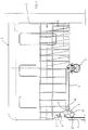
- Fig. 1 shows the upper part of the wash tub of a dishwashing machine according to the present invention.
- Said tub indicated as a whole by number 1, has an upper basket 2 with a spraying element 3 of known type and operation, being fastened to its lower side.
- Number 4 indicates a plastic tubular element, with one end hydraulically connected with the spraying element 3; the other end of the tubular element 4 has a connecting device 5, which is also formed by a substantially tubular element suitable to engage in an hydraulic intake 6 on the tub rear wall.
- Said hydraulic intake 6 is practically the outlet of a feeding tube 7 connected with a feed pump of the dishwashing machine, not shown here for simplicity's sake.
- the connecting device 5 has an intermediate body 8 with two inlets, being located vertically one above the other, on the side directed to the hydraulic intake 6, specifically an upper inlet 9 and a lower inlet 10, whereas on the opposite side the intermediate body 8 has an outlet 11 connected with the tubular element 4.
- a ball 12 either in plastic material or lighter material.
- Such a ball 12 can freely slide inside the intermediate body 11 but is hindered from passing through the inlets 9 and 10 by chokes 13A and 13B, whose diameter is smaller than the diameter of ball 12.
- the ball diameter is smaller than the diameter of the inlet 11; however, a grid indicated by number 14 is provided in correspondence with the connecting point between said outlet 11 and the connecting element 4, which hinders the ball 12 from going towards the element 4, although allowing the fluid flow.
- other solutions may be provided to hinder the ball 12 from going to the element 4, such as for instance some projections or chokes in line with the mouth of the element 4 on the outlet 11.
- Figs. 1 and 3 also show how the hydraulic intake 6 includes a part 15 practically formed by the end of the tube 7, which protrudes from the rear wall of tub 1 and has a female thread externally; onto such part 15 a ring nut 16 that has a male thread is screwed, with the eventual interposition of a seal.
- the ring nut 16 is suitable to be mechanically coupled with the inlet 9 or inlet 10, which have a section suitable to be inserted into the main hole of the ring nut 16, expressly shaped to this purpose.
- a corrugation 17 outside the inlets 9 and 10 of the intermediate body 8 is acting as a stop limit element for the mechanical coupling, i.e. for insertion of the inlet 9 or 10 of the intermediate body 8 in the intake 6.
- the connecting device 5 forms an independent module that can be obtained independently from the tubular element 4 and used in various assemblies and configurations.
- the device operates as follows.
- the inlet 10 of the connecting device 5 is positioned in a way that it can be joined with the hydraulic intake 6 by a simple thrust towards the bottom of the tub 1 exerted on the basket 2 when the latter is relocated inside the dishwashing machine.
- the ball 12 is acting as a fluid flow deflector and is suitable to change its operating position only as a function of the flow pressure itself.
- the upper track 9 of the connecting device 5 will be at the same height of the hydraulic intake 6.
- the connecting device 5 has two inlets 9 and 10 suitable to be inserted at least partially in the hydraulic intake 6 with a male-on-female mating; however, it is quite obvious that the same result can be obtained through an arrangement substantially opposed to the one described in the Figs. 1-3, i.e. with a female-on-male mating.
- FIG. 4 shows a possible variant embodiment of the present invention, where the same numbers of the previous figures are used to indicate the same components already illustrated or technically equivalent elements, by adding the index '.
- FIG. 4 shows a variant embodiment of the type of mechanical/hydraulic coupling between the hydraulic intake 6' and nets 9' and 10', according to which the inlet 9' or 10' engages around the hydraulic intake 6', which in this instance is acting as a male instead of a female, as it is in the instance of Figs. 1-3.
- the part 15' of the hydraulic intake 6' has a corrugated seal 18 instead of a threading, whose purpose is to warrant both the mechanical coupling and hydraulic sealing.
- FIGs. 1 and 2 show the instance where the end of the tubular element 4, on which the spraying element 3 is mounted, is directed downwards (in other words the sprayer 3 is at a lower height with reference to the tubular element 4; thus, for this embodiment it is obvious that when the wash pump stops the fluid available in the tubular element 4 can freely flow out through the sprayer 3).
- the end of the tubular element 4 mentioned above can be directed upwards (in which case the sprayer 3 would be at a higher height with respect to the tubular element 4). Therefore, under such a situation, when the wash pump stops there could be a fluid stagnation inside the tubular element 4, since the ball 12 would obstruct the inlet 10 and hinder its outflow.
- the ball 12 can be favorably made of a light material or anyway of a floating material.
- the ball 12 lifts up leaving the inlet 10 open up to a full drainage of the fluid from the tubular element and the sprayer.
- a dishwashing machine of the kind comprising an upper crockery basket capable of taking two different height positions, which has a commutation device to feed the upper sprayer as a function of the height position selected for the basket.
- Said device which is practically integrated in the connecting element between the hydraulic feed intake and the sprayer, comprises two optional inlets and an outlet, including flow deflecting means suitable to change and/or maintain their own operating position as a function of the pressure exerted by the wash fluid from the hydraulic intake.
- the device described above has the important feature of being easily reachable by simply withdrawing the basket from the tub, in case of maintenance operations, which may even be carried out directly by the user himself.
- the ball could be replaced by other flow deflection elements, such as floats or shutters of various forms, or rocker elements, fitted with proper motion guides and suitable to be displaced by the fluid pressure.
- flow deflection elements such as floats or shutters of various forms, or rocker elements, fitted with proper motion guides and suitable to be displaced by the fluid pressure.
- FIG. 5 show a further possible embodiment of the present invention, according to which a rocker element or shutter is provided instead of a ball; this figure shows the same numbers as the previous figures to indicate the same components already illustrated or any elements technically equivalent by adding the index ''.
- the flow deflection device comprises a rocker element or defector 12'' made of plastic material and hinged in a known manner to the body 8'' of the device 5''; the coupling between the deflector 12'' and the body 8'' may be for instance by snap-fitting.
- the deflector 12'' acts as a flow deflector and is suitable to obstruct the inlet 9'' or inlet 10'' alternatively due to the pressure exerted by the wash fluid from the hydraulic feed intake 6'', following the same procedures as previously described with reference to Figs. 1-4 without reducing the fluid throughflow section.
- the chokes leading to the inlets of the connecting device may be fitted with seals to improve the ball sealing when the washing fluid under pressure enters the connecting device.
Landscapes
- Washing And Drying Of Tableware (AREA)
- Fluid-Pressure Circuits (AREA)
- Motor Or Generator Frames (AREA)
- Lubricants (AREA)
Applications Claiming Priority (2)
| Application Number | Priority Date | Filing Date | Title |
|---|---|---|---|
| ITTO960745 | 1996-09-11 | ||
| IT96TO000745A IT1284791B1 (it) | 1996-09-11 | 1996-09-11 | Macchina lavastoviglie a circuito idraulico migliorato. |
Publications (3)
| Publication Number | Publication Date |
|---|---|
| EP0829221A2 true EP0829221A2 (de) | 1998-03-18 |
| EP0829221A3 EP0829221A3 (de) | 1998-08-12 |
| EP0829221B1 EP0829221B1 (de) | 2003-04-23 |
Family
ID=11414881
Family Applications (1)
| Application Number | Title | Priority Date | Filing Date |
|---|---|---|---|
| EP97115615A Revoked EP0829221B1 (de) | 1996-09-11 | 1997-09-09 | Geschirrspülmaschine mit verbessertem Hydraulikkreislauf |
Country Status (5)
| Country | Link |
|---|---|
| EP (1) | EP0829221B1 (de) |
| AT (1) | ATE237987T1 (de) |
| DE (1) | DE69721161T2 (de) |
| ES (1) | ES2197275T3 (de) |
| IT (1) | IT1284791B1 (de) |
Cited By (10)
| Publication number | Priority date | Publication date | Assignee | Title |
|---|---|---|---|---|
| DE19934953A1 (de) * | 1999-07-26 | 2001-02-01 | Aweco Appliance Sys Gmbh & Co | Geschirrspülmaschine |
| EP1136030A1 (de) * | 2000-03-13 | 2001-09-26 | V-Zug AG | Geschirrspüler mit verstellbarem Geschirrkorb |
| US7055537B2 (en) | 2002-06-27 | 2006-06-06 | Maytag Corporation | Bullet ended wash tube for dishwasher |
| WO2009027370A1 (de) * | 2007-08-31 | 2009-03-05 | BSH Bosch und Siemens Hausgeräte GmbH | Hydraulische kupplung eines höhenverstellbaren geschirrkorbes einer geschirrspülmaschine |
| CN101917893B (zh) * | 2007-12-31 | 2013-08-14 | 阿塞里克股份有限公司 | 洗碗机 |
| WO2014132151A1 (en) * | 2013-02-27 | 2014-09-04 | Belimed Ag | Valve unit of a rack of a washing apparatus |
| EP3040012A1 (de) | 2014-12-31 | 2016-07-06 | Indesit Company S.p.A. | Haushaltsgeschirrspülmaschine |
| EP3040011A1 (de) | 2014-12-31 | 2016-07-06 | Indesit Company S.p.A. | Haushaltsgeschirrspülmaschine |
| EP3040010A1 (de) | 2014-12-31 | 2016-07-06 | Indesit Company S.p.A. | Haushaltsgeschirrspülmaschine |
| KR20190083447A (ko) * | 2018-01-04 | 2019-07-12 | 엘지전자 주식회사 | 식기 세척기 |
Family Cites Families (5)
| Publication number | Priority date | Publication date | Assignee | Title |
|---|---|---|---|---|
| SE442703B (sv) * | 1981-11-24 | 1986-01-27 | Electrolux Ab | Kopplingsanordning for ett i en diskmaskin anordnat spolsystem |
| IT1234696B (it) * | 1989-06-06 | 1992-05-26 | Zanussi A Spa Industrie | Lavastoviglie con cesto estraibile regolabile in altezza. |
| DE9010524U1 (de) * | 1990-07-12 | 1991-11-14 | Licentia Patent-Verwaltungs-Gmbh, 6000 Frankfurt | Geschirrspülmaschine mit einem höhenverstellbaren Geschirrkorb |
| IT1282096B1 (it) * | 1996-01-29 | 1998-03-12 | Smeg Spa | Dispositivo di collegamento idraulico per cestello di lavastoviglie posizionabile a due altezze diverse |
| EP0918482B1 (de) * | 1996-07-17 | 2004-10-27 | Arcelik S.A. | Lösbare hydraulische verbindung oder flussigkeitsverteilungsventil für haushaltgeschirrspülmaschine |
-
1996
- 1996-09-11 IT IT96TO000745A patent/IT1284791B1/it active IP Right Grant
-
1997
- 1997-09-09 AT AT97115615T patent/ATE237987T1/de not_active IP Right Cessation
- 1997-09-09 DE DE69721161T patent/DE69721161T2/de not_active Revoked
- 1997-09-09 ES ES97115615T patent/ES2197275T3/es not_active Expired - Lifetime
- 1997-09-09 EP EP97115615A patent/EP0829221B1/de not_active Revoked
Cited By (12)
| Publication number | Priority date | Publication date | Assignee | Title |
|---|---|---|---|---|
| DE19934953A1 (de) * | 1999-07-26 | 2001-02-01 | Aweco Appliance Sys Gmbh & Co | Geschirrspülmaschine |
| EP1136030A1 (de) * | 2000-03-13 | 2001-09-26 | V-Zug AG | Geschirrspüler mit verstellbarem Geschirrkorb |
| US7055537B2 (en) | 2002-06-27 | 2006-06-06 | Maytag Corporation | Bullet ended wash tube for dishwasher |
| WO2009027370A1 (de) * | 2007-08-31 | 2009-03-05 | BSH Bosch und Siemens Hausgeräte GmbH | Hydraulische kupplung eines höhenverstellbaren geschirrkorbes einer geschirrspülmaschine |
| CN101790342B (zh) * | 2007-08-31 | 2012-04-11 | Bsh博世和西门子家用器具有限公司 | 洗碗机的高度可调的篮的液压连接件 |
| US8561624B2 (en) * | 2007-08-31 | 2013-10-22 | Bsh Bosch Und Siemens Hausgeraete Gmbh | Hydraulic coupling of a vertically adjustable dish basket of a dishwasher |
| CN101917893B (zh) * | 2007-12-31 | 2013-08-14 | 阿塞里克股份有限公司 | 洗碗机 |
| WO2014132151A1 (en) * | 2013-02-27 | 2014-09-04 | Belimed Ag | Valve unit of a rack of a washing apparatus |
| EP3040012A1 (de) | 2014-12-31 | 2016-07-06 | Indesit Company S.p.A. | Haushaltsgeschirrspülmaschine |
| EP3040011A1 (de) | 2014-12-31 | 2016-07-06 | Indesit Company S.p.A. | Haushaltsgeschirrspülmaschine |
| EP3040010A1 (de) | 2014-12-31 | 2016-07-06 | Indesit Company S.p.A. | Haushaltsgeschirrspülmaschine |
| KR20190083447A (ko) * | 2018-01-04 | 2019-07-12 | 엘지전자 주식회사 | 식기 세척기 |
Also Published As
| Publication number | Publication date |
|---|---|
| IT1284791B1 (it) | 1998-05-21 |
| ES2197275T3 (es) | 2004-01-01 |
| EP0829221A3 (de) | 1998-08-12 |
| DE69721161D1 (de) | 2003-05-28 |
| DE69721161T2 (de) | 2004-02-12 |
| ITTO960745A1 (it) | 1998-03-11 |
| ATE237987T1 (de) | 2003-05-15 |
| EP0829221B1 (de) | 2003-04-23 |
Similar Documents
| Publication | Publication Date | Title |
|---|---|---|
| US6612009B1 (en) | Dishwasher spray arm feed system | |
| EP0829221B1 (de) | Geschirrspülmaschine mit verbessertem Hydraulikkreislauf | |
| EP2255715B1 (de) | Haushaltswaschmaschine, insbesondere Geschirrspüler, mit einem oberen Hydraulikkreislauf | |
| US9204780B2 (en) | Siphon break apparatus configured to substantially prevent a siphon effect in a fluid conduit of a dishwasher and an associated method | |
| EP0401767B1 (de) | Geschirrspüler mit herausnehmbarem und vertikal versetzbarem Geschirrkorb | |
| ITMI960150A1 (it) | Dispositivo di collegamento idraulico per cestello di lavastoviglie posizionabile a due altezze diverse | |
| ITMI951271A1 (it) | Dispositivo per controllare il lavaggio del filtro di una macchina lavastoviglie | |
| ITMI970405A1 (it) | Dispositivo di collegamento idraulico per cestello di lavastoviglie posizionabile a due altezze diverse | |
| EP0280345B1 (de) | Vorrichtung zur Herstellung von Kaffee | |
| EP1437082A3 (de) | Geschirrspülmaschine und Vorrichtung zum Steuern des Spülwasserdurchfluss | |
| KR20050105722A (ko) | 식기 세척기의 에어 브레이크 | |
| CN216060422U (zh) | 一种清洗机 | |
| EP0772994A1 (de) | Hydaulikkreislauf für eine Geschirrspülmaschine | |
| CN216776969U (zh) | 一种清洗机 | |
| CN216776985U (zh) | 一种喷淋臂与水槽的可拆卸式装配结构及清洗机 | |
| CN215838902U (zh) | 一种清洗机 | |
| CN215838897U (zh) | 一种清洗机 | |
| CN222194932U (zh) | 一种清洗机 | |
| KR101241458B1 (ko) | 식기 세척기의 노즐 홀더 결합 구조 | |
| CN219878089U (zh) | 用于洗碗机的喷淋器 | |
| JP2904681B2 (ja) | 食器洗浄機 | |
| CN219851241U (zh) | 一种多出口连接的洗瓶机 | |
| CN218474582U (zh) | 一种清洗机 | |
| CN116195946B (zh) | 一种清洗机 | |
| CN222487310U (zh) | 清洗机的双层喷淋系统及清洗机 |
Legal Events
| Date | Code | Title | Description |
|---|---|---|---|
| PUAI | Public reference made under article 153(3) epc to a published international application that has entered the european phase |
Free format text: ORIGINAL CODE: 0009012 |
|
| AK | Designated contracting states |
Kind code of ref document: A2 Designated state(s): AT BE CH DE DK ES FI FR GB GR IE IT LI NL PT SE |
|
| PUAL | Search report despatched |
Free format text: ORIGINAL CODE: 0009013 |
|
| AK | Designated contracting states |
Kind code of ref document: A3 Designated state(s): AT BE CH DE DK ES FI FR GB GR IE IT LI LU MC NL PT SE |
|
| 17P | Request for examination filed |
Effective date: 19990212 |
|
| AKX | Designation fees paid |
Free format text: DE ES FR GB IT PT SE |
|
| RBV | Designated contracting states (corrected) |
Designated state(s): DE ES FR GB IT PT SE |
|
| RBV | Designated contracting states (corrected) |
Designated state(s): AT BE CH DE DK ES FI FR GB GR IE IT LI NL PT SE |
|
| 17Q | First examination report despatched |
Effective date: 20011119 |
|
| GRAH | Despatch of communication of intention to grant a patent |
Free format text: ORIGINAL CODE: EPIDOS IGRA |
|
| GRAH | Despatch of communication of intention to grant a patent |
Free format text: ORIGINAL CODE: EPIDOS IGRA |
|
| GRAA | (expected) grant |
Free format text: ORIGINAL CODE: 0009210 |
|
| AK | Designated contracting states |
Designated state(s): AT BE CH DE DK ES FI FR GB GR IE IT LI NL PT SE |
|
| PG25 | Lapsed in a contracting state [announced via postgrant information from national office to epo] |
Ref country code: NL Free format text: LAPSE BECAUSE OF FAILURE TO SUBMIT A TRANSLATION OF THE DESCRIPTION OR TO PAY THE FEE WITHIN THE PRESCRIBED TIME-LIMIT Effective date: 20030423 Ref country code: LI Free format text: LAPSE BECAUSE OF FAILURE TO SUBMIT A TRANSLATION OF THE DESCRIPTION OR TO PAY THE FEE WITHIN THE PRESCRIBED TIME-LIMIT Effective date: 20030423 Ref country code: FI Free format text: LAPSE BECAUSE OF FAILURE TO SUBMIT A TRANSLATION OF THE DESCRIPTION OR TO PAY THE FEE WITHIN THE PRESCRIBED TIME-LIMIT Effective date: 20030423 Ref country code: CH Free format text: LAPSE BECAUSE OF FAILURE TO SUBMIT A TRANSLATION OF THE DESCRIPTION OR TO PAY THE FEE WITHIN THE PRESCRIBED TIME-LIMIT Effective date: 20030423 Ref country code: BE Free format text: LAPSE BECAUSE OF FAILURE TO SUBMIT A TRANSLATION OF THE DESCRIPTION OR TO PAY THE FEE WITHIN THE PRESCRIBED TIME-LIMIT Effective date: 20030423 Ref country code: AT Free format text: LAPSE BECAUSE OF FAILURE TO SUBMIT A TRANSLATION OF THE DESCRIPTION OR TO PAY THE FEE WITHIN THE PRESCRIBED TIME-LIMIT Effective date: 20030423 |
|
| REG | Reference to a national code |
Ref country code: GB Ref legal event code: FG4D |
|
| REG | Reference to a national code |
Ref country code: CH Ref legal event code: EP |
|
| REF | Corresponds to: |
Ref document number: 69721161 Country of ref document: DE Date of ref document: 20030528 Kind code of ref document: P |
|
| REG | Reference to a national code |
Ref country code: IE Ref legal event code: FG4D |
|
| PG25 | Lapsed in a contracting state [announced via postgrant information from national office to epo] |
Ref country code: SE Free format text: LAPSE BECAUSE OF FAILURE TO SUBMIT A TRANSLATION OF THE DESCRIPTION OR TO PAY THE FEE WITHIN THE PRESCRIBED TIME-LIMIT Effective date: 20030723 Ref country code: PT Free format text: LAPSE BECAUSE OF FAILURE TO SUBMIT A TRANSLATION OF THE DESCRIPTION OR TO PAY THE FEE WITHIN THE PRESCRIBED TIME-LIMIT Effective date: 20030723 Ref country code: GR Free format text: LAPSE BECAUSE OF FAILURE TO SUBMIT A TRANSLATION OF THE DESCRIPTION OR TO PAY THE FEE WITHIN THE PRESCRIBED TIME-LIMIT Effective date: 20030723 Ref country code: DK Free format text: LAPSE BECAUSE OF FAILURE TO SUBMIT A TRANSLATION OF THE DESCRIPTION OR TO PAY THE FEE WITHIN THE PRESCRIBED TIME-LIMIT Effective date: 20030723 |
|
| PG25 | Lapsed in a contracting state [announced via postgrant information from national office to epo] |
Ref country code: IE Free format text: LAPSE BECAUSE OF NON-PAYMENT OF DUE FEES Effective date: 20030909 |
|
| NLV1 | Nl: lapsed or annulled due to failure to fulfill the requirements of art. 29p and 29m of the patents act | ||
| REG | Reference to a national code |
Ref country code: CH Ref legal event code: PL |
|
| REG | Reference to a national code |
Ref country code: ES Ref legal event code: FG2A Ref document number: 2197275 Country of ref document: ES Kind code of ref document: T3 |
|
| PLBQ | Unpublished change to opponent data |
Free format text: ORIGINAL CODE: EPIDOS OPPO |
|
| PLBI | Opposition filed |
Free format text: ORIGINAL CODE: 0009260 |
|
| ET | Fr: translation filed | ||
| PLAX | Notice of opposition and request to file observation + time limit sent |
Free format text: ORIGINAL CODE: EPIDOSNOBS2 |
|
| 26 | Opposition filed |
Opponent name: ARCELIK ANONIM SIRKETI Effective date: 20040122 |
|
| PLBB | Reply of patent proprietor to notice(s) of opposition received |
Free format text: ORIGINAL CODE: EPIDOSNOBS3 |
|
| REG | Reference to a national code |
Ref country code: IE Ref legal event code: MM4A |
|
| RAP2 | Party data changed (patent owner data changed or rights of a patent transferred) |
Owner name: INDESIT COMPANY S.P.A. |
|
| PLCK | Communication despatched that opposition was rejected |
Free format text: ORIGINAL CODE: EPIDOSNREJ1 |
|
| APBP | Date of receipt of notice of appeal recorded |
Free format text: ORIGINAL CODE: EPIDOSNNOA2O |
|
| APAH | Appeal reference modified |
Free format text: ORIGINAL CODE: EPIDOSCREFNO |
|
| APAH | Appeal reference modified |
Free format text: ORIGINAL CODE: EPIDOSCREFNO |
|
| APBQ | Date of receipt of statement of grounds of appeal recorded |
Free format text: ORIGINAL CODE: EPIDOSNNOA3O |
|
| PGFP | Annual fee paid to national office [announced via postgrant information from national office to epo] |
Ref country code: FR Payment date: 20060919 Year of fee payment: 10 |
|
| PGFP | Annual fee paid to national office [announced via postgrant information from national office to epo] |
Ref country code: ES Payment date: 20070907 Year of fee payment: 11 |
|
| PGFP | Annual fee paid to national office [announced via postgrant information from national office to epo] |
Ref country code: DE Payment date: 20070926 Year of fee payment: 11 |
|
| APBU | Appeal procedure closed |
Free format text: ORIGINAL CODE: EPIDOSNNOA9O |
|
| RDAF | Communication despatched that patent is revoked |
Free format text: ORIGINAL CODE: EPIDOSNREV1 |
|
| RDAG | Patent revoked |
Free format text: ORIGINAL CODE: 0009271 |
|
| STAA | Information on the status of an ep patent application or granted ep patent |
Free format text: STATUS: PATENT REVOKED |
|
| 27W | Patent revoked |
Effective date: 20071002 |
|
| GBPR | Gb: patent revoked under art. 102 of the ep convention designating the uk as contracting state |
Free format text: 20071002 |
|
| PGFP | Annual fee paid to national office [announced via postgrant information from national office to epo] |
Ref country code: GB Payment date: 20070824 Year of fee payment: 11 |
|
| PGFP | Annual fee paid to national office [announced via postgrant information from national office to epo] |
Ref country code: IT Payment date: 20070920 Year of fee payment: 11 |