EP0829281A1 - Dispositif de retenue d'une chaussure pour une fixation de ski détachable - Google Patents
Dispositif de retenue d'une chaussure pour une fixation de ski détachable Download PDFInfo
- Publication number
- EP0829281A1 EP0829281A1 EP97115296A EP97115296A EP0829281A1 EP 0829281 A1 EP0829281 A1 EP 0829281A1 EP 97115296 A EP97115296 A EP 97115296A EP 97115296 A EP97115296 A EP 97115296A EP 0829281 A1 EP0829281 A1 EP 0829281A1
- Authority
- EP
- European Patent Office
- Prior art keywords
- spring
- shoe
- shoe holder
- ski
- assembly according
- Prior art date
- Legal status (The legal status is an assumption and is not a legal conclusion. Google has not performed a legal analysis and makes no representation as to the accuracy of the status listed.)
- Granted
Links
- 230000006835 compression Effects 0.000 claims abstract description 11
- 238000007906 compression Methods 0.000 claims abstract description 11
- 230000000712 assembly Effects 0.000 claims description 4
- 238000000429 assembly Methods 0.000 claims description 4
- 230000001960 triggered effect Effects 0.000 claims description 3
- 230000005540 biological transmission Effects 0.000 claims 3
- 230000007246 mechanism Effects 0.000 abstract 4
- 238000006073 displacement reaction Methods 0.000 description 4
- 230000000694 effects Effects 0.000 description 3
- 230000003993 interaction Effects 0.000 description 3
- 230000008859 change Effects 0.000 description 2
- 241001295925 Gegenes Species 0.000 description 1
- 230000001154 acute effect Effects 0.000 description 1
- 239000011324 bead Substances 0.000 description 1
- 238000005452 bending Methods 0.000 description 1
- 238000010276 construction Methods 0.000 description 1
- 230000008878 coupling Effects 0.000 description 1
- 238000010168 coupling process Methods 0.000 description 1
- 238000005859 coupling reaction Methods 0.000 description 1
- 230000004048 modification Effects 0.000 description 1
- 238000012986 modification Methods 0.000 description 1
- 210000002105 tongue Anatomy 0.000 description 1
Images


Classifications
-
- A—HUMAN NECESSITIES
- A63—SPORTS; GAMES; AMUSEMENTS
- A63C—SKATES; SKIS; ROLLER SKATES; DESIGN OR LAYOUT OF COURTS, RINKS OR THE LIKE
- A63C9/00—Ski bindings
- A63C9/08—Ski bindings yieldable or self-releasing in the event of an accident, i.e. safety bindings
- A63C9/0805—Adjustment of the toe or heel holders; Indicators therefor
-
- A—HUMAN NECESSITIES
- A63—SPORTS; GAMES; AMUSEMENTS
- A63C—SKATES; SKIS; ROLLER SKATES; DESIGN OR LAYOUT OF COURTS, RINKS OR THE LIKE
- A63C9/00—Ski bindings
- A63C9/08—Ski bindings yieldable or self-releasing in the event of an accident, i.e. safety bindings
- A63C9/081—Ski bindings yieldable or self-releasing in the event of an accident, i.e. safety bindings with swivel sole-plate
-
- A—HUMAN NECESSITIES
- A63—SPORTS; GAMES; AMUSEMENTS
- A63C—SKATES; SKIS; ROLLER SKATES; DESIGN OR LAYOUT OF COURTS, RINKS OR THE LIKE
- A63C9/00—Ski bindings
- A63C9/08—Ski bindings yieldable or self-releasing in the event of an accident, i.e. safety bindings
- A63C9/085—Ski bindings yieldable or self-releasing in the event of an accident, i.e. safety bindings with sole hold-downs, e.g. swingable
- A63C9/08507—Ski bindings yieldable or self-releasing in the event of an accident, i.e. safety bindings with sole hold-downs, e.g. swingable with a plurality of mobile jaws
- A63C9/08521—Ski bindings yieldable or self-releasing in the event of an accident, i.e. safety bindings with sole hold-downs, e.g. swingable with a plurality of mobile jaws pivoting about a vertical axis, e.g. side release
-
- A—HUMAN NECESSITIES
- A63—SPORTS; GAMES; AMUSEMENTS
- A63C—SKATES; SKIS; ROLLER SKATES; DESIGN OR LAYOUT OF COURTS, RINKS OR THE LIKE
- A63C9/00—Ski bindings
- A63C9/08—Ski bindings yieldable or self-releasing in the event of an accident, i.e. safety bindings
- A63C9/085—Ski bindings yieldable or self-releasing in the event of an accident, i.e. safety bindings with sole hold-downs, e.g. swingable
- A63C9/08557—Details of the release mechanism
- A63C9/08564—Details of the release mechanism using cam or slide surface
-
- A—HUMAN NECESSITIES
- A63—SPORTS; GAMES; AMUSEMENTS
- A63C—SKATES; SKIS; ROLLER SKATES; DESIGN OR LAYOUT OF COURTS, RINKS OR THE LIKE
- A63C9/00—Ski bindings
- A63C9/08—Ski bindings yieldable or self-releasing in the event of an accident, i.e. safety bindings
- A63C9/085—Ski bindings yieldable or self-releasing in the event of an accident, i.e. safety bindings with sole hold-downs, e.g. swingable
- A63C9/08557—Details of the release mechanism
- A63C9/08571—Details of the release mechanism using axis and lever
-
- A—HUMAN NECESSITIES
- A63—SPORTS; GAMES; AMUSEMENTS
- A63C—SKATES; SKIS; ROLLER SKATES; DESIGN OR LAYOUT OF COURTS, RINKS OR THE LIKE
- A63C9/00—Ski bindings
- A63C9/001—Anti-friction devices
Definitions
- the invention relates to a shoe holder assembly of a releasable ski binding, in particular a shoe holder assembly for holding the toe area of a ski shoe, with a first adjustable spring assembly for controlling a release of the ski shoe in the direction of a shoe transverse axis and an adjustable support assembly or a second adjustable spring assembly for controlling a release of the ski boot towards a shoe vertical axis.
- Such shoe holder assemblies are generally known and available on the market. Such an assembly is described by way of example in DE-OS 26 29 452.
- the binding has on the one hand releasable shoe holders that hold the shoe in the lateral direction with limited force, and on the other hand a separate shoe holder that holds the ski boot against an upward movement relative to the top of the ski backs up. All of these shoe holders are held on separate leaf springs which are designed as channel profiles, the convex side pointing in the respective release direction.
- shoe holder assemblies in which shoe holders that can be released in the lateral direction and that secure the ski boot against movement in the vertical direction relative to the ski are arranged on a common housing, which is pivotally mounted about a ski cross axis, whereby a single release spring on the one hand pushes the shoe holder and on the other hand the housing into a normal position. It is advantageous here that when the spring tension of the release spring changes, both the release force in the sideways direction and the release force in the vertical direction are simultaneously changed. However, the design effort is comparatively high. In addition, the size ratio between the triggering forces in the lateral and vertical directions cannot be changed without major design changes.
- the object of the invention is therefore to show a particularly advantageous construction for a shoe holder assembly of the type specified at the outset.
- the invention is based on the general idea of providing separate units for different triggering directions and of making a simultaneous adjustment of the triggering forces assigned to the respective triggering directions or a simultaneous change in the triggering behavior in both triggering directions by means of a common actuator which controls the abutment of both units. This gives great constructive freedom with regard to the relationship between the triggering forces acting in different directions. Essentially, only the shape of the abutments and / or the coupling between the abutments and the adjusting member need to be modified.
- the first spring assembly has a helical compression spring, the compressive stress of which can be adjusted at one end of the helical compression spring by means of a spring abutment which can be adjusted in the direction of the spring axis, and that the adjusting member or the spring abutment is coupled to a lever member which has an adjustable support of a leaf spring arranged as a spring element of the second spring unit or a lever part of the support assembly.
- the helical compression spring provided for the control of a lateral release can be arranged in basically the same way as with conventional shoe holder units which can only be released in the lateral direction and that practically no additional space is required for the leaf spring or the lever part provided for controlling a release in the vertical direction .
- a shoe holder arrangement that can be triggered in the sideways direction with a certain vertical play relative to the upper side of the ski and to press this shoe holder arrangement in the direction of the upper side of the ski by means of the leaf spring or the lever part, which can also be designed as a rocker. As soon as the ski boot lifts the boot holder assembly sufficiently far against the force of the leaf spring, it is released in the upward direction.
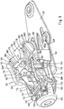
- two very stable, ski-fixed vertical axes 20 are arranged on both sides of the longitudinal axis of the ski, on which the front ends of two stable guide links 21 in the longitudinal direction of the ski are pivoted, the rear ends of which in the longitudinal direction of the ski via pivot pins 22 with one in the longitudinal direction of the ski front section of a parallel to the top of the slide plate 8 are pivotally connected.
- the top axes 20 and the pivot pins 22 form a parallelogram-like or trapezoid-like square in a plan view of the top of the ski.
- the guide links 21 or their articulated eyes penetrated by the vertical axes 20 are designed such that the guide links 21 can also be pivoted in the direction of the arrow P in FIG. 1, ie the ends of the guide links 21 remote from the vertical axes 20 can move together with the sliding plate 8 move relative to the top of the ski 1 or the base plate 4 in the upward direction.
- the guide link 21 can at their upper horizontal edges have a round hole penetrated by the respective vertical axis 20, which includes the vertical axis 20 without any significant radial play. Towards the lower horizontal edge of the respective guide link 21, said round hole widens into an elongated hole extending in the longitudinal direction of the guide link 21.
- the guide links 21 can have a C-profile in the region of the vertical axes 20 when viewed in the longitudinal direction of the ski.
- the round hole is provided in the upper C-leg and the elongated hole in the lower C-leg at the lower horizontal edge of the respective guide link 21.
- the slide plate 8 is preferably, as can be seen in particular from FIGS. 2 and 3 and 8, in two parts, a front plate part 8 'being articulated to the guide links 21 and a rear plate part 8''on the front plate part 8' by one Transverse axis 9 is pivotally arranged.
- the rear transverse edge of the rear plate part 8 ′′ is received by an extension which extends the base plate 4 and which, when viewed in the transverse direction of the ski, forms a V-profile which is open towards the tip of the ski, in a manner similar to that in a guide rail.
- a stable, upwardly projecting transverse wall 23 is formed on the front area of the front slide plate part 8 ', which has a central extension 24 pointing in the forward ski direction, which is designed as a bearing block for a roller-like roller 26 which can be rotated about an axis 25 perpendicular to the upper side of the ski.
- the roller 26 interacts with link arms 27, compare in particular FIG. 5, which are pivotally mounted on the ski-fixed vertical axes 20 in corresponding recesses on the guide links 21.
- the link arms 27 are pushed against the roller 26 by a helical compression spring 28.
- the helical compression spring 28 is supported on an abutment 30 which can be displaced in the longitudinal direction of the ski by means of the adjusting screw 29 and which in turn is supported on the front end wall of a housing firmly connected to the base plate 4 via the adjusting screw 29.
- the other end of the spring 28 is tensioned against a piston-like part 31 which, on its end facing the link arms 27, holds a pin 32 parallel to the vertical axis of the ski, by means of which the piston-like part 31 under the pressure of the helical compression spring 28 into the front end of the ski engages open recesses on the link arms 27.
- the intersecting link arms 27 form with their edges facing the sliding plate 8 a V-shaped recess which receives the roller 26 and is open towards the sliding plate 8 and seek the roller 26 and thus to bring the sliding plate 8 into a position centered on the longitudinal axis of the ski.
- the sliding plate 8 If the sliding plate 8 is subjected to greater force in the ski transverse direction, it moves transversely to the ski 1, in FIG. 5, for example, in the upward direction, one of the link arms 27 from the roller 26 and the darkly shown link arm 27 below in FIG. 5 increasing tension of the helical compression spring 28 is pivoted.
- the backdrop-shaped, cooperating with the roller 26 edges of the link arms 27 are designed such that in the vicinity of the normal position of the sliding plate 8 shown in FIG. 5, comparatively large transverse forces must act on the sliding plate 8 in order to move it sideways from the illustrated central position move. With increasing sideways displacement, the forces required for a further displacement can then become comparatively low.
- sole holders 34 are arranged above the guide links 21 (cf. in particular FIG. 4), which are connected to the transverse wall 23 in a hinge-like manner about pins 33 parallel to the ski vertical axis.
- These sole holders 34 form a two-armed lever in a plan view of the top of the ski, the lever arms projecting in the rearward direction of the ski being shaped such that they are able to grip around the edges of the front sole region of the ski boot from above, from the front and from the side.
- the sole holders 34 are urged elastically into an end position encompassing the side edges of the front sole region in the manner of pliers.
- the other arms of the sole holder 34 pointing in the forward ski direction cooperate with a locking lever 35 which is pivotably mounted on the transverse wall 23 of the sliding plate 8 about an axis 36 parallel to the vertical axis of the ski and by weak spring elements (not shown) in the normal position shown in FIG. 4 is pressed, in which two lateral extensions 35 'of the locking lever 35 lie laterally on the arms in the ski forward direction of the sole holder 34. So that the sole holder 34 is locked in the position of Fig. 4, i.e. the arms of the sole holder 34, which grip around the sole edges in the manner of pliers, cannot be spread.
- the locking lever 35 abuts against one of the vertical axes 20, whereby the locking lever 35 is pivoted so that the sole holder 34 on the side of the transverse wall 23 pointing in the direction of the sideways movement of the sliding plate 8 associated extension 35 'of the locking lever 35 is released and according to FIG. 6 with its arm serving to hold the shoe sole is able to execute an outward pivoting of the shoe sole.
- a bow-shaped lever 40 which, when viewed in the longitudinal direction of the ski, essentially has a downwardly open, right-angled U-profile, is pivotably mounted about a transverse axis 41, which in turn is arranged on the underside of the housing 3 and fastened to the housing side walls, or is stored.
- elongated holes 42 are arranged in the longitudinal direction of the legs, into which pins 43 engage, which in turn are arranged on tongue-like extensions 44 of the abutment 30 which can be screw-adjusted on the set screw 29. If the abutment 30 is displaced relative to the housing 3 in the longitudinal direction of the ski, the lever 40 pivots about its transverse axis 41.
- the bow-shaped lever 40 comprises a leaf spring 45 forming the upper side of the housing 3, which extends in a plan view of the ski essentially in the longitudinal direction of the ski and is supported with its front end on the front, the adjusting screw 29 bearing end wall of the housing 3, while in Ski longitudinal direction rear end of the leaf spring 45 rests on the upper horizontal edge of the transverse wall 23 or on continuations of this edge on the sole holders 34.
- the spring 45 lies with more or less spring force on the underside of the middle part of the bow-shaped lever 40 or with its ends on the front end wall of the housing 3 and the upper edge of the transverse wall 23 or the sole holder 34. This has the consequence that the leaf spring 45 tries to urge the transverse wall 23 and thus the sliding plate 8 against the top of the ski 1.
- the spring 45 In the area of the lever 40, the spring 45 has an arcuate curvature with a center of curvature falling into the transverse axis 41. This facilitates pivoting adjustment of the lever 40.
- a slider 46 is arranged at the rear end of the leaf spring 45, which together with the leaf spring 45 forms a T-shaped part in a plan view of the ski.
- This slide 46 lies with its underside on the upper horizontal edge of the transverse wall 23, the upper transverse edge having an M-shaped contour in the longitudinal view of FIG. 8, while the underside of the slide 46 is W-shaped.
- the underside of the slide 46 is W-shaped.
- the underside of the sliding plate part 8 ′′ and a cooperating area 4 ′ on the top side of the base plate 4 have a similar design.
- the shoe holder assembly shown functions as follows: Normally, the front area of the shoe sole 5 of the ski shoe is gripped like a pair of pliers by the sole holders 34 in the position shown in FIG. 4, the sole holders 34 also overlapping the sole edge from above. If greater transverse forces should now act on the ski shoe relative to the ski 1, for example if the skier falls, the front sole part 5 of the ski shoe presses against one of the sole holders 34, with the result that, with a sufficiently large transverse force, the slide plate 8 together with the sole holders 34 is moved sideways relative to the ski.
- the sole holders 34 initially remain in their locked position, ie the sole holders 34 have the position shown in FIG. 4 relative to the sliding plate 8.
- the resistance which must be overcome during this sideways movement is determined by the compressive stress of the helical compression spring 28 and the shape of the link arms 27 interacting with the roller 26. If the transverse force acting on the ski boot is maintained, the sliding plate 8 with the sole holders 34 is moved so far in the transverse direction that the locking lever 35 strikes one of the vertical axes 20 and reaches a pivoting position according to FIG. 6, with the result that the in Direction of transverse displacement of the slide plate 8 front sole holder 34 - in FIG. 6 the upper sole holder 34 - is completely unlocked and is pivoted open by the shoe which is still pushed sideways according to FIG. 6. This triggers the ski boot sideways, ie releases it.
- the slide plate 8 executes a pivoting about a vertical axis of the ski in such a way that the longitudinal axis S and the longitudinal axis G of the sliding plate 8 form an acute angle opened in the ski forward direction and only slight relative movements occur between the shoe sole and the sliding plate 8.
- the ramps arranged next to the cusps have the effect that the pressure on the sliding plate part increases 8 'against the base plate 4 an increasing force component occurs in the sideways direction, ie the sideways movement of the slide plate 8 is supported by this force component.
- the mutually interacting sliding surfaces on the sliding piece 46 and on the transverse wall 23 on the one hand and on the slide plate 8 and the base plate 4, on the other hand be designed such that in the event of a backward turn or a forward turn, the friction-increasing effect of the forces acting in the upward or downward direction on the shoe is more than compensated.
- This can ensure that the triggering forces in the sideways direction in the case of so-called combined falls - forward lintel or backward lintel - are lower than with disturbing forces acting exclusively on the shoe in the lateral direction.
- the leaf spring 45 can also be formed in the region of the lever 40 without the curvature according to FIG. 2.
- a slider or molded part with a corresponding curvature can be arranged on the leaf spring 45.
- the leaf spring 45 may have a fixed abutment instead of the lever 40 at its central region and be mounted with its end region on the left in FIG. 2 on the displaceable abutment 30 or a supporting part firmly connected to it. In this case too, the trigger force determined by the leaf spring 45 in the event of a backward fall is changed by adjusting the abutment 30.
- a base plate 101 fixedly arranged on the upper side of a ski (not shown) carries a skeleton-like housing structure 102 firmly connected to it.
- two guide links 103 are pivotally mounted on both sides of a vertical central longitudinal plane, whereby it is ensured by bearing play that the guide links 103 are also somewhat pivotable about a transverse axis passing through their housing-side bearing parts.
- the guide links 103 each carry two vertically approximately superimposed hinge eyes 103 ', which serve to support sole holder parts 104, which are only indicated in FIG. 10 and which, in their normal position, grip around the front end of the sole and thus hold it in the transverse direction.
- the guide links 103 are articulated to one another at their upper hinge eyes 103 'via a flat band 105, so that they always pivot together in the transverse direction.
- the guide links 103 are deflected in the direction of the viewer.
- a sole holder part 106 Arranged on the flat belt 105 is a sole holder part 106 which overlaps the front sole edge from above and engages around the front transverse edge of the flat belt 105 with hook-like projections 106 'with which the sole holder part 106 is held so that it can be pivoted up around the front edge of the flat belt 105.
- the rear transverse edge of the sole holder part 106 is designed as a downward-facing last 107 which projects downward from the underside of the flat belt 105 in the normal position of the sole holder part 106 and rests on the edge of the front sole end of the ski boot from above.
- two strip-like prism bodies 108 are formed, which are oriented somewhat obliquely to the longitudinal axis of the ski or the shoe holder assembly, such that the longitudinal directions of the prism bodies 108 form an angle that opens slightly towards the rear end of the ski.
- the backs of the prism bodies 108 each have a narrow median strip without a sideways inclination, inclined surfaces 108 'adjoining them on both sides with a slight sideways gradient of, for example, 8 ° and adjoining flanks 108' 'with a steep gradient of, for example, 50 ° the horizontal.
- the housing structure 102 has a stiffening part 109 which is arranged between the guide links 103 and which is provided with Feet 109 ', which serve as pivot axes of the guide links 103, are held on an underside of the housing and are held on an essentially horizontal upper part 109''on two stable housing columns 110. Laterally outside of the columns 110, two beads 111 are formed on the upper part 109 ′′ with the convex side pointing downward.
- the housing structure 102 forms a longitudinal guide for a spring abutment 112, which is displaceable and adjustable in the longitudinal direction in a generally known manner by means of an adjusting screw, not shown, which is held by a receiving part 113.
- This spring abutment 112 supports a helical compression spring, which is arranged in the longitudinal direction and is not shown, which controls a basically known latching arrangement with which the guide links 103 are held in a central position which can be triggered in the sideways direction.
- a spring part 115 is fixed to the columns 110 in the longitudinal and transverse directions of the shoe holder assembly.
- This spring part has a top view in the area of the columns and of the upper part 109 ′′ of the stiffening part 109 has an H-shaped shape, the H crosspiece being arranged in the longitudinal direction behind the upper part 109 ′′.
- the rearward-facing ends of the H side parts interact with the prism bodies 108 of the sole holder part 106 in a manner shown below.
- the H-side parts are angled vertically downwards, the downwardly angled parts being provided with shoulders 116 which cooperate with the upper edges 114 ′ of the extensions 114 in a manner shown further below.
- the H-side parts are designed in the manner of spring tongues with spring brackets 115 'which extend forwards in the forward direction and which are connected to one another between the extensions 114 by a cross bracket 117.
- extensions 118 aligned in the longitudinal direction are connected, which are supported on the spring abutment 112 between the extensions 114 and shoulders 112 'without hindering the adjustability of the spring abutment 112.
- the spring clips 115 'between the shoulders 116 and the cross clip 117 are resilient in the manner of leaf springs, while the regions of the spring part 115 adjoining them upwards and backwards are comparatively rigid, since here the side parts of the spring part 115 laterally bent edges 115 '' and accordingly have a channel profile.
- the rearward-facing ends of the spring part 115 form prism bodies 119 similar to the prime bodies 108 of the sole holder part 106, with a narrow central surface arranged in the transverse direction without inclination connecting flat upward inclined surfaces and steep upward inclined flanks thereon.
- the outer flanks merge into the edges 115 ′′; the inner flanks are rigidly connected to one another via a raised edge of the transverse web of the spring parts 115 next to the upper part 109 ′′.
- the guide links 103 and the sole holder part 106 assume their central position, in which the sole holder parts 104 encompass the lateral sole edges and the sole holder 106 with its last 107 the front edge of the The sole overlaps from above.
- the sole holder part 106 lies with its prism bodies 108 on the prism bodies 119, in such a way that the narrow central regions of the prism bodies, ie theirs Rooftops ", stand on each other.
- the shoe sole presses against one of the side sole holder parts 104, with the result that the guide links 103 are deflected against a restoring force generated by the release spring. If the deflection is sufficiently wide, the sole holder part 104 located at the front in the direction of movement swings outward and releases the shoe.
- the shoe holder assembly according to the invention functions in a conventional manner.
- the sole holder part 106 is urged upwards against the prism body 119, the sole holder part 106 trying to pivot about the front transverse edge of the flat band 105 encompassed by its hook-like extensions 106 '(in FIG 9 counterclockwise).
- the prism body 119 of the spring part 115 can be bent up such that the sole holder part 106 releases the sole edge overlapped by it and thus the shoe sole and the shoe upwards.
- the spring force of the spring clips 115 ' must be overcome.
- the spring part 115 is supported sooner or later with its shoulders 116 on the upper edges 114 'of the extensions 114, so that the region of the spring part 115 stiffened by the edges 115''is more or less elastically bent.
- the forces to be overcome are determined by the position of the spring abutment 112 and the extensions 114 connected to it. If the spring abutment 112 in Fig. 9 with the extensions 114 is shifted far to the right, the prism bodies 119 form a particularly rigid abutment for the prism bodies 108 of the sole holder part 106. On the other hand, if the spring abutment 112 in FIG. 9 is moved to the left together with the extensions 114, the prism bodies 119 are held comparatively resiliently.
- the guide links 103 will pivot somewhat to the side, so that the prism body 108 of the sole holder part 106 and the prism body 119 of the spring part 115 from the position shown in image A in FIG. 13, in which the Rooftops "of the prism bodies 108 and 119 lie one on top of the other, get into the position of the image B in FIG. 13, in which the prism bodies 108 and 119 lie somewhat eccentrically on one another, ie theirs inclined flat surfaces on the sides of their median strips or their rooftops interact with each other.
- the sole holder part 106 receives increasing mobility in the upward direction with increasing sideways movement and can finally release the shoe upwards.
- a force pushing the sole holder part 106 upwards by the interaction of the flanks of the prism bodies 108 and 119 with one another, supports an increasing sideways pivoting of the guide links 103, since the upward force generates a sideways force acting on the guide links which counteracts the release resistance which counteracts sideways release of the binding the binding counteracts with the result that the shoe or sole is ultimately released more easily in the sideways direction with continued upward force.
- FIG. 9 shows the sole holder 106 in a position in which the prism bodies 108 are displaced relative to the prism bodies 119 in the direction of the viewer and the sole holder 106 together with the ends of the guide links 103 holding it or with the flat band 105 one in the upward direction have reached elevated position.
- FIG. 14 shows a modification of the embodiment shown in FIG. 1.
- the embodiment of FIG. 14 differs from the embodiment of FIG. 1 essentially in that the leaf spring 45 of FIG. 1 in 14 is replaced by a comparatively rigid lever part 245, which is supported with its left end in FIG. 14 on a fixed part of the housing 3 or essentially ski-like manner and is covered in its central area on its upper side by the lever member 40, such that the slider 46 located at the right end of the lever member 245 is held against major upward movement.
- the lever member 40 can cover a curvature on the top of the lever part 245, this curvature can be shaped such that the pivot member 46 is pushed somewhat in the downward direction when the lever member 40 is pivoted clockwise.
- the leaf spring part 115 of FIG. 11 is replaced by a relatively stiff rocker 215, which is held on the housing-fixed columns 110 and can be tilted about a ski transverse axis, the left end of which in FIG. 15 on the spring abutment 112 against vertical movement is supported downwards.
- the other end of the rocker 215 is formed by the prism bodies 119, which interact with the prism bodies 108.
- the side of the rocker 215 cooperating with the spring abutment 112 for supporting the rocker 215 can be designed as an inclined or curved surface such that any play between the abutment 112 and the rocker 215 is increasingly reduced when the spring abutment 112 is moved to the right and / or the seesaw 215 with the prism bodies 119 is increasingly clamped against the prism bodies 108.
- the lateral forces which are generated by the interaction of the prism bodies 119 and 108, also change when these prism bodies are deflected relative to one another from the central position shown in the illustration A in FIG. 13, because the illustrations B and C in FIG. 13, because apply greater lateral forces to the respective ski boot.
- the lever part 245 or the rocker 215 can be designed as plastic parts or as parts of a binding housing.
Landscapes
- Footwear And Its Accessory, Manufacturing Method And Apparatuses (AREA)
Applications Claiming Priority (2)
| Application Number | Priority Date | Filing Date | Title |
|---|---|---|---|
| DE19636886 | 1996-09-11 | ||
| DE19636886A DE19636886A1 (de) | 1996-09-11 | 1996-09-11 | Schuhhalteraggregat einer auslösbaren Skibindung |
Publications (2)
| Publication Number | Publication Date |
|---|---|
| EP0829281A1 true EP0829281A1 (fr) | 1998-03-18 |
| EP0829281B1 EP0829281B1 (fr) | 2003-03-19 |
Family
ID=7805243
Family Applications (1)
| Application Number | Title | Priority Date | Filing Date |
|---|---|---|---|
| EP97115296A Expired - Lifetime EP0829281B1 (fr) | 1996-09-11 | 1997-09-04 | Dispositif de retenue d'une chaussure pour une fixation de ski détachable |
Country Status (4)
| Country | Link |
|---|---|
| US (1) | US5997026A (fr) |
| EP (1) | EP0829281B1 (fr) |
| AT (1) | ATE234650T1 (fr) |
| DE (2) | DE19636886A1 (fr) |
Cited By (1)
| Publication number | Priority date | Publication date | Assignee | Title |
|---|---|---|---|---|
| WO1999061118A1 (fr) * | 1998-05-22 | 1999-12-02 | Marker Deutschland Gmbh | Fixation de ski |
Families Citing this family (10)
| Publication number | Priority date | Publication date | Assignee | Title |
|---|---|---|---|---|
| FR2769236B1 (fr) * | 1997-10-03 | 2000-02-04 | Salomon Sa | Cale d'amortissement pour dispositif de retenue d'une chaussure sur une planche de glisse destinee a la pratique du surf sur neige, et dispositif muni d'une telle cale |
| FR2806639B1 (fr) * | 2000-03-23 | 2002-06-21 | Emery Sa | Perfectionnement pour dispositif de retenue d'une chaussure de ski sur un ski |
| FR2808454B1 (fr) * | 2000-05-04 | 2002-08-02 | Salomon Sa | Element de retenue de l'avant d'une chaussure sur un ski |
| DE10024384A1 (de) * | 2000-05-17 | 2001-11-29 | Mack Gerd R | Herstellung von dendritischen Zellen aus Rückenmarkstammzellen |
| US6877759B2 (en) * | 2002-08-27 | 2005-04-12 | Louis Dandurand | Ski binding |
| DE102006039989B4 (de) * | 2006-08-25 | 2015-10-08 | Marker Deutschland Gmbh | Schuhhalteraggregat einer Skibindung |
| FR2927818B1 (fr) * | 2008-02-26 | 2011-09-09 | Salomon Sa | Dispositif de declenchement pour fixation d'une chaussure sur un engin de glisse |
| AT506526B1 (de) * | 2008-02-29 | 2012-07-15 | Atomic Austria Gmbh | Vorderbacken einer sicherheitsschibindung |
| DE102011009118B4 (de) | 2011-01-21 | 2022-03-17 | Marker Deutschland Gmbh | Skibindung für Skischuhe unterschiedlicher Art |
| FR2993470B1 (fr) * | 2012-07-19 | 2015-05-29 | Salomon Sas | Dispositifs de retenue avant d'une planche de glisse |
Citations (3)
| Publication number | Priority date | Publication date | Assignee | Title |
|---|---|---|---|---|
| CH511039A (fr) * | 1969-06-10 | 1971-08-15 | Salomon Georges P J | Fixation de sécurité pour ski |
| AT353145B (de) * | 1974-06-20 | 1979-10-25 | Ver Baubeschlag Gretsch Co | Sicherheitsskibindung |
| EP0480328A1 (fr) * | 1990-10-09 | 1992-04-15 | NORDICA S.p.A | Fixation de ski |
Family Cites Families (10)
| Publication number | Priority date | Publication date | Assignee | Title |
|---|---|---|---|---|
| DE2629452A1 (de) * | 1976-06-30 | 1978-01-05 | Walter Manfreda | Schibindung |
| DE2802775C2 (de) * | 1978-01-23 | 1981-10-15 | Geze Gmbh, 7250 Leonberg | Sicherheitsskibindung mit einem um eine Querachse schwenkbaren Gehäuse |
| DE3403472A1 (de) * | 1984-02-01 | 1985-08-08 | Marker Patentverwertungsgesellschaft mbH, Baar | Vorderbacken fuer sicherheits-skibindungen |
| CH673403A5 (en) * | 1987-12-23 | 1990-03-15 | Marker Deutschland Gmbh | Front jaw for ski-binding - has two supporting members for flat w-shaped pedal and are spaced apart for distance corresponding to amount of elastic movement |
| FR2640516B1 (fr) * | 1988-12-16 | 1991-03-29 | Salomon Sa | Fixation de securite pour ski destinee a maintenir, de facon declenchable, l'avant d'une chaussure montee sur le ski |
| DE4023569A1 (de) * | 1990-07-25 | 1992-01-30 | Salem Francis Gnanapragasam | Bohrer - schleifgeraet |
| FR2672507B1 (fr) * | 1991-02-12 | 1993-06-04 | Salomon Sa | Butee-avant de securite pour fixation de ski. |
| DE4203569A1 (de) * | 1992-02-07 | 1993-08-12 | Look Sa | Sicherheitsvorderbacken einer skibindung |
| AT399102B (de) * | 1993-02-15 | 1995-03-27 | Tyrolia Freizeitgeraete | Sicherheitsbindung |
| FR2718048B1 (fr) * | 1994-03-30 | 1996-05-31 | Salomon Sa | Elément et ensemble de retenue d'une chaussure sur une planche de glisse. |
-
1996
- 1996-09-11 DE DE19636886A patent/DE19636886A1/de not_active Withdrawn
-
1997
- 1997-09-04 DE DE59709546T patent/DE59709546D1/de not_active Expired - Lifetime
- 1997-09-04 EP EP97115296A patent/EP0829281B1/fr not_active Expired - Lifetime
- 1997-09-04 AT AT97115296T patent/ATE234650T1/de not_active IP Right Cessation
- 1997-09-05 US US08/927,127 patent/US5997026A/en not_active Expired - Fee Related
Patent Citations (3)
| Publication number | Priority date | Publication date | Assignee | Title |
|---|---|---|---|---|
| CH511039A (fr) * | 1969-06-10 | 1971-08-15 | Salomon Georges P J | Fixation de sécurité pour ski |
| AT353145B (de) * | 1974-06-20 | 1979-10-25 | Ver Baubeschlag Gretsch Co | Sicherheitsskibindung |
| EP0480328A1 (fr) * | 1990-10-09 | 1992-04-15 | NORDICA S.p.A | Fixation de ski |
Cited By (1)
| Publication number | Priority date | Publication date | Assignee | Title |
|---|---|---|---|---|
| WO1999061118A1 (fr) * | 1998-05-22 | 1999-12-02 | Marker Deutschland Gmbh | Fixation de ski |
Also Published As
| Publication number | Publication date |
|---|---|
| ATE234650T1 (de) | 2003-04-15 |
| DE19636886A1 (de) | 1998-03-12 |
| DE59709546D1 (de) | 2003-04-24 |
| EP0829281B1 (fr) | 2003-03-19 |
| US5997026A (en) | 1999-12-07 |
Similar Documents
| Publication | Publication Date | Title |
|---|---|---|
| EP0778055B1 (fr) | Fixation pour snowboard | |
| AT397923B (de) | Sicherheitsskibindung | |
| DE202009019128U1 (de) | Zeheneinheit für Tourenskibindung | |
| DE202012002705U1 (de) | Ferseneinheit für eine Tourenbindung | |
| EP3928842B1 (fr) | Unité avant pour une fixation de randonnée | |
| EP0829281A1 (fr) | Dispositif de retenue d'une chaussure pour une fixation de ski détachable | |
| EP1385585A1 (fr) | Fixation de ski | |
| DE3515847A1 (de) | Seitenbacken-verriegelung | |
| DE69401171T2 (de) | Bindungselement für einen alpinen Ski | |
| DE3405861C2 (de) | Langlauf- bzw. Wanderbindung | |
| EP1428559B1 (fr) | Fixation déclenchable | |
| EP1586354A1 (fr) | Fixation de ski de Telemark ou de ski de fond ,ainsi que ses chaussures adaptés | |
| DE3151162A1 (de) | Ausloeseskibindung | |
| DE69400106T2 (de) | Bindungselement für einen alphinen Ski | |
| EP0829282B1 (fr) | Support de chaussure d'un fixation de ski déclenchable | |
| EP1795236B1 (fr) | Fixation de ski | |
| EP0443108B1 (fr) | Fixation de sécurité de ski à déclenchement intégrée aux chaussures de ski | |
| DE4424737C1 (de) | Snowboardbindung | |
| DE2528578A1 (de) | Sicherheitsbindung fuer skischuhe | |
| EP0951926B1 (fr) | Fixation de ski de randonnée, de ski de Telemark ou de ski de fond | |
| DE69602509T2 (de) | Schuhrückhaltevorrichtung auf einem Snowboard bzw. Ski oder ähnlichem | |
| DE69707932T2 (de) | Bindungssystem für Schuhe auf Skis | |
| DE3421499A1 (de) | Sicherheitsskibindung | |
| EP0354482A2 (fr) | Fixation de sécurité de ski | |
| AT510021B1 (de) | Sohlenauflageplatte und skibindung mit einer sohlenauflageplatte |
Legal Events
| Date | Code | Title | Description |
|---|---|---|---|
| PUAI | Public reference made under article 153(3) epc to a published international application that has entered the european phase |
Free format text: ORIGINAL CODE: 0009012 |
|
| AK | Designated contracting states |
Kind code of ref document: A1 Designated state(s): AT CH DE FR IT LI |
|
| 17P | Request for examination filed |
Effective date: 19980724 |
|
| AKX | Designation fees paid |
Free format text: AT CH DE FR IT LI |
|
| RBV | Designated contracting states (corrected) |
Designated state(s): AT CH DE FR IT LI |
|
| GRAH | Despatch of communication of intention to grant a patent |
Free format text: ORIGINAL CODE: EPIDOS IGRA |
|
| GRAH | Despatch of communication of intention to grant a patent |
Free format text: ORIGINAL CODE: EPIDOS IGRA |
|
| GRAA | (expected) grant |
Free format text: ORIGINAL CODE: 0009210 |
|
| AK | Designated contracting states |
Designated state(s): AT CH DE FR IT LI |
|
| REG | Reference to a national code |
Ref country code: CH Ref legal event code: EP |
|
| REF | Corresponds to: |
Ref document number: 59709546 Country of ref document: DE Date of ref document: 20030424 Kind code of ref document: P |
|
| ET | Fr: translation filed | ||
| PLBE | No opposition filed within time limit |
Free format text: ORIGINAL CODE: 0009261 |
|
| STAA | Information on the status of an ep patent application or granted ep patent |
Free format text: STATUS: NO OPPOSITION FILED WITHIN TIME LIMIT |
|
| 26N | No opposition filed |
Effective date: 20031222 |
|
| PGFP | Annual fee paid to national office [announced via postgrant information from national office to epo] |
Ref country code: CH Payment date: 20070925 Year of fee payment: 11 Ref country code: AT Payment date: 20070926 Year of fee payment: 11 |
|
| PGFP | Annual fee paid to national office [announced via postgrant information from national office to epo] |
Ref country code: IT Payment date: 20070919 Year of fee payment: 11 |
|
| PGFP | Annual fee paid to national office [announced via postgrant information from national office to epo] |
Ref country code: FR Payment date: 20070920 Year of fee payment: 11 |
|
| REG | Reference to a national code |
Ref country code: CH Ref legal event code: PL |
|
| REG | Reference to a national code |
Ref country code: FR Ref legal event code: ST Effective date: 20090529 |
|
| PG25 | Lapsed in a contracting state [announced via postgrant information from national office to epo] |
Ref country code: IT Free format text: LAPSE BECAUSE OF NON-PAYMENT OF DUE FEES Effective date: 20080904 Ref country code: AT Free format text: LAPSE BECAUSE OF NON-PAYMENT OF DUE FEES Effective date: 20080904 |
|
| PG25 | Lapsed in a contracting state [announced via postgrant information from national office to epo] |
Ref country code: LI Free format text: LAPSE BECAUSE OF NON-PAYMENT OF DUE FEES Effective date: 20080930 Ref country code: FR Free format text: LAPSE BECAUSE OF NON-PAYMENT OF DUE FEES Effective date: 20080930 Ref country code: CH Free format text: LAPSE BECAUSE OF NON-PAYMENT OF DUE FEES Effective date: 20080930 |
|
| PGFP | Annual fee paid to national office [announced via postgrant information from national office to epo] |
Ref country code: DE Payment date: 20121102 Year of fee payment: 16 |
|
| REG | Reference to a national code |
Ref country code: DE Ref legal event code: R119 Ref document number: 59709546 Country of ref document: DE Effective date: 20140401 |
|
| PG25 | Lapsed in a contracting state [announced via postgrant information from national office to epo] |
Ref country code: DE Free format text: LAPSE BECAUSE OF NON-PAYMENT OF DUE FEES Effective date: 20140401 |