EP0829281B1 - Schuhhalteraggregat einer auslösbaren Skibindung - Google Patents
Schuhhalteraggregat einer auslösbaren Skibindung Download PDFInfo
- Publication number
- EP0829281B1 EP0829281B1 EP97115296A EP97115296A EP0829281B1 EP 0829281 B1 EP0829281 B1 EP 0829281B1 EP 97115296 A EP97115296 A EP 97115296A EP 97115296 A EP97115296 A EP 97115296A EP 0829281 B1 EP0829281 B1 EP 0829281B1
- Authority
- EP
- European Patent Office
- Prior art keywords
- boot
- spring
- ski
- retaining
- holder
- Prior art date
- Legal status (The legal status is an assumption and is not a legal conclusion. Google has not performed a legal analysis and makes no representation as to the accuracy of the status listed.)
- Expired - Lifetime
Links
- 230000006835 compression Effects 0.000 claims abstract description 11
- 238000007906 compression Methods 0.000 claims abstract description 11
- 230000007246 mechanism Effects 0.000 abstract 4
- 230000008859 change Effects 0.000 description 3
- 238000006073 displacement reaction Methods 0.000 description 3
- 230000000694 effects Effects 0.000 description 3
- 230000001960 triggered effect Effects 0.000 description 3
- 241001295925 Gegenes Species 0.000 description 2
- 230000003993 interaction Effects 0.000 description 2
- 230000001154 acute effect Effects 0.000 description 1
- 239000011324 bead Substances 0.000 description 1
- 238000005452 bending Methods 0.000 description 1
- 210000001520 comb Anatomy 0.000 description 1
- 238000010276 construction Methods 0.000 description 1
- 230000008878 coupling Effects 0.000 description 1
- 238000010168 coupling process Methods 0.000 description 1
- 238000005859 coupling reaction Methods 0.000 description 1
- 108010036922 cytoplasmic linker protein 115 Proteins 0.000 description 1
- 230000004048 modification Effects 0.000 description 1
- 238000012986 modification Methods 0.000 description 1
- 210000000056 organ Anatomy 0.000 description 1
- 230000000149 penetrating effect Effects 0.000 description 1
- 230000002093 peripheral effect Effects 0.000 description 1
Images


Classifications
-
- A—HUMAN NECESSITIES
- A63—SPORTS; GAMES; AMUSEMENTS
- A63C—SKATES; SKIS; ROLLER SKATES; DESIGN OR LAYOUT OF COURTS, RINKS OR THE LIKE
- A63C9/00—Ski bindings
- A63C9/08—Ski bindings yieldable or self-releasing in the event of an accident, i.e. safety bindings
- A63C9/0805—Adjustment of the toe or heel holders; Indicators therefor
-
- A—HUMAN NECESSITIES
- A63—SPORTS; GAMES; AMUSEMENTS
- A63C—SKATES; SKIS; ROLLER SKATES; DESIGN OR LAYOUT OF COURTS, RINKS OR THE LIKE
- A63C9/00—Ski bindings
- A63C9/08—Ski bindings yieldable or self-releasing in the event of an accident, i.e. safety bindings
- A63C9/081—Ski bindings yieldable or self-releasing in the event of an accident, i.e. safety bindings with swivel sole-plate
-
- A—HUMAN NECESSITIES
- A63—SPORTS; GAMES; AMUSEMENTS
- A63C—SKATES; SKIS; ROLLER SKATES; DESIGN OR LAYOUT OF COURTS, RINKS OR THE LIKE
- A63C9/00—Ski bindings
- A63C9/08—Ski bindings yieldable or self-releasing in the event of an accident, i.e. safety bindings
- A63C9/085—Ski bindings yieldable or self-releasing in the event of an accident, i.e. safety bindings with sole hold-downs, e.g. swingable
- A63C9/08507—Ski bindings yieldable or self-releasing in the event of an accident, i.e. safety bindings with sole hold-downs, e.g. swingable with a plurality of mobile jaws
- A63C9/08521—Ski bindings yieldable or self-releasing in the event of an accident, i.e. safety bindings with sole hold-downs, e.g. swingable with a plurality of mobile jaws pivoting about a vertical axis, e.g. side release
-
- A—HUMAN NECESSITIES
- A63—SPORTS; GAMES; AMUSEMENTS
- A63C—SKATES; SKIS; ROLLER SKATES; DESIGN OR LAYOUT OF COURTS, RINKS OR THE LIKE
- A63C9/00—Ski bindings
- A63C9/08—Ski bindings yieldable or self-releasing in the event of an accident, i.e. safety bindings
- A63C9/085—Ski bindings yieldable or self-releasing in the event of an accident, i.e. safety bindings with sole hold-downs, e.g. swingable
- A63C9/08557—Details of the release mechanism
- A63C9/08564—Details of the release mechanism using cam or slide surface
-
- A—HUMAN NECESSITIES
- A63—SPORTS; GAMES; AMUSEMENTS
- A63C—SKATES; SKIS; ROLLER SKATES; DESIGN OR LAYOUT OF COURTS, RINKS OR THE LIKE
- A63C9/00—Ski bindings
- A63C9/08—Ski bindings yieldable or self-releasing in the event of an accident, i.e. safety bindings
- A63C9/085—Ski bindings yieldable or self-releasing in the event of an accident, i.e. safety bindings with sole hold-downs, e.g. swingable
- A63C9/08557—Details of the release mechanism
- A63C9/08571—Details of the release mechanism using axis and lever
-
- A—HUMAN NECESSITIES
- A63—SPORTS; GAMES; AMUSEMENTS
- A63C—SKATES; SKIS; ROLLER SKATES; DESIGN OR LAYOUT OF COURTS, RINKS OR THE LIKE
- A63C9/00—Ski bindings
- A63C9/001—Anti-friction devices
Definitions
- the invention relates to a shoe holder assembly of a triggerable Ski binding, in particular shoe holder assembly for mounting the toe area of a ski boot, with one for Release of the ski boot in its sideways and upward direction movable shoe holder assembly.
- the CH 511 039 A shows various such aggregates, at which the trigger resistance in the lateral and upward direction Can be changed simultaneously by adjusting a single actuator is.
- Example is one about a transverse axis and a vertical axis swiveling shoe holder provided. This owns a first release spring, through which the release in the upward direction is controlled, and a second trigger spring, which determines the release force in the sideways direction.
- the spring force is a set screw that one slide acting directly on the first trigger spring adjusted.
- This slide has an inclined surface on which there is another slider, which accordingly Displacement of the first-mentioned slide a spring force the second spring performs changing stroke movement.
- EP 0 480 328 A1 relates to a binding arrangement in which the triggering behavior of a single actuator heel-side binding part and a toe-side binding part is changeable.
- This publication uses a set screw to make the spring abutment a first release spring adjusts the upward release of the heel-side binding part determined.
- the aforementioned set screw has a circumferential toothing, the one with the peripheral toothing of another screw combs.
- This additional screw is used to adjust the Tension another spring, which is connected to a rod with a Coupled cam part of the toe-side binding part is and thus the triggering forces of this toe-side binding part determined in the upward and sideways direction by the cam part on the one hand a swiveling of the toe-side Shoe holder around a transverse axis and on the other hand around one counteracts vertical vertical axis.
- DE-OS 26 29 452 is another shoe holder assembly of the type specified at the outset.
- the Binding on the one hand releasable shoe holder that holds the shoe in Hold sideways with limited force, and on the other hand a separate shoe holder, which the Ski boot relative to the top of the ski against upward movement guaranteed. All of these shoe holders are on separate Leaf springs supported, which are designed as channel profiles are, with the convex side in the respective release direction has.
- the object of the invention is therefore for a shoe holder assembly a particularly advantageous of the type specified at the outset To show construction.
- the invention is based on the general idea for different Trigger directions to provide separate units and a simultaneous adjustment of the respective trigger directions assigned trigger forces or a simultaneous Change in trigger behavior in both directions by a common actuator, which abutment controls both units. It will be a great constructive Freedom in the relationship between the effective release forces in different directions. Essentially only the shape of the abutment is needed and / or the coupling between the abutments and the adjusting member to be modified.
- the first spring assembly is a helical compression spring has, the compressive stress by means of the Adjusting element in the direction of the spring axis adjustable spring abutment adjustable at one end of the helical compression spring and that the adjusting member or the spring abutment is coupled with a lever organ, which is an adjustable Support one as a spring element of the second spring unit arranged leaf spring or a lever part of the support assembly.
- a lever organ which is an adjustable Support one as a spring element of the second spring unit arranged leaf spring or a lever part of the support assembly.
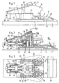
- ski-proof vertical axes 20 On one of the top of a ski Base plate 4 are two on both sides of the longitudinal axis of the ski stable, ski-proof vertical axes 20 arranged, on which the in Ski longitudinal direction front ends of two stable guide links 21 are pivoted, the rear in the longitudinal direction Ends via pivot pins 22 with one in the longitudinal direction of the ski front section of a parallel to the top of the ski Slide plate 8 are pivotally connected.
- the high axes 20 and the pivot pins 22 form a top view of the top of the ski a parallelogram or trapezoidal square.
- the guide links 21 or those of the vertical axes 20 articulated eyes are designed so that the guide links 21 also in the direction of arrow P in FIG. 1 are pivotable, i.e. those removed from the vertical axes 20 Ends of the guide link 21 can be together with the slide plate 8 relative to the top of the ski 1 or the Move base plate 4 in the upward direction.
- To the bottom horizontal edge of each Guide link 21 extends the round hole mentioned to one extending in the longitudinal direction of the guide link 21 Long hole. This is the aforementioned vertical mobility the ends connected to the slide plate 8 Guide link 21 guaranteed.
- the Guide link 21 seen in the longitudinal direction of the ski in the area of Vertical axes 20 have a C-profile. In this case it is the round hole in the upper C-leg and in the lower C-leg at the lower horizontal edge of the respective guide link 21 the slot provided.
- the sliding plate 8 is preferably, as in particular from the Figures 2 and 3 and 8 can be seen, formed in two parts, a front plate part 8 'with the guide links 21 is articulated and a rear plate part 8 "on the front plate part 8 'about a transverse axis 9 is pivotally arranged.
- a stable, upwardly projecting transverse wall 23 is formed, which have a middle in the ski forward direction Extension 24, which as a bearing block for one to the top of the ski vertical axis 25 rotatable, roller-like Roll 26 is formed.
- the roller 26 works with link arms 27, compare in particular Fig. 5, together on the ski-proof vertical axes 20 in corresponding recesses the guide links 21 are pivoted.
- the backdrop arms 27 are against the roller by a helical compression spring 28 26 pushed.
- the helical compression spring 28 is on one displaceable in the longitudinal direction of the ski by means of adjusting screw 29 Abutment 30 supported, which in turn on the Set screw 29 on a front end wall with one Base plate 4 is firmly connected housing.
- the the other end of the spring 28 is against a piston-like part 31 curious, which on his, the backdrop arms 27 facing Front side a pin 32 parallel to the vertical axis of the ski with which the piston-like part 31 is under pressure the helical compression spring 28 in corresponding to the front Open end of the ski engages recesses on the link arms 27.
- the intersecting link arms 27 form in the Top view of FIG. 5 with its sliding plate 8 facing Edges a V-like receiving the roll 26, for Slide plate 8 open recess and look for the roller 26th and thus the sliding plate 8 in a centered to the longitudinal axis of the ski Able to bring.
- sole holder 34 arranged (see. In particular Fig. 4), the hinge-like to the transverse wall 23 to Ski vertical axis parallel pins 33 are pivotally connected.
- These sole holders 34 form a top view of the top of the ski double-armed lever, the one in the backward direction of the ski protruding lever arms are shaped so that they have the edges of the front sole area of the ski boot from above, from can grasp at the front and the side.
- relative weak sole elements (not shown) become the sole holder 34 elastic in one of the side edges of the front sole area crowded like pliers end position.
- the other arms of the sole holder pointing in the direction of the ski 34 cooperate with a locking lever 35, which about an axis 36 parallel to the ski vertical axis on the Transverse wall 23 of the sliding plate 8 is pivotally mounted and by weak spring elements (not shown) in the in Fig. 4 shown normal position is pushed in the two lateral extensions 35 'of the locking lever 35 on the side arms in the forward ski direction of the sole holder 34 issue. So that the sole holder 34 in the position of Fig. 4 locked, i.e. that grasp the sole edges like pliers Arms of the sole holder 34 cannot be spread.
- the locking lever 35 strikes on one of the vertical axes 20 on, whereby the locking lever 35 is pivoted, so that the sole holder 34 on the in the direction of sideways movement the sliding plate 8 facing side of the transverse wall 23 of the associated extension 35 'of the locking lever 35 is released and according to Fig. 6 with his Holding the shoe sole serving arm the shoe sole is able to execute the releasing swivel.
- a bow-shaped lever 40 which is essentially a view in the longitudinal direction of the ski has a right-angled U-profile open at the bottom in order to a transverse axis 41 pivotally mounted, which in turn on the Bottom of the housing 3 arranged and on the housing side walls attached or stored.
- Elongated holes 42 arranged, engage in the pin 43, which in turn on tongue-like extensions 44 of the screw-adjustable abutment 30 on the adjusting screw 29 are arranged. So if the abutment 30 relative to the housing 3 is moved in the longitudinal direction of the ski, the pivots Lever 40 about its transverse axis 41.
- the bow-shaped lever 40 includes the top of the housing 3 forming leaf spring 45, which is in plan view extends on the ski essentially in the longitudinal direction of the ski and with its front end on the front, the set screw 29 supporting end wall of the housing 3 supported is, while the rear end of the leaf spring in the longitudinal direction of the ski 45 on the upper horizontal edge of the transverse wall 23 or rests on continuations of this edge on the sole holders 34.
- the spring 45 lies with more or less large spring force on the underside of the middle part of the bow-shaped lever 40 or with their ends the front end wall of the housing 3 and the upper edge the transverse wall 23 or the sole holder 34. This has to Consequence that the leaf spring 45, the transverse wall 23 and thus the Pushing the sliding plate 8 against the top of the ski 1 examined.
- the spring 45 In the area of the lever 40, the spring 45 has an arcuate shape Curvature with the center of curvature falling in the transverse axis 41. This makes pivoting adjustment of the lever 40 easier.
- a slider 46 is arranged, which is a top view of the ski together with the Leaf spring 45 forms a T-shaped part.
- This slider 46 lies with its underside on the upper horizontal edge the transverse wall 23, the upper transverse edge in the longitudinal view of the ski 8 has an M-shaped contour, while the underside of the slider 46 is W-shaped is.
- the underside of the slide plate part has a similar design 8 "as well as a cooperating area 4 ' on the top of the base plate 4.
- the shoe holder assembly shown works as follows: Normally, the front area of the shoe sole 5 of the Ski boots from the sole holders 34 in the one shown in FIG. 4 Layered like pliers, the sole holder 34th overlap the sole edge from above. If bigger now Apply lateral forces to the ski boot relative to Ski 1 should, for example when the skier falls, presses front sole part 5 of the ski boot against one of the sole holders 34, with the result that with a sufficiently large transverse force the slide plate 8 together with the sole holders 34 in Is moved sideways relative to the ski. Stay here the sole holder 34 is initially still locked in its Location, i.e. the sole holders 34 have relative to the slide plate 8 the position shown in Fig. 4.
- the resistance which must be overcome in this sideways movement is by the compressive stress of the helical compression spring 28 and the shape of the link arms cooperating with the roller 26 27 determined. If the one acting on the ski boot Shear force is maintained, the sliding plate 8th shifted so far in the transverse direction with the sole holders 34, that the locking lever 35 strikes one of the vertical axes 20 and reaches a pivot position according to FIG. 6, with the result that in the direction of transverse displacement of the sliding plate 8th front sole holder 34 - in Fig. 6 the upper sole holder 34 - is completely unlocked and from which continues in 6 pushed sideways direction pushed shoe becomes. This turns the ski boot into a sideways direction triggered, i.e. Approved.
- the Leaf spring 45 in the area of the lever 40 even without the curvature 2 be formed.
- the Leaf spring 45 a slider or molded part with a corresponding Be arranged curvature.
- the leaf spring 45 can be used instead of the lever 40 have a fixed abutment at its central area and with its left end region in FIG. 2 on the slidable abutment 30 or a firmly connected Support part be stored. In this case too by adjusting the abutment 30 when falling backwards determined by the leaf spring 45 trigger force.
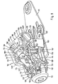
- FIGS. 9 to 12 one is applied the top of a ski, not shown, firmly arranged Base plate 101 a skeleton-like fixedly connected to it Housing structure 102. These are in the front area two guide links on both sides of a vertical central longitudinal plane 103 pivotally mounted about vertical axes, wherein bearing play ensures that the control arm 103 also something about one of their housing-side bearing parts penetrating transverse axis are pivotable. At their in Fig. 9 the rear ends of the guide links 103 each carry two vertically approximately overlapping hinge eyes 103 ', which for storing sole holder parts indicated only in FIG. 10 104 serve, in their normal position the front sole end grasp laterally and thus hold in the transverse direction.
- the guide links 103 are at their upper Articulated eyes 103 'articulated with one another via a flat band 105 connected so that they are always together in the transverse direction swing.
- the guide links 103 deflected towards the viewer.
- the flat sole 105 is the front sole edge from above overlapping sole holder part 106 arranged which the front transverse edge of the flat belt 105 with hook-like extensions 106 'with which the sole holder part 106 the front edge of the flat belt 105 is held pivotally becomes.
- the rear transverse edge of the sole holder part 106 is as downward ledge 107 formed the bottom of the flat belt 105 in the normal position of the sole holder part 106 protrudes downwards and from above on the edge of the front Sole of the ski boot rests.
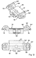
- the prism bodies 108 each have a narrow median strip without sideways inclination, adjoining on both sides Sloping surfaces 108 'with a small sideways slope of for example 8 ° and adjoining edges 108 " steep gradient of, for example, 50 ° to the horizontal.
- the housing structure 102 has one between the guide links 103 arranged stiffening part 109, which with Feet 109 ', which act as pivot axes of the guide link 103 serve, is held on an underside of the housing and with a essentially horizontal top 109 "on two stable Housing columns 110 is supported. Laterally outside of the columns 110 are two beads 111 on the upper part 109 " downward-facing convex side.
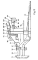
- the housing structure 102 forms in a front section a longitudinal guide for a spring abutment 112, which in fundamentally known manner by means of a not shown Set screw, which is held by a receiving part 113 becomes displaceable and adjustable in the longitudinal direction is.
- This spring abutment 112 supports one in the longitudinal direction arranged, not shown helical compression spring, the controls a basically known locking arrangement with which the guide link 103 in a sideways release Be held in the middle position.
- At the spring abutment 112 are two fork-like ones pointing backwards in the longitudinal direction of the ski Extensions 114 arranged vertically downward supported on projections on the stiffening part 109 are and ramp-like sloping upper edges 114 '.
- a spring member 115 is on the columns 110 in the longitudinal and transverse directions of the shoe holder assembly firmly held.
- This The spring part has a top view in the area of the columns and of the upper part 109 "of the stiffening part 109 a H-shaped shape, with the H crossbar in the longitudinal direction behind the top 109 "is arranged.
- the backwards facing ends of the H-side parts act in further below illustrated manner with the prism bodies 108 of the sole holder part 106 together.
- the H-side parts In front of the top part 109 "of the stiffening part 109 are the H-side parts vertically downwards angled, with the parts angled downwards are provided with shoulders 116, which are shown in FIG Interact with the upper edges 114 'of the extensions 114.
- the H-side parts are spring tongue-like with spring clips extending forward in the forward direction 115 'formed between the extensions 114 are connected to each other by a crossbar 117.
- a crossbar 117 Before extensions 118 aligned in the longitudinal direction are connected, between the extensions 114 and shoulders 112 'are supported on the spring abutment 112 without the adjustability of the spring abutment 112 to hinder.
- the spring clips 115 'between the shoulders 116 and the crossbar 117 are spring-like compliant, while those on it areas of the spring part adjoining upwards and backwards 115 are comparatively stiff since the side parts here of the spring part 115 laterally bent edges 115 " and accordingly have a channel profile.
- the guide link 103 and the sole holder part 106 In the normal position, i.e. if the ski boot or its sole properly fixed in the shoe holder assembly the guide link 103 and the sole holder part 106 their Middle position in which the sole holder parts 104 the lateral Grip around the sole edges and the sole holder 106 his last 107 overlaps the front edge of the sole from above.
- the sole holder part 106 lies with its Prism bodies 108 on the prism bodies 119, in such a way that that the narrow central areas of the prism bodies, i.e. whose "rooftops" stand on top of each other.
- the forces to be overcome are determined by the position of the spring abutment 112 and the associated Extensions 114.
- the prism body 119 is a particularly rigid abutment for the prism body 108 of the sole holder part 106. If on the other hand, the spring abutment 112 in FIG. 9 together with the Extensions 114 is shifted to the left, the prism body 119 held comparatively compliant.
- the sole holder part 106 gets more and more Sideways movement an increasing mobility in Upward direction and eventually the shoe can go up release.
- FIG. 14 shows a modification of that shown in FIG. 1 Embodiment.
- the embodiment differs 14 of the embodiment of FIG. 1 in essentially in that the leaf spring 45 of FIG. 1 in 14 is replaced by a comparatively stiff lever part 245 is, which with its left end in Fig. 14 on a fixed part of the housing 3 or essentially ski-proof is supported and in its central area on his Top of the lever member 40 is covered, such that the at the right end of the lever member 245 arranged slider 46 held against a larger movement in the upward direction becomes.
- the lever member 40 can have a curvature cover the top of the lever part 245, these Curvature can be shaped such that with pivoting the lever member 40 clockwise, the slider 46 something is pushed in the downward direction.
- the spring abutment 112 for support of the rocker 215 cooperating side of the rocker 215 be designed as an inclined or curved surface that a possible game between the abutment 112 and the rocker 215 when adjusting the spring abutment 112 is increasingly reduced to the right and / or the seesaw 215 with the prism bodies 119 increasingly against the prism bodies 108 is excited.
- the lever part 245 or the rocker 215 can be plastic parts or formed as parts of a binding housing his.
Landscapes
- Footwear And Its Accessory, Manufacturing Method And Apparatuses (AREA)
Description
- einer zur Auslösung des Skischuhs in dessen Seitwärtsrichtung und Aufwärtsrichtung beweglichen Schuhhalteranordnung,
- einem Federaggregat zur Steuerung der Seitwärtsauslösung des Skischuhes,
- einem Stützaggregat, welches die Schuhhalteranordnung bzw. ein dieselbe halterndes, in Seitwärtsrichtung und Aufwärtsrichtung des Skischuhs bewegliches Tragteil mittels einer Blattfeder oder eines Hebelteiles gegen die Skioberseite spannt, und
- einem Stellorgan, welches mit einem verstellbaren Widerlager des Federaggregates sowie des Stützaggregates zur Simultanverstellung von Stützaggregat und Federaggregat zusammenwirkt bzw. gekoppelt ist.
- Fig. 1
- eine Seitenansicht eines Schuhhalteraggregates 2,
- Fig. 2
- einen vertikalen Längsschnitt,
- Fig. 3
- einen Horizontalschnitt entsprechend der Schnittlinie III-III in Fig. 2, wobei jedoch Kulissenarme 27 nicht dargestellt sind,
- Fig. 4
- einen Horizontalschnitt entsprechend der Schnittlinie IV-IV in Fig. 2,
- Fig. 5
- einen Horizontalschnitt entsprechend der Schnittlinie V-V in Fig. 2,
- Fig. 6
- eine der Fig. 4 entsprechende ausschnittsweise Darstellung, welche die Verhältnisse bei einer Seitwärtsauslösung zeigt,
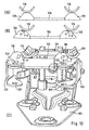
- Fig. 7
- eine der Fig. 2 entsprechende Schnittdarstellung, welche die Verhältnisse bei einer Vertikalauslösung zeigt,
- Fig. 8
- ein Schnittbild entsprechend der Schnittlinie VIII-VIII in Fig. 2,
- Fig. 9
- eine perspektivische Ansicht einer weiteren Ausführungsform,
- Fig.10
- eine Draufsicht dieser Ausführungsform,
- Fig.11
- einen zugehörigen vertikalen Mittellängsschnitt,
- Fig.12
- verschiedene Ansichten eines die Skischuhsohle gegen Aufwärtsbewegung sichernden Schuhhalterteiles dieser Ausführungsform, und zwar eine perspektivische Ansicht, eine Frontansicht und eine Draufsicht,
- Fig.13
- eine perspektivische Rückansicht des Schuhhalteraggregates sowie charakteristische Lagen seiner Elemente,
- Fig.14
- eine der Fig. 1 entsprechende Darstellung einer abgewandelten Ausführung und
- Fig.15
- eine der Fig. 11 entsprechende Darstellung einer weiteren Ausführung.
Claims (12)
- Schuhhalteraggregat einer auslösbaren Skibindung, insbesondere Schuhhalteraggregat (2) zur Halterung des Zehenbereiches eines Skischuhes, miteiner zur Auslösung des Skischuhs in dessen Seitwärtsrichtung und Aufwärtsrichtung beweglichen Schuhhalteranordnung (34;104,106),einem Federaggregat (28) zur Steuerung der Seitwärtsauslösung des Skischuhes,einem Stützaggregat (46;215,245), welches die Schuhhalteranordnung bzw. ein dieselbe halterndes, in Seitwärtsrichtung und Aufwärtsrichtung des Skischuhs bewegliches Tragteil (23;106) mittels einer Blattfeder (45,115) oder eines Hebelteiles (245) gegen die Skioberseite spannt, undeinem Stellorgan (29), welches mit einem verstellbaren Widerlager (30,40;112,114') des Federaggregates sowie des Stützaggregates zur Simultanverstellung von Stützaggregat und Federaggregat zusammenwirkt bzw. gekoppelt ist.
- Schuhhalteraggregat nach Anspruch 1,
dadurch gekennzeichnet, daß das erste Federaggregat eine Schraubendruckfeder (28) aufweist, deren Druckspannung durch ein mittels des Einstellorgans (29) in Richtung der Federachse verstellbares Federwiderlager (30) am einen Ende der Schraubenfeder (28) einstellbar ist. - Schuhhalteraggregat nach Anspruch 2,
dadurch gekennzeichnet, daß das Einstellorgan oder das genannte Federwiderlager mit einem Hebelorgan (40) gekoppelt ist, welches eine verstellbare Abstützung einer als Federelement des zweiten Federaggregates angeordneten Blattfeder (45) oder einer als Teil des Stützaggregates angeordneten Wippe (215) bildet. - Schuhhalteraggregat nach Anspruch 3,
dadurch gekennzeichnet, daß das Hebelorgan (40) mit einer bogenförmigen Abstützfläche der Blattfeder (45) oder des Hebelteiles (245) zusammenwirkt und das Krümmungszentrum der Bogenbahn in die Schwenkachse (41) des Hebelorgans fällt. - Schuhhalteraggregat nach Anspruch 4,
dadurch gekennzeichnet, daß die Bogenbahn durch einen entsprechend gewölbten Bereich der Blattfeder gebildet wird. - Schuhhalteraggregat nach Anspruch 4,
dadurch gekennzeichnet, daß die Bogenbahn an einem blattfederseitigen, von der Blattfeder (45) gesonderten Gleitstück bzw. Formteil ausgebildet ist. - Schuhhalteraggregat nach Anspruch 2,
dadurch gekennzeichnet, daß das erste und zweite Federaggregat (28;115) bzw. das erste Federaggregat und das Stützaggregat (215) ein gemeinsames verstellbares Widerlager (112) aufweisen und das zweite Federaggregat als Blattfeder (115) bzw. das Stützaggregat als Wippe (215) ausgebildet ist. - Schuhhalteraggregat nach einem der Ansprüche 2 bis 7,
dadurch gekennzeichnet, daß die Blattfeder (45;115) oder das Hebelteil (245) bzw. die Wippe (215) mit einem freien Ende einen einen Sohlenrand von oben übergreifenden Schuhhalter (34;106) bzw. eine Schuhhalteranordnung, welche zumindest einen den Sohlenrand von oben übergreifenden Schuhhalter aufweist, und/oder ein Lagerteil (23) des Schuhhalters bzw. der Schuhhalteranordnung in Richtung auf die Oberseite des Skis (1) niederdrückt bzw. niederhält. - Schuhhalteraggregat nach Anspruch 8,
dadurch gekennzeichnet, daß der Schuhhalter (34;106) bzw. die Schuhhalteranordnung bzw. das Lagerteil (23) einerseits und das schuhhalterseitige Ende der Blattfeder (45;115) bzw. des Hebelteiles (245) oder der Wippe (215) andererseits miteinander über Druckübertragungselemente bzw. Druckübertragungsflächen (46,23;119,108) zusammenwirken, welche dem Schuhhalter bzw. der Schuhhalteranordnung bzw. dem Lagerteil relativ zum freien Ende der Blattfeder bzw. des Hebelteiles (245) oder der Wippe (215) eine Seitwärtsbewegung (in Richtung einer Schuh-Querachse) mit vertikaler Aufwärtskomponente ermöglichen. - Schuhhalteraggregat nach Anspruch 8 oder 9,
dadurch gekennzeichnet, daß der Schuhhalter (34) bzw. die Schuhhalteranordnung bzw. das Lagerteil (23) bzw. eine mit diesen Teilen direkt oder indirekt verbundene, den Skischuh abstützende Gleitplatte (8) auf dem Ski (1) über Druckübertragungselemente (4') abgestützt sind, welche dem Schuhhalter bzw. der Schuhhalteranordnung bzw. dem Lagerteil oder der Gleitplatte relativ zur Skioberseite eine Seitwärtsbewegung (in Richtung einer Schuh-Querachse) mit vertikaler Abwärtskomponente ermöglichen. - Schuhhalteraggregat nach einem der Ansprüche 1 bis 10,
dadurch gekennzeichnet, daß der Schuhhalter (34;106) bzw. die Schuhhalteranordnung (104,106) bzw. das Lagerteil (23) oder die Gleitplatte (8) an zwei Führungslenkern (21;103) angeordnet ist, welche im wesentlichen in Skilängsrichtung ausgerichtet sind und um beiderseits der Skilängsachse angeordnete skifeste Hochachsen (20;103') schwenkbar gelagert sind. - Schuhhalteraggregat nach Anspruch 10,
dadurch gekennzeichnet, daß die Hochachsen (20) in einem Bereich dicht vor der Schuhspitze angeordnet sind und die von den Hochachsen entfernten Enden der Führungslenker (21) unter dem Zehenbereich des Skischuhes liegen.
Applications Claiming Priority (2)
| Application Number | Priority Date | Filing Date | Title |
|---|---|---|---|
| DE19636886 | 1996-09-11 | ||
| DE19636886A DE19636886A1 (de) | 1996-09-11 | 1996-09-11 | Schuhhalteraggregat einer auslösbaren Skibindung |
Publications (2)
| Publication Number | Publication Date |
|---|---|
| EP0829281A1 EP0829281A1 (de) | 1998-03-18 |
| EP0829281B1 true EP0829281B1 (de) | 2003-03-19 |
Family
ID=7805243
Family Applications (1)
| Application Number | Title | Priority Date | Filing Date |
|---|---|---|---|
| EP97115296A Expired - Lifetime EP0829281B1 (de) | 1996-09-11 | 1997-09-04 | Schuhhalteraggregat einer auslösbaren Skibindung |
Country Status (4)
| Country | Link |
|---|---|
| US (1) | US5997026A (de) |
| EP (1) | EP0829281B1 (de) |
| AT (1) | ATE234650T1 (de) |
| DE (2) | DE19636886A1 (de) |
Families Citing this family (11)
| Publication number | Priority date | Publication date | Assignee | Title |
|---|---|---|---|---|
| FR2769236B1 (fr) * | 1997-10-03 | 2000-02-04 | Salomon Sa | Cale d'amortissement pour dispositif de retenue d'une chaussure sur une planche de glisse destinee a la pratique du surf sur neige, et dispositif muni d'une telle cale |
| DE19822953A1 (de) * | 1998-05-22 | 1999-11-25 | Marker Deutschland Gmbh | Skibindung |
| FR2806639B1 (fr) * | 2000-03-23 | 2002-06-21 | Emery Sa | Perfectionnement pour dispositif de retenue d'une chaussure de ski sur un ski |
| FR2808454B1 (fr) * | 2000-05-04 | 2002-08-02 | Salomon Sa | Element de retenue de l'avant d'une chaussure sur un ski |
| DE10024384A1 (de) * | 2000-05-17 | 2001-11-29 | Mack Gerd R | Herstellung von dendritischen Zellen aus Rückenmarkstammzellen |
| US6877759B2 (en) * | 2002-08-27 | 2005-04-12 | Louis Dandurand | Ski binding |
| DE102006039989B4 (de) * | 2006-08-25 | 2015-10-08 | Marker Deutschland Gmbh | Schuhhalteraggregat einer Skibindung |
| FR2927818B1 (fr) * | 2008-02-26 | 2011-09-09 | Salomon Sa | Dispositif de declenchement pour fixation d'une chaussure sur un engin de glisse |
| AT506526B1 (de) * | 2008-02-29 | 2012-07-15 | Atomic Austria Gmbh | Vorderbacken einer sicherheitsschibindung |
| DE102011009118B4 (de) | 2011-01-21 | 2022-03-17 | Marker Deutschland Gmbh | Skibindung für Skischuhe unterschiedlicher Art |
| FR2993470B1 (fr) * | 2012-07-19 | 2015-05-29 | Salomon Sas | Dispositifs de retenue avant d'une planche de glisse |
Family Cites Families (13)
| Publication number | Priority date | Publication date | Assignee | Title |
|---|---|---|---|---|
| FR2045158A5 (de) * | 1969-06-10 | 1971-02-26 | Salomon Georges P J | |
| DE2429610C3 (de) * | 1974-06-20 | 1982-07-22 | Geze Gmbh, 7250 Leonberg | Sicherheitsskibindung |
| DE2629452A1 (de) * | 1976-06-30 | 1978-01-05 | Walter Manfreda | Schibindung |
| DE2802775C2 (de) * | 1978-01-23 | 1981-10-15 | Geze Gmbh, 7250 Leonberg | Sicherheitsskibindung mit einem um eine Querachse schwenkbaren Gehäuse |
| DE3403472A1 (de) * | 1984-02-01 | 1985-08-08 | Marker Patentverwertungsgesellschaft mbH, Baar | Vorderbacken fuer sicherheits-skibindungen |
| CH673403A5 (en) * | 1987-12-23 | 1990-03-15 | Marker Deutschland Gmbh | Front jaw for ski-binding - has two supporting members for flat w-shaped pedal and are spaced apart for distance corresponding to amount of elastic movement |
| FR2640516B1 (fr) * | 1988-12-16 | 1991-03-29 | Salomon Sa | Fixation de securite pour ski destinee a maintenir, de facon declenchable, l'avant d'une chaussure montee sur le ski |
| DE4023569A1 (de) * | 1990-07-25 | 1992-01-30 | Salem Francis Gnanapragasam | Bohrer - schleifgeraet |
| IT223065Z2 (it) * | 1990-10-09 | 1995-06-09 | Nordica Spa | Struttura di attacco di sicurezza particolarmente per sci |
| FR2672507B1 (fr) * | 1991-02-12 | 1993-06-04 | Salomon Sa | Butee-avant de securite pour fixation de ski. |
| DE4203569A1 (de) * | 1992-02-07 | 1993-08-12 | Look Sa | Sicherheitsvorderbacken einer skibindung |
| AT399102B (de) * | 1993-02-15 | 1995-03-27 | Tyrolia Freizeitgeraete | Sicherheitsbindung |
| FR2718048B1 (fr) * | 1994-03-30 | 1996-05-31 | Salomon Sa | Elément et ensemble de retenue d'une chaussure sur une planche de glisse. |
-
1996
- 1996-09-11 DE DE19636886A patent/DE19636886A1/de not_active Withdrawn
-
1997
- 1997-09-04 DE DE59709546T patent/DE59709546D1/de not_active Expired - Lifetime
- 1997-09-04 EP EP97115296A patent/EP0829281B1/de not_active Expired - Lifetime
- 1997-09-04 AT AT97115296T patent/ATE234650T1/de not_active IP Right Cessation
- 1997-09-05 US US08/927,127 patent/US5997026A/en not_active Expired - Fee Related
Also Published As
| Publication number | Publication date |
|---|---|
| EP0829281A1 (de) | 1998-03-18 |
| ATE234650T1 (de) | 2003-04-15 |
| DE19636886A1 (de) | 1998-03-12 |
| DE59709546D1 (de) | 2003-04-24 |
| US5997026A (en) | 1999-12-07 |
Similar Documents
| Publication | Publication Date | Title |
|---|---|---|
| DE4135899C2 (de) | Schibindung mit einer Längenverstellvorrichtung für den Abstand zwischen dem Vorder- und Fersenbacken | |
| EP0778055B1 (de) | Bindung für Snowboards | |
| DE202009019128U1 (de) | Zeheneinheit für Tourenskibindung | |
| DE2533337C3 (de) | Auslöseskibindung | |
| DE69616838T2 (de) | Skischuhbindungssystem für Snowboards | |
| EP1379317B1 (de) | Einrichtung zur verbindung eines sportschuhes mit einer gleiteinrichtung | |
| EP3566754B1 (de) | Frontautomat für eine skibindung | |
| DE2942806A1 (de) | Vorrichtung zum festhalten eines skistiefelendes auf einem ski, insbesondere bindung fuer einen langlaufski | |
| EP3928842B1 (de) | Vordereinheit für eine tourenbindung | |
| EP3702005B1 (de) | Fersenautomat | |
| EP0829281B1 (de) | Schuhhalteraggregat einer auslösbaren Skibindung | |
| EP3345659B1 (de) | Fersenautomat für eine skibindung | |
| DE69401171T2 (de) | Bindungselement für einen alpinen Ski | |
| EP1559455B1 (de) | Tourengeeignete Skibindung | |
| EP1428559B1 (de) | Auslösbare Skibindung | |
| DE3915531A1 (de) | Langlaufskibindung | |
| DE2707626A1 (de) | Langlaufbindung | |
| CH638103A5 (de) | Skibindung. | |
| DE3405861C2 (de) | Langlauf- bzw. Wanderbindung | |
| EP1586354A1 (de) | Langlauf- oder Telemarkbindung, sowie daran angepasste Schuhe | |
| DE3151162A1 (de) | Ausloeseskibindung | |
| EP0829282B1 (de) | Schuhhalteraggregat einer auslösbaren Skibindung | |
| DE4424737C1 (de) | Snowboardbindung | |
| DE3202267A1 (de) | Fersenhalter einer skibindung mit skibremse | |
| DE60300256T2 (de) | Kupplungsvorrichtung an der Vorderseite für ein Sportgerät |
Legal Events
| Date | Code | Title | Description |
|---|---|---|---|
| PUAI | Public reference made under article 153(3) epc to a published international application that has entered the european phase |
Free format text: ORIGINAL CODE: 0009012 |
|
| AK | Designated contracting states |
Kind code of ref document: A1 Designated state(s): AT CH DE FR IT LI |
|
| 17P | Request for examination filed |
Effective date: 19980724 |
|
| AKX | Designation fees paid |
Free format text: AT CH DE FR IT LI |
|
| RBV | Designated contracting states (corrected) |
Designated state(s): AT CH DE FR IT LI |
|
| GRAH | Despatch of communication of intention to grant a patent |
Free format text: ORIGINAL CODE: EPIDOS IGRA |
|
| GRAH | Despatch of communication of intention to grant a patent |
Free format text: ORIGINAL CODE: EPIDOS IGRA |
|
| GRAA | (expected) grant |
Free format text: ORIGINAL CODE: 0009210 |
|
| AK | Designated contracting states |
Designated state(s): AT CH DE FR IT LI |
|
| REG | Reference to a national code |
Ref country code: CH Ref legal event code: EP |
|
| REF | Corresponds to: |
Ref document number: 59709546 Country of ref document: DE Date of ref document: 20030424 Kind code of ref document: P |
|
| ET | Fr: translation filed | ||
| PLBE | No opposition filed within time limit |
Free format text: ORIGINAL CODE: 0009261 |
|
| STAA | Information on the status of an ep patent application or granted ep patent |
Free format text: STATUS: NO OPPOSITION FILED WITHIN TIME LIMIT |
|
| 26N | No opposition filed |
Effective date: 20031222 |
|
| PGFP | Annual fee paid to national office [announced via postgrant information from national office to epo] |
Ref country code: CH Payment date: 20070925 Year of fee payment: 11 Ref country code: AT Payment date: 20070926 Year of fee payment: 11 |
|
| PGFP | Annual fee paid to national office [announced via postgrant information from national office to epo] |
Ref country code: IT Payment date: 20070919 Year of fee payment: 11 |
|
| PGFP | Annual fee paid to national office [announced via postgrant information from national office to epo] |
Ref country code: FR Payment date: 20070920 Year of fee payment: 11 |
|
| REG | Reference to a national code |
Ref country code: CH Ref legal event code: PL |
|
| REG | Reference to a national code |
Ref country code: FR Ref legal event code: ST Effective date: 20090529 |
|
| PG25 | Lapsed in a contracting state [announced via postgrant information from national office to epo] |
Ref country code: IT Free format text: LAPSE BECAUSE OF NON-PAYMENT OF DUE FEES Effective date: 20080904 Ref country code: AT Free format text: LAPSE BECAUSE OF NON-PAYMENT OF DUE FEES Effective date: 20080904 |
|
| PG25 | Lapsed in a contracting state [announced via postgrant information from national office to epo] |
Ref country code: LI Free format text: LAPSE BECAUSE OF NON-PAYMENT OF DUE FEES Effective date: 20080930 Ref country code: FR Free format text: LAPSE BECAUSE OF NON-PAYMENT OF DUE FEES Effective date: 20080930 Ref country code: CH Free format text: LAPSE BECAUSE OF NON-PAYMENT OF DUE FEES Effective date: 20080930 |
|
| PGFP | Annual fee paid to national office [announced via postgrant information from national office to epo] |
Ref country code: DE Payment date: 20121102 Year of fee payment: 16 |
|
| REG | Reference to a national code |
Ref country code: DE Ref legal event code: R119 Ref document number: 59709546 Country of ref document: DE Effective date: 20140401 |
|
| PG25 | Lapsed in a contracting state [announced via postgrant information from national office to epo] |
Ref country code: DE Free format text: LAPSE BECAUSE OF NON-PAYMENT OF DUE FEES Effective date: 20140401 |