EP0829357A1 - Tete d'imprimante a jet d'encre, procede de fabrication associe, et encre - Google Patents
Tete d'imprimante a jet d'encre, procede de fabrication associe, et encre Download PDFInfo
- Publication number
- EP0829357A1 EP0829357A1 EP97900445A EP97900445A EP0829357A1 EP 0829357 A1 EP0829357 A1 EP 0829357A1 EP 97900445 A EP97900445 A EP 97900445A EP 97900445 A EP97900445 A EP 97900445A EP 0829357 A1 EP0829357 A1 EP 0829357A1
- Authority
- EP
- European Patent Office
- Prior art keywords
- ink
- jet printer
- printer head
- ink jet
- nozzle
- Prior art date
- Legal status (The legal status is an assumption and is not a legal conclusion. Google has not performed a legal analysis and makes no representation as to the accuracy of the status listed.)
- Granted
Links
- 238000004519 manufacturing process Methods 0.000 title claims description 8
- 150000003464 sulfur compounds Chemical class 0.000 claims abstract description 68
- 229910052751 metal Inorganic materials 0.000 claims abstract description 49
- 239000002184 metal Substances 0.000 claims abstract description 49
- XLYOFNOQVPJJNP-UHFFFAOYSA-N water Substances O XLYOFNOQVPJJNP-UHFFFAOYSA-N 0.000 claims abstract description 22
- -1 thiol compounds Chemical class 0.000 claims description 78
- 230000002940 repellent Effects 0.000 claims description 48
- 239000005871 repellent Substances 0.000 claims description 48
- 239000000126 substance Substances 0.000 claims description 28
- 229910052710 silicon Inorganic materials 0.000 claims description 14
- 239000010703 silicon Substances 0.000 claims description 14
- PXHVJJICTQNCMI-UHFFFAOYSA-N Nickel Chemical compound [Ni] PXHVJJICTQNCMI-UHFFFAOYSA-N 0.000 claims description 9
- 239000000463 material Substances 0.000 claims description 9
- 239000000203 mixture Substances 0.000 claims description 8
- 239000000919 ceramic Substances 0.000 claims description 7
- 230000008859 change Effects 0.000 claims description 7
- 150000003573 thiols Chemical class 0.000 claims description 6
- 229910045601 alloy Inorganic materials 0.000 claims description 4
- 239000000956 alloy Substances 0.000 claims description 4
- 150000002739 metals Chemical class 0.000 claims description 4
- 239000004215 Carbon black (E152) Substances 0.000 claims description 3
- VYZAMTAEIAYCRO-UHFFFAOYSA-N Chromium Chemical compound [Cr] VYZAMTAEIAYCRO-UHFFFAOYSA-N 0.000 claims description 3
- 229930195733 hydrocarbon Natural products 0.000 claims description 3
- 229910052759 nickel Inorganic materials 0.000 claims description 3
- 230000003068 static effect Effects 0.000 claims description 3
- RTAQQCXQSZGOHL-UHFFFAOYSA-N Titanium Chemical compound [Ti] RTAQQCXQSZGOHL-UHFFFAOYSA-N 0.000 claims description 2
- 239000010936 titanium Substances 0.000 claims description 2
- 229910052719 titanium Inorganic materials 0.000 claims description 2
- 229910052715 tantalum Inorganic materials 0.000 claims 1
- GUVRBAGPIYLISA-UHFFFAOYSA-N tantalum atom Chemical compound [Ta] GUVRBAGPIYLISA-UHFFFAOYSA-N 0.000 claims 1
- PCHJSUWPFVWCPO-UHFFFAOYSA-N gold Chemical group [Au] PCHJSUWPFVWCPO-UHFFFAOYSA-N 0.000 abstract description 53
- 125000004434 sulfur atom Chemical group 0.000 abstract description 4
- 239000010409 thin film Substances 0.000 abstract 1
- 239000000976 ink Substances 0.000 description 418
- 238000011156 evaluation Methods 0.000 description 58
- 239000010931 gold Substances 0.000 description 53
- 229910052737 gold Inorganic materials 0.000 description 50
- LFQSCWFLJHTTHZ-UHFFFAOYSA-N Ethanol Chemical compound CCO LFQSCWFLJHTTHZ-UHFFFAOYSA-N 0.000 description 49
- 238000000034 method Methods 0.000 description 37
- 230000001070 adhesive effect Effects 0.000 description 31
- HEDRZPFGACZZDS-UHFFFAOYSA-N Chloroform Chemical compound ClC(Cl)Cl HEDRZPFGACZZDS-UHFFFAOYSA-N 0.000 description 24
- 235000019441 ethanol Nutrition 0.000 description 23
- YMWUJEATGCHHMB-UHFFFAOYSA-N Dichloromethane Chemical compound ClCCl YMWUJEATGCHHMB-UHFFFAOYSA-N 0.000 description 18
- 229920001971 elastomer Polymers 0.000 description 17
- 229920001084 poly(chloroprene) Polymers 0.000 description 16
- 230000005856 abnormality Effects 0.000 description 14
- 230000004044 response Effects 0.000 description 14
- 238000012360 testing method Methods 0.000 description 14
- XUIMIQQOPSSXEZ-UHFFFAOYSA-N Silicon Chemical compound [Si] XUIMIQQOPSSXEZ-UHFFFAOYSA-N 0.000 description 13
- 229910001220 stainless steel Inorganic materials 0.000 description 13
- 239000010935 stainless steel Substances 0.000 description 13
- 238000010586 diagram Methods 0.000 description 11
- 230000005499 meniscus Effects 0.000 description 8
- VNNRSPGTAMTISX-UHFFFAOYSA-N chromium nickel Chemical compound [Cr].[Ni] VNNRSPGTAMTISX-UHFFFAOYSA-N 0.000 description 5
- 238000005259 measurement Methods 0.000 description 5
- 229910001120 nichrome Inorganic materials 0.000 description 5
- 125000000217 alkyl group Chemical group 0.000 description 4
- 230000015572 biosynthetic process Effects 0.000 description 4
- 239000002904 solvent Substances 0.000 description 4
- 238000009736 wetting Methods 0.000 description 4
- LYCAIKOWRPUZTN-UHFFFAOYSA-N Ethylene glycol Chemical compound OCCO LYCAIKOWRPUZTN-UHFFFAOYSA-N 0.000 description 3
- 244000137852 Petrea volubilis Species 0.000 description 3
- 150000001875 compounds Chemical class 0.000 description 3
- 230000006866 deterioration Effects 0.000 description 3
- 239000000428 dust Substances 0.000 description 3
- 239000000975 dye Substances 0.000 description 3
- 238000007373 indentation Methods 0.000 description 3
- 238000001338 self-assembly Methods 0.000 description 3
- JBRZTFJDHDCESZ-UHFFFAOYSA-N AsGa Chemical compound [As]#[Ga] JBRZTFJDHDCESZ-UHFFFAOYSA-N 0.000 description 2
- MCMNRKCIXSYSNV-UHFFFAOYSA-N Zirconium dioxide Chemical compound O=[Zr]=O MCMNRKCIXSYSNV-UHFFFAOYSA-N 0.000 description 2
- 239000003795 chemical substances by application Substances 0.000 description 2
- 230000000052 comparative effect Effects 0.000 description 2
- 239000010949 copper Substances 0.000 description 2
- 239000013078 crystal Substances 0.000 description 2
- 239000012153 distilled water Substances 0.000 description 2
- 230000000694 effects Effects 0.000 description 2
- 125000001183 hydrocarbyl group Chemical group 0.000 description 2
- 230000006872 improvement Effects 0.000 description 2
- 238000010030 laminating Methods 0.000 description 2
- 230000008569 process Effects 0.000 description 2
- 150000003839 salts Chemical class 0.000 description 2
- 150000003376 silicon Chemical class 0.000 description 2
- 150000003377 silicon compounds Chemical class 0.000 description 2
- 238000001179 sorption measurement Methods 0.000 description 2
- 239000007921 spray Substances 0.000 description 2
- 229910052717 sulfur Inorganic materials 0.000 description 2
- 125000003396 thiol group Chemical group [H]S* 0.000 description 2
- QGZKDVFQNNGYKY-UHFFFAOYSA-O Ammonium Chemical compound [NH4+] QGZKDVFQNNGYKY-UHFFFAOYSA-O 0.000 description 1
- BHPQYMZQTOCNFJ-UHFFFAOYSA-N Calcium cation Chemical compound [Ca+2] BHPQYMZQTOCNFJ-UHFFFAOYSA-N 0.000 description 1
- RYGMFSIKBFXOCR-UHFFFAOYSA-N Copper Chemical compound [Cu] RYGMFSIKBFXOCR-UHFFFAOYSA-N 0.000 description 1
- BWGNESOTFCXPMA-UHFFFAOYSA-N Dihydrogen disulfide Chemical compound SS BWGNESOTFCXPMA-UHFFFAOYSA-N 0.000 description 1
- FKNQFGJONOIPTF-UHFFFAOYSA-N Sodium cation Chemical compound [Na+] FKNQFGJONOIPTF-UHFFFAOYSA-N 0.000 description 1
- NINIDFKCEFEMDL-UHFFFAOYSA-N Sulfur Chemical compound [S] NINIDFKCEFEMDL-UHFFFAOYSA-N 0.000 description 1
- 239000002253 acid Substances 0.000 description 1
- 239000000853 adhesive Substances 0.000 description 1
- 229910001424 calcium ion Inorganic materials 0.000 description 1
- 239000003054 catalyst Substances 0.000 description 1
- 238000006243 chemical reaction Methods 0.000 description 1
- 238000004140 cleaning Methods 0.000 description 1
- 229910052802 copper Inorganic materials 0.000 description 1
- 238000005260 corrosion Methods 0.000 description 1
- 238000009826 distribution Methods 0.000 description 1
- 238000005553 drilling Methods 0.000 description 1
- 239000013013 elastic material Substances 0.000 description 1
- 230000008030 elimination Effects 0.000 description 1
- 238000003379 elimination reaction Methods 0.000 description 1
- 238000005516 engineering process Methods 0.000 description 1
- 238000005530 etching Methods 0.000 description 1
- 238000001704 evaporation Methods 0.000 description 1
- 239000000835 fiber Substances 0.000 description 1
- 150000004673 fluoride salts Chemical class 0.000 description 1
- 150000002222 fluorine compounds Chemical class 0.000 description 1
- 239000011521 glass Substances 0.000 description 1
- 238000009499 grossing Methods 0.000 description 1
- 238000007654 immersion Methods 0.000 description 1
- 229910052738 indium Inorganic materials 0.000 description 1
- APFVFJFRJDLVQX-UHFFFAOYSA-N indium atom Chemical compound [In] APFVFJFRJDLVQX-UHFFFAOYSA-N 0.000 description 1
- 239000007788 liquid Substances 0.000 description 1
- 230000007246 mechanism Effects 0.000 description 1
- 239000000155 melt Substances 0.000 description 1
- 238000004377 microelectronic Methods 0.000 description 1
- 238000012544 monitoring process Methods 0.000 description 1
- 239000002120 nanofilm Substances 0.000 description 1
- 150000002894 organic compounds Chemical class 0.000 description 1
- 150000002898 organic sulfur compounds Chemical class 0.000 description 1
- 230000003647 oxidation Effects 0.000 description 1
- 238000007254 oxidation reaction Methods 0.000 description 1
- 238000010979 pH adjustment Methods 0.000 description 1
- 230000035515 penetration Effects 0.000 description 1
- 238000007747 plating Methods 0.000 description 1
- 238000012545 processing Methods 0.000 description 1
- 230000008439 repair process Effects 0.000 description 1
- 238000000926 separation method Methods 0.000 description 1
- 229910001415 sodium ion Inorganic materials 0.000 description 1
- 239000007787 solid Substances 0.000 description 1
- 230000002269 spontaneous effect Effects 0.000 description 1
- 238000004544 sputter deposition Methods 0.000 description 1
- 239000011593 sulfur Substances 0.000 description 1
- 238000006557 surface reaction Methods 0.000 description 1
- 239000004094 surface-active agent Substances 0.000 description 1
- 239000004753 textile Substances 0.000 description 1
- 150000007944 thiolates Chemical class 0.000 description 1
Images



Classifications
-
- B—PERFORMING OPERATIONS; TRANSPORTING
- B41—PRINTING; LINING MACHINES; TYPEWRITERS; STAMPS
- B41J—TYPEWRITERS; SELECTIVE PRINTING MECHANISMS, i.e. MECHANISMS PRINTING OTHERWISE THAN FROM A FORME; CORRECTION OF TYPOGRAPHICAL ERRORS
- B41J2/00—Typewriters or selective printing mechanisms characterised by the printing or marking process for which they are designed
- B41J2/005—Typewriters or selective printing mechanisms characterised by the printing or marking process for which they are designed characterised by bringing liquid or particles selectively into contact with a printing material
- B41J2/01—Ink jet
- B41J2/135—Nozzles
-
- B—PERFORMING OPERATIONS; TRANSPORTING
- B41—PRINTING; LINING MACHINES; TYPEWRITERS; STAMPS
- B41J—TYPEWRITERS; SELECTIVE PRINTING MECHANISMS, i.e. MECHANISMS PRINTING OTHERWISE THAN FROM A FORME; CORRECTION OF TYPOGRAPHICAL ERRORS
- B41J2/00—Typewriters or selective printing mechanisms characterised by the printing or marking process for which they are designed
- B41J2/005—Typewriters or selective printing mechanisms characterised by the printing or marking process for which they are designed characterised by bringing liquid or particles selectively into contact with a printing material
- B41J2/01—Ink jet
- B41J2/135—Nozzles
- B41J2/16—Production of nozzles
- B41J2/1621—Manufacturing processes
- B41J2/1626—Manufacturing processes etching
-
- B—PERFORMING OPERATIONS; TRANSPORTING
- B41—PRINTING; LINING MACHINES; TYPEWRITERS; STAMPS
- B41J—TYPEWRITERS; SELECTIVE PRINTING MECHANISMS, i.e. MECHANISMS PRINTING OTHERWISE THAN FROM A FORME; CORRECTION OF TYPOGRAPHICAL ERRORS
- B41J2/00—Typewriters or selective printing mechanisms characterised by the printing or marking process for which they are designed
- B41J2/005—Typewriters or selective printing mechanisms characterised by the printing or marking process for which they are designed characterised by bringing liquid or particles selectively into contact with a printing material
- B41J2/01—Ink jet
- B41J2/135—Nozzles
- B41J2/14—Structure thereof only for on-demand ink jet heads
- B41J2/14201—Structure of print heads with piezoelectric elements
- B41J2/14233—Structure of print heads with piezoelectric elements of film type, deformed by bending and disposed on a diaphragm
-
- B—PERFORMING OPERATIONS; TRANSPORTING
- B41—PRINTING; LINING MACHINES; TYPEWRITERS; STAMPS
- B41J—TYPEWRITERS; SELECTIVE PRINTING MECHANISMS, i.e. MECHANISMS PRINTING OTHERWISE THAN FROM A FORME; CORRECTION OF TYPOGRAPHICAL ERRORS
- B41J2/00—Typewriters or selective printing mechanisms characterised by the printing or marking process for which they are designed
- B41J2/005—Typewriters or selective printing mechanisms characterised by the printing or marking process for which they are designed characterised by bringing liquid or particles selectively into contact with a printing material
- B41J2/01—Ink jet
- B41J2/135—Nozzles
- B41J2/16—Production of nozzles
- B41J2/1606—Coating the nozzle area or the ink chamber
-
- B—PERFORMING OPERATIONS; TRANSPORTING
- B41—PRINTING; LINING MACHINES; TYPEWRITERS; STAMPS
- B41J—TYPEWRITERS; SELECTIVE PRINTING MECHANISMS, i.e. MECHANISMS PRINTING OTHERWISE THAN FROM A FORME; CORRECTION OF TYPOGRAPHICAL ERRORS
- B41J2/00—Typewriters or selective printing mechanisms characterised by the printing or marking process for which they are designed
- B41J2/005—Typewriters or selective printing mechanisms characterised by the printing or marking process for which they are designed characterised by bringing liquid or particles selectively into contact with a printing material
- B41J2/01—Ink jet
- B41J2/135—Nozzles
- B41J2/16—Production of nozzles
- B41J2/1607—Production of print heads with piezoelectric elements
- B41J2/161—Production of print heads with piezoelectric elements of film type, deformed by bending and disposed on a diaphragm
-
- B—PERFORMING OPERATIONS; TRANSPORTING
- B41—PRINTING; LINING MACHINES; TYPEWRITERS; STAMPS
- B41J—TYPEWRITERS; SELECTIVE PRINTING MECHANISMS, i.e. MECHANISMS PRINTING OTHERWISE THAN FROM A FORME; CORRECTION OF TYPOGRAPHICAL ERRORS
- B41J2/00—Typewriters or selective printing mechanisms characterised by the printing or marking process for which they are designed
- B41J2/005—Typewriters or selective printing mechanisms characterised by the printing or marking process for which they are designed characterised by bringing liquid or particles selectively into contact with a printing material
- B41J2/01—Ink jet
- B41J2/135—Nozzles
- B41J2/16—Production of nozzles
- B41J2/162—Manufacturing of the nozzle plates
-
- B—PERFORMING OPERATIONS; TRANSPORTING
- B41—PRINTING; LINING MACHINES; TYPEWRITERS; STAMPS
- B41J—TYPEWRITERS; SELECTIVE PRINTING MECHANISMS, i.e. MECHANISMS PRINTING OTHERWISE THAN FROM A FORME; CORRECTION OF TYPOGRAPHICAL ERRORS
- B41J2/00—Typewriters or selective printing mechanisms characterised by the printing or marking process for which they are designed
- B41J2/005—Typewriters or selective printing mechanisms characterised by the printing or marking process for which they are designed characterised by bringing liquid or particles selectively into contact with a printing material
- B41J2/01—Ink jet
- B41J2/135—Nozzles
- B41J2/16—Production of nozzles
- B41J2/1621—Manufacturing processes
- B41J2/164—Manufacturing processes thin film formation
- B41J2/1643—Manufacturing processes thin film formation thin film formation by plating
-
- B—PERFORMING OPERATIONS; TRANSPORTING
- B41—PRINTING; LINING MACHINES; TYPEWRITERS; STAMPS
- B41J—TYPEWRITERS; SELECTIVE PRINTING MECHANISMS, i.e. MECHANISMS PRINTING OTHERWISE THAN FROM A FORME; CORRECTION OF TYPOGRAPHICAL ERRORS
- B41J2/00—Typewriters or selective printing mechanisms characterised by the printing or marking process for which they are designed
- B41J2/005—Typewriters or selective printing mechanisms characterised by the printing or marking process for which they are designed characterised by bringing liquid or particles selectively into contact with a printing material
- B41J2/01—Ink jet
- B41J2/135—Nozzles
- B41J2/16—Production of nozzles
- B41J2/1621—Manufacturing processes
- B41J2/164—Manufacturing processes thin film formation
- B41J2/1646—Manufacturing processes thin film formation thin film formation by sputtering
-
- B—PERFORMING OPERATIONS; TRANSPORTING
- B41—PRINTING; LINING MACHINES; TYPEWRITERS; STAMPS
- B41J—TYPEWRITERS; SELECTIVE PRINTING MECHANISMS, i.e. MECHANISMS PRINTING OTHERWISE THAN FROM A FORME; CORRECTION OF TYPOGRAPHICAL ERRORS
- B41J2/00—Typewriters or selective printing mechanisms characterised by the printing or marking process for which they are designed
- B41J2/005—Typewriters or selective printing mechanisms characterised by the printing or marking process for which they are designed characterised by bringing liquid or particles selectively into contact with a printing material
- B41J2/01—Ink jet
- B41J2/135—Nozzles
- B41J2/14—Structure thereof only for on-demand ink jet heads
- B41J2002/14387—Front shooter
Definitions
- the present invention relates to an ink jet printer head.
- the present invention relates to an improvement of a nozzle surface of the ink jet printer head which selectively attaches ink drops to a recording medium.
- ink, paper dust and the like attaches on the nozzle surface.
- the ink drops which are being ejected out of the nozzle are attracted to these attachments and the ink drops are ejected in a direction that is different from the original ejection direction. If the amount of such attachments is large, the proper ink drops are not formed.
- ink repellant properties e.g., water repellant property
- the nozzle surface on which silicon compounds and the like are formed has presented a problem in that the nozzle surface has poor resistance against various inks.
- the silicon type compound has a siloxane bond (Si ⁇ O) as part of its basic structure.
- the siloxane bond is easily cleaved by a base.
- the resistance of the nozzle surface has been weak against the inks containing alkaline components.
- the ink used for an ink jet printer contains water in which many components such as dye, solvent and surfactant are added.
- a dye is a salt made of acid and alkaline.
- the salt is ionized in the water and forms a base (ammonium ion, sodium ion, calcium ion and the like).
- a solvent with high level of chemical activity such as one that melts the paper fiber is used. Such solvents naturally also have the function of decomposing the silicon compounds.
- a first object of the present invention is to provide an ink jet printer head with water repellant property without substantial deterioration of its ink drop ejection capability, and to provide a method of making such an ink jet printer head.
- a second object of the present invention is to provide an ink jet printer head which substantially maintains its water repellant property caused by wear of the nozzle surface, and to provide an ink for use therein.
- a first embodiment of the invention achieves the first object.
- the first embodiment is an ink jet printer head, wherein ink drops are ejected from the nozzle being formed on the nozzle surface, wherein a water repellant layer comprising a metal layer containing metal is formed on said nozzle surface, and wherein a sulfur compound layer containing sulfur compounds is formed on said metal layer.
- a second embodiment invention achieves the first object.
- the second embodiment is an ink jet printer head of Claim 1 wherein said water repellant layer comprises an intermediate layer consisting of nickel, chrome, tantaline, or titanium, or an alloy made of these metals between the member forming said nozzle surface and said metal layer.
- a third embodiment of the invention achieves the second object.
- the third embodiment is an ink jet printer head of Claim 1 or Claim 2 wherein said water repellant layer is formed on the inner wall of said nozzle.
- a fourth embodiment of the invention achieves the second object.
- the fourth embodiment is an ink jet printer head of Claim 1 or Claim 2 wherein said nozzle is provided inside indentation section of said nozzle surface.
- a fifth embodiment of the invention achieves the first object.
- the fifth embodiment is an ink jet printer head of Claim 1 or Claim 2 comprising a cavity for filling the ink and a pressure apparatus for causing a volume change in said cavity, wherein ink drops are made to be ejected out of said nozzle by the volume change of said cavity.
- a sixth embodiment of the invention achieves the first object.
- the sixth embodiment is an ink jet printer head of Claim 5 wherein said pressure apparatus is made of a piezoelectric element.
- a seventh embodiment of the invention achieves the first object.
- the seventh embodiment is an ink jet printer head of Claim 5 wherein said pressure apparatus is made of a heat generating element.
- an eighth embodiment of the invention achieves the first object.
- the eighth embodiment is an ink jet printer head wherein said sulfur compounds are thiol compounds.
- a ninth embodiment of the invention achieves the first object.
- the ninth embodiment is an ink jet printer head of Claim 8 wherein said thiol compounds have the following structure: R ⁇ S ⁇ H (R represents a hydrocarbon radical)
- a tenth embodiment of the invention achieves the first object.
- the tenth embodiment is an ink jet printer head of Claim 8 wherein R of said thiol compounds has the following structure: CnH2n+1 ⁇
- the eleventh embodiment is an ink jet printer head of Claim 8 wherein R of said thiol compounds has the following structure: CnF2n+1 ⁇
- a twelfth embodiment of the invention achieves the first object.
- the twelfth embodiment is an ink jet printer head of Claim 8 wherein R of said thiol compounds has the following structure: CnF2n+1-CmH2m ⁇
- a thirteenth embodiment of the invention achieves the first object.
- the thirteenth embodiment is an ink jet printer head of Claim 1 wherein said sulfur compounds comprise a mixture of the following two types of thiol molecules: R1 ⁇ SH, R2 ⁇ SH (R1 and R2 are mutually exclusive chemical structures).
- a fourteenth embodiment of the invention achieves the first object.
- the fourteenth embodiment is an ink jet printer head of Claim 1 wherein said sulfur compounds comprise the following chemical formula: HS ⁇ R3 ⁇ SH.
- a fifteenth embodiment of the invention achieves the first object.
- the fifteenth embodiment is an ink jet printer head of Claim 1 wherein said sulfur compounds comprise the following chemical formula: R4 ⁇ S ⁇ S ⁇ R4
- a sixteenth embodiment of the invention achieves the first object.
- the sixteenth embodiment is an ink jet printer head of Claim 13 wherein R1 and/or R2 of said thiol compounds comprise the following chemical formula: CnF2n+1 ⁇
- a seventeenth embodiment of the invention achieves the first object.
- the seventeenth embodiment is an ink jet printer head of Claim 13 wherein R1 and/or R2 of said thiol compounds comprise the following chemical formula: CnF2n+1-CmH2m ⁇
- an eighteenth embodiment of the invention achieves the first object.
- the eighteenth embodiment is an ink jet printer head of Claim 14 wherein R3 of said thiol compounds comprise the following chemical formula:
- a nineteenth invention achieves the first purpose.
- the nineteenth invention is an ink jet printer head of Claim 14 wherein R3 of said thiol compounds comprise the following chemical formula:
- a twentieth embodiment of the invention achieves the first object.
- the twentieth embodiment is an ink jet printer head of Claim 14 wherein R3 of said thiol compounds comprise the following chemical formula:
- a twenty-first embodiment of the invention achieves the first object.
- the twenty-first embodiment is an ink jet printer head of Claim 14 wherein R3 of said thiol compounds comprise the following chemical formula:
- a twenty-second embodiment of the invention achieves the first object.
- the twenty-second embodiment is an ink jet printer head of Claim 15 wherein R4 of said thiol compounds comprise the following chemical formula: CnF2n+1-CmH2m ⁇
- a twenty-third embodiment of the invention achieves the first object.
- the twenty-third embodiment is an ink jet printer head of Claim 15 wherein R4 of said thiol compounds comprise the following chemical formula: CnF2n+1 ⁇
- a twenty-fourth embodiment of the invention achieves the first object.
- the twenty-fourth embodiment is an ink jet printer head wherein the nozzle member of Claim 1 and Claim 2 is made of silicon or ceramics.
- a twenty-fifth embodiment of the invention achieves the first object.
- the twenty-fifth embodiment is a production method of an ink jet printer head comprising a step to form a metal layer on the nozzle surface of the nozzle element and a step to immerse the material which forms said metal layer in a solution in which sulfur compounds are dissolved.
- a twenty-sixth embodiment of the invention achieves the second object.
- the twenty-sixth embodiment is an ink, of the type of ink used in the ink jet printer head of Claim 1 or Claim 2, containing sulfur compounds.
- a twenty-seventh embodiment of the invention achieves the first object.
- the sulfur compounds of Claim 1 use a material whose static water contact angle on the surface of said sulfur compound layer is more than about 100°.
- Figure 1 An overall perspective diagram of an ink jet printer.
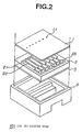
- Figure 2 A perspective diagram describing a structure of an ink jet printer head.
- Figure 3 A perspective view of a major part (sectional cross section) of an ink jet printer head.
- Figure 4 A cross-sectional diagram conceptually depicting operation of an ink jet printer head.
- Figure 5 A cross section of a nozzle plate in a first embodiment.
- Figure 6 A diagram depicting bonding between thiol molecules and gold.
- Figure 7 A diagram depicting bonding between sulfur atoms and gold atoms.
- Figure 8 A diagram depicting arrangement of thiol molecules on a gold surface.
- Figure 9 A diagram depicting ejection of ink from of an ink jet printer head without ink repellant property.
- Figure 10 A diagram depicting ejection of ink from an ink jet printer head with ink repellant property.
- Figure 11 A cross section of a nozzle plate for which an intermediate layer is provided in the first embodiment.
- Figure 12 A cross section of a nozzle plate for which an ink repellant layer is provided in the nozzle in a second embodiment.
- Figure 13 A cross section of a nozzle plate for which a step is provided in the nozzle for the third embodiment.
- Figure 14 An perspective view of an ink printer head which uses a heat generating element in the fourth embodiment.
- FIG. 1 is a perspective diagram of a printer in which an ink jet printer head of the present embodiment is used.
- the ink jet printer 100 of the present embodiment is structured in such a manner that a main body 102 comprises the ink jet printer head 101, a tray 103 and the like which relate to the present invention. Papers 105 are loaded in a tray 103.
- a inner roller (not shown) takes in the paper 105 into the main body 102.
- the papers 105 when passing the vicinity of the roller, are printed by an ink jet printer head 101 which is driven in the direction of the arrow in the figure and is discharged from an discharge opening 104. If the ink drops are not ejected accurately from the ink jet printer head 101, letters and the like which are printed on the papers 105 are smeared or are too light.
- FIG. 2 is a perspective diagram depicting a structure of the ink jet printer head of the present embodiment.
- the ink jet printer head 101 comprises a nozzle plate 1 on which nozzles 11 are provided and a flow path board 2 on which a vibration plate 3 is provided with both plates being fitted in the case 5.
- the flow path board 2 is also called a pressure chamber board and a cavity (pressure chamber) 21, a side wall 22, a reservoir 23 and the like are formed in it.
- the characteristics of the present invention relate to processing of the surface of nozzle plate of the ink jet printer head.
- a reservoir for holding ink is provided on the flow path board but the nozzle plate may be a multi-layer structure and the reservoir may be provided inside of the nozzle plate structure.
- Figure 3 is a perspective diagram depicting a major section of the ink jet printer head which is composed of laminating the flow path board 2 and the vibration plate 3 on the nozzle plate.
- the main unit of the ink jet printer head is structured in such a manner that the flow path board 2 is fitted with the nozzle plate 1 and the vibration plate 3.
- a plurality of cavities 21, each of which functions as pressure chamber, are provided on the flow path board 2.
- Each cavity 21 is separated by the side wall 22.
- Each cavity 21 is connected to the reservoir 23 through a supply opening 24.
- the nozzle 11 is provided in the nozzle plate 1 at the location corresponding to the cavity 21 of the flow path board 2.
- the vibration plate 3 is made of a heat oxidation film.
- a piezoelectric element 4 is formed at the location corresponding to the cavity 21 on the vibration plate 3.
- an ink tank opening 31 is provided in the vibration plate 3.
- the piezoelectric element 4 is structured in such a manner that a PZT element and the like is pinched by the upper electrode and the lower electrode (not shown). The following explanation will be based on the cross section of the ink jet printer head with respect to the line A-A in Figure 3.
- the ink is supplied from the ink tank in the case 5 into the reservoir 23 through the ink tank opening which is provided in the vibration plate 3.
- the ink flows into each cavity 21, from the reservoir 23 through the supply opening 24.
- the volume of piezoelectric element 4 changes when voltage is applied between the upper electrode and the lower electrode. This volume change deforms the vibration plate 3, which in turn changes the volume of the cavity 21.
- the vibration plate 3 does not deform unless the voltage is applied. However, upon application of the voltage, the vibration plate 3 deforms to the position of the post deformation vibration plate 3b, or post deformation piezoelectric element 4b, which are described by broken lines in the figure.
- the pressure of the ink 6 being filled in the cavity rises, causing ink drop 61 to be ejected out of nozzle 11.
- Figure 5 is a cross section depicting layer structure of the nozzle plate in the present embodiment.
- the figure is an enlarged cross section of the vicinity of the nozzle of figure 3 and figure 4.
- the symbol 1a indicates the nozzle plate in the present embodiment.
- Nozzle plate 1a is made of laminating metal layer 13 and sulfur compound layer 14 on the ink drop ejecting side of the nozzle member 12.
- the same structures in figure 2 and figure 3 are identified with the same symbol.
- a meniscus 62a of ink is formed in the nozzle 11a due to surface tension of the ink.
- ink filled in the cavity 21 does not spread over the surface of nozzle plate 1a, but only forms the meniscus 62a in the nozzle 11a, due to ink repellent property of the sulfur compound layer 14.
- the nozzle member 12 may be made of any material as long as it provides certain bonding forces between itself and the metal layer.
- glass or metal plate may be used.
- silicon or ceramics are preferred.
- silicon or ceramic it is preferred to provide an intermediate layer which will be explained later in the present embodiment (see Figure 11).
- metal layer 13 use of gold (Au) is preferred because of its chemical and physical stability.
- Other metals such as (Ag), copper (Cu), indium (In) and gallium-arsenic (Ga-As) which chemically adsorb sulfur compounds may also be used.
- Publicly known techniques such as the sputter method, evaporation method and the plating method, may be used to form metal layer 13 onto the nozzle member 12. The choice of the method is not particularly limited as long as the method is able to form a uniform thickness of the thin metal film (for example 0.1 ⁇ m).
- a sulfur compound layer 14 is formed on the metal layer 13. Formation of the sulfur compound layer 14 is accomplished by dissolving sulfur compound into solution and by immersing the nozzle plate 1a on which the metal layer 13 is formed in the solution.
- the sulfur compound refers to a general name of a compound, among organic containing sulfur (S), which contains one or more thiol functional groups or a compound which forms a disulfide bond (S - S bonding).
- S organic containing sulfur
- S - S bonding a compound which forms a disulfide bond
- These sulfur compounds spontaneously and chemically adsorb to metal surfaces such as gold in the solution or under volatile conditions and form single molecule film that is close to a two dimensional crystal structure.
- the molecule film created by spontaneous and chemical adsorption is called a self-organizing film or a self-assembly film.
- gold Au
- the self-assembly film may be formed equally on other metal surfaces that are mentioned above.
- a thiol compound is preferred as a sulfur compound.
- the thiol compound refers to a general name for an organic compound (R-SH where R represents a hydrocarbon radical such as an alkyl group) containing a mercapto group (-SH).
- FIG. 6 The figure describes a case in which gold is used as a metal layer, and a thiol compound is used as a sulfur compound.
- the thiol compound has an alkyl group or the like for the head section and a mercapto group for the tail section as described in Figure 6 at (a).
- the thiol compound is dissolved with 1 - 10mM ethanol solution.
- a gold film which is created as in Figure 6 at (b) is immersed in the solution.
- thiol compounds begin to be spontaneously assembled on the gold surface ( Figure 6 at (c)).
- a two dimensional single molecule thick film of thiol molecules is formed on the gold surface ( Figure 6 at (d)).
- Figure 7 describes a condition of the bonding between molecules when the single molecule thick film of thiol compound is formed.
- the reaction mechanism of the chemical adsorption of sulfur atoms on the metal surface is not completely known.
- a structure in which an organic sulfur compound is adsorbed on a gold (0) surface as Au (1) thiolate (RS - Au+) may be possible. Bonding of a gold atom of metal layer 13 with a sulfur atom of a sulfur compound layer 14 is close to covalent bonding (40 - 45 kcal/mol) and a very stable molecule film is formed.
- solid surface functionalization techniques such as self-organization of organic molecules into films, may be applied to such field as shining, smoothing, wetting, anti-corrosion, surface catalyst function of the material surface.
- application of this technology in the fields of micro-electronics such as molecular elements, bio-elements and bio-electronics has a promising future.
- Figure 8 depicts a condition wherein a single molecule thick film of sulfur compounds is formed on the surface of the metal layer 13.
- the sulfur compound layer 14 is composed of a single molecule thick layer having a film thickness which is very thin (for example, about 2nm).
- the sulfur compounds gather very tightly preventing water molecules form entering the sulfur compound layer 14.
- the sulfur compound layer 14 displays ink repellent (water repellent) properties.
- ink 6 In an ink jet printer head without ink repellent properties, as described in Figure 9, ink 6 often spreads around the nozzle surface. In this case, ink drops 61a which are ejected are pulled in the direction parallel to the nozzle plate 1' by the tension of ink 6, and fail to be ejected perpendicular to the nozzle plate.
- the nozzle surface possesses ink repellent properties.
- Ink 6 is always repelled at the nozzle surface and pools inside the nozzle 11 as meniscus 62, as depicted in Figure 10.
- the ink drop 61b is not pulled by the tension of the ink and is ejected perpendicular to the nozzle 11.
- the ink repellent properties of the nozzle surface because of the ink repellent properties of the nozzle surface, the ink being ejected on the nozzle surface pools as drop rather than scattering over the nozzle surface. Hence, elimination of unnecessary ink drops may be easily accomplished by means of wiping using an elastic material such as rubber.
- Figure 11 depicts a cross section of a layer structure of the nozzle plate for which an intermediate layer is provided.
- the bonding force is strengthened by providing an intermediate layer between the nozzle member and the metal film.
- the same members in Figure 11 as in Figure 10 are identified by the same symbols and the explanation of these members are omitted.
- the nozzle member 12b is made of silicon or ceramics.
- the intermediate layer 15 is preferably made of a material which strengthen bonding forces between the nozzle member and the metal film such as nickel (Ni), chrome (Cr), tantaline (Ta), or an alloy made of these metals.
- Ni nickel
- Cr chrome
- Ta tantaline
- the bonding force between the nozzle member and the metal layer increases and the separation of the sulfur compound layer by mechanical frictional forces becomes difficult.
- the ink 6 used for the ink jet printer head is preferably mixed with aforementioned sulfur compounds.
- sulfur compounds By mixing sulfur compounds, even when part of the sulfur compounds layer is damaged due to physical impact and the like, the sulfur compounds bond again at the location of damage on the surface of the metal layer. In short, a self-restoration function is provided.
- Ink repellent processes with such self-restoration properties eliminate special restoration operations otherwise required of users.
- formation of a metal layer with gold as depicted in the present embodiments is preferred.
- Gold has superior malleability and gold material is seldom lost even if it is damaged.
- gold has superior anti-chemical properties, which improve anti-chemical properties of the nozzle member.
- Ink repellent property Contact angle with the ink was measured as an evaluation of the ink repellent property. Two types of ink, ink A and ink B, having different surface tension were used for evaluation. The surface tension of ink A was 35dyn/cm and the surface tension of ink B was 19dyn/cm. The contact angle of ink A was found to be 90° and the contact angle of ink B was found to be 60°.
- Adhesive property As an evaluation of adhesive property, the nozzle plate surface was rubbed 5000 times with chloroprene rubber of rubber hardness 60° and with additional load of 100g/cm, after which the contact angles of the ink relative to the nozzle were measured. As a result, all the initial contact angles were preserved and no separated section was observed.
- Anti-ink property As an evaluation of anti-ink properties, the nozzle plate on which thiol compounds were formed was immersed in the ink for 6 days under ambient atmospheric pressure and a temperature of 60° C, after which the contact angles were measured. As a result, all the initial contact angles were preserved and no separated section was observed.
- An ink jet printer head depicted in Figure 10 was constructed using a nozzle plate on which thiol compounds were formed. The ink jet printer head was driven continuously 100,000 times with the response frequency of 10KHz. As a result, all the ink drops were ejected in a normal direction and no abnormality such as bend in the ejection direction was found.
- Ink repellent property Contact angle with the ink was measured as an evaluation of the ink repellent property. Two types of ink, ink A and ink B, having different surface tensions were used for this evaluation. The surface tension of ink A was 35dyn/cm and the surface escape force of ink B was 19dyn/cm. The contact angle of ink A was found to be 90° and the contact angle of ink B was found to be 60°.
- Adhesive property As an evaluation of adhesive properties, the nozzle plate surface was rubbed 5000 times with chloroprene rubber of rubber hardness 60° and with an additional load of 100g/cm, after which the contact angles were measured. As a result, all the initial contact angles were preserved and no separated section was observed.
- Anti-ink property As an evaluation of anti-ink properties, the nozzle plate on which thiol compound was formed was immersed in the ink for 6 days under ambient atmospheric pressure and a temperature of 60° C, after which the contact angle were measured. As a result, all the initial contact angles were preserved and no separated section was observed.
- an alloy film of NiCr was formed in place of intermediate layer with Cr in the embodiment 2.
- Ink repellent property Contact angle with the ink was measured as an evaluation of the ink repellent properties. Two types of ink, ink A and ink B, having different surface tension were used for this evaluation. The surface tension of ink A was 35dyn/cm and the surface tension of ink B was 19dyn/cm. The contact angle of ink A was found to be 90° and the contact angle of ink B was found to be 60°.
- Adhesive property As an evaluation of adhesive properties, the nozzle plate surface was rubbed 5000 times with chloroprene rubber of rubber hardness 60° and with an additional load of 100g/cm, after which the contact angle was measured. As a result, all the initial contact angles were preserved and no separated section was observed.
- Anti-ink property As an evaluation of anti-ink property, the nozzle plate on which thiol compound was formed was immersed in the ink for 6 days under ambient atmospheric pressure and at a temperature of 60° C, after which the contact angle was measured. As a result, all the initial contact angles were preserved and no separated section was observed.
- Ink repellent property Contact angle with the ink was measured as an evaluation of the ink repellent properties. Two types of ink, ink A and ink B, having different surface tension were used for evaluation. The surface tension of ink A was 35dyn/cm and the surface tension of ink B was 19dyn/cm. The contact angle of ink A was found to be 110° and the contact angle of ink B was found to be 70°.
- Adhesive property As an evaluation of adhesive property, the nozzle plate surface was rubbed 5000 times with chloroprene rubber of rubber hardness 60° and with additional load of 100g/cm, after which the contact angle was measured. As a result, all the initial contact angles were preserved and no separated section was observed.
- Anti-ink property As an evaluation of anti-ink properties, the nozzle plate on which thiol compound was formed was immersed in the ink for 6 days under ambient atmospheric pressure and at a temperature of 60° C, after which the contact angle was measured. As a result, all the initial contact angles were preserved and no separated section was observed.
- Ink repellent property Contact angle with the ink was measured as an evaluation of the ink repellent properties. Two types of ink, ink A and ink B, having different surface tension were used for evaluation. The surface tension of ink A was 35dyn/cm and the surface tension of ink B was 19dyn/cm. The contact angle of ink A was found to be 110° and the contact angle of ink B was found to be 70°.
- Adhesive property As an evaluation of adhesive property, the nozzle plate surface was rubbed 5000 times with chloroprene rubber of rubber hardness 60° and with additional load of 100g/cm, after which the contact angle was measured. As a result, all the initial contact angles were preserved and no separated section was observed.
- Anti-ink property As an evaluation of anti-ink property, the nozzle plate on which thiol compound was formed was immersed in the ink for 6 days under ambient atmospheric pressure and at a temperature of 60° C, after which the contact angles were measured. As a result, all the initial contact angles were preserved and no separated section were observed.
- Ink repellent property Contact angle with the ink was measured as an evaluation of the ink repellent properties. Two types of ink, ink A and ink B, having different surface tension were used for evaluation. The surface tension of ink A was 35dyn/cm and the surface tension of ink B was 19dyn/cm. The contact angle of ink A was found to be 90° and the contact angle of ink B was found to be 60°.
- Adhesive property As an evaluation of adhesive property, the nozzle member surface was rubbed 5000 times with chloroprene rubber of rubber hardness 60° and with additional load of 100g/cm, after which the contact angle was measured. As a result, all the initial contact angles were preserved and no separated section was observed.
- Anti-ink property As an evaluation of anti-ink property, the nozzle member on which thiol compound was formed was immersed in the ink for 10 days under ambient atmospheric pressure and a temperature of 60°C, after which the contact angle was measured. As a result, all the initial contact angles were preserved and no separated section was observed.
- a mixture of two different types of thiol compounds was used to mold a nozzle plate.
- Ink repellent property Contact angle with the ink was measured as an evaluation of the ink repellent property. Two types of ink, ink A and ink B, having different surface tension were used for evaluation. The surface tension of ink A was 35dyn/cm and the surface tension of ink B was 19dyn/cm. The contact angle of ink A was found to be 100° and the contact angle of ink B was found to be 70°.
- Adhesive property As an evaluation of adhesive properties, the nozzle plate surface was rubbed 5000 times with chloroprene rubber of rubber hardness 60° and with an additional load of 100g/cm, after which the contact angle was measured. As a result, all the initial contact angles were preserved and no separated section was observed.
- Anti-ink property As an evaluation of anti-ink properties, the nozzle plate on which thiol compound was formed was immersed in the ink for 6 days under ambient atmospheric pressure and a temperature of 60° C, after which the contact angle was measured. As a result, all the initial contact angles were preserved and no separated section was observed.
- Ink repellent property Contact angle with the ink was measured as an evaluation of the ink repellent properties. Two types of ink, ink A and ink B, having different surface tension were used for evaluation. The surface tension of ink A was 35dyn/cm and the surface escape force of ink B was 19dyn/cm. The contact angle of ink A was found to be 110° and the contact angle of ink B was found to be 70°.
- Adhesive property As an evaluation of adhesive property, the nozzle plate surface was rubbed 5000 times with chloroprene rubber of rubber hardness 60° and with additional load of 100g/cm, after which the contact angle was measured. As a result, all the initial contact angles was preserved and no separated section was observed.
- Anti-ink property As an evaluation of anti-ink properties, the nozzle plate on which thiol compound was formed was immersed in the ink for 6 days under ambient atmospheric pressure and a temperature of 60° C, after which the contact angle was measured. As a result, all the initial contact angles were are preserved and no separated section was observed.
- Ink repellent property Contact angle with the ink was measured as an evaluation of the ink repellent properties. Two types of ink, ink A and ink B, having different surface tension were used for evaluation. The surface tension of ink A was 35dyn/cm and the surface tension of ink B was 19dyn/cm. The contact angle of ink A was found to be 110° and the contact angle of ink B was found to be 70°.
- Adhesive property As an evaluation of adhesive properties, the nozzle plate surface was rubbed 5000 times with chloroprene rubber of rubber hardness 60° and with additional load of 100g/cm, after which the contact angle was measured. As a result, all the initial contact angles were preserved and no separated section was observed.
- Anti-ink property As an evaluation of anti-ink properties, the nozzle plate on which thiol compound was formed was immersed in the ink for 6 days under ambient atmospheric pressure and a temperature of 60° C, after which the contact angle was measured. As a result, all the initial contact angles were preserved and no separated section was observed.
- Ink repellant property Contact angle with the ink was measured as an evaluation of the ink repellant properties. Two types of ink, ink A and ink B, having different surface tension were used for evaluation. The surface tension of ink A was 35dyn/cm and the surface tension of ink B was 19dyn/cm. The contact angle of ink A was found to be 100° and the contact angle of ink B was found to be 70°.
- Adhesive property As an evaluation of adhesive properties, the nozzle plate surface was rubbed 5000 times with chloroprene rubber of rubber hardness 60° and with additional load of 100g/cm, after which the contact angle was measured. As a result, all the initial contact angles were preserved and no separated section was observed.
- Anti-ink property As an evaluation of anti-ink properties, the nozzle plate on which thiol compound was formed was immersed in the ink for 6 days under ambient atmospheric pressure and a temperature of 60° C, after which the contact angle was measured. As a result, all the initial contact angles were preserved and no separated section was observed.
- Ink repellent property Contact angle with the ink was measured as an evaluation of the ink repellent property. Two types of ink, ink A and ink B, having different surface tension were used for evaluation. The surface tension of ink A was 35dyn/cm and the surface tension of ink B was 19dyn/cm. The contact angle of ink A was found to be 105° and the contact angle of ink B was found to be 70°.
- Adhesive property As an evaluation of adhesive property, the nozzle plate surface was rubbed 5000 times with chloroprene rubber of rubber hardness 60° and with additional load of 100g/cm, after which the contact angle was measured. As a result, all the initial contact angles were preserved and no separated section was observed.
- Anti-ink property As an evaluation of anti-ink properties, the nozzle plate on which thiol compound was formed was immersed in the ink for 6 days under ambient atmospheric pressure and a temperature of 60° C, after which the contact angle was measured. As a result, all the initial contact angles were preserved and no separated section was observed.
- Ink repellent property Contact angle with the ink was measured as an evaluation of the ink repellent properties. Two types of ink, ink A and ink B, having different surface tension were used for evaluation. The surface tension of ink A was 35dyn/cm and the surface escape force of ink B was 19dyn/cm. The contact angle of ink A was found to be 110° and the contact angle of ink B was found to be 60°.
- Adhesive property As an evaluation of adhesive properties, the nozzle plate surface was rubbed 5000 times with chloroprene rubber of rubber hardness 60° and with additional load of 100g/cm, after which the contact angle was measured. As a result, all the initial contact angles were preserved and no separated section was observed.
- Ink repellent property Contact angle with the ink was measured as an evaluation of the ink repellent properties. Two types of ink, ink A and ink B, having different surface tension were used for evaluation. The surface tension of ink A was 35dyn/cm and the surface tension of ink B was 19dyn/cm. The contact angle of ink A was found to be 100° and the contact angle of ink B was found to be 60°.
- Adhesive property As an evaluation of adhesive property, the nozzle plate surface was rubbed 5000 times with chloroprene rubber of rubber hardness 60° and with additional load of 100g/cm, after which the contact angles was measured. As a result, all the initial contact angles were preserved and no separated section was observed.
- Anti-ink property As an evaluation of anti-ink property, the nozzle plate on which thiol compound was formed was immersed in the ink for 6 days under ambient atmospheric pressure at a temperature of 60° C, after which the contact angle was measured. As a result, all the initial contact angles were preserved and no separated section was observed.
- an ink jet printer head with high level of ink repellent properties and high level of anti-wear properties may be produced.
- a ink repellent layer was formed to the inner wall of the nozzle.
- Figure 12 describes an enlarged cross section of vicinity of the nozzle in the nozzle plate of the configuration of embodiment 2.
- the members that are same as the ones in the aforementioned configuration of embodiment 1 ( Figure 5) are identified by the same symbols and the explanation was omitted.
- the metal layer 13 and the sulfur compound layer 14 are formed onto the inner wall of the nozzle 11c.
- the position where meniscus 62C of ink 6 was formed is moved closer to the cavity 21, due to ink repellant properties of sulfur compound layer 14, than in the case described in Figure 5.
- composition of the metal layer and sulfur compound layer can be considered same as the aforementioned configuration of embodiment 1.
- an ink repellent film is made of the metal layer and the sulfur compound layer in Figure 12, but an ink repellent film with an intermediate layer being provided between the nozzle member and the metal layer, which is shown in Figure 11, may be provided.
- anti-wear properties and anti-impact properties which are strong against mechanical impact, may be achieved because the sulfur compound layer 14 with ink repellent property is formed inside the nozzle 14.
- the configuration of element 2 is extremely effective for usage such as dying of industrial-use textiles and industrial printing which cause scratches on the surface of the nozzle member 12.
- the ink repellent film normally is damaged around the point of contact.
- the shape of the meniscus of the ink changes resulting in deterioration of ink ejecting capability.
- the inner wall 16 which is composed of the ink repellent film is formed inside the nozzle 11c as in the case of the configuration of the present embodiment, the meniscus 62c of the ink forms inside the nozzle. Hence, scratches on the surface do not cause change in the meniscus 62c of the ink and the ink ejection capability does not deteriorate.
- Ink repellant property Contact angle with the ink was measured as an evaluation of the ink repellent properties. Two types of ink, ink A and ink B, having different surface tension were used for evaluation. The surface tension of ink A was 35dyn/cm and the surface tension of ink B was 19dyn/cm. The contact angle of ink A was found to be 90° and the contact angle of ink B was found to be 60°.
- Adhesive property As an evaluation of adhesive property, the nozzle member surface was rubbed 5000 times with chloroprene rubber of rubber hardness 60° and with additional load of 100g/cm, after which the contact angle was measured. As a result, all the initial contact angles were preserved and no separated section was observed. Moreover, the nozzle surface was rubbed 1000 times with #500 sand paper with a load of 100g/cm. The gold film on the surface of the nozzle member was lost and the contact angle with ink was 10° or less. Existence of gold film was confirmed by observation of inside of the nozzle through a microscope.
- the configuration of embodiment 3 relates to improvement of the nozzle.
- Figures 13 describes an enlarged cross section of the vicinity of the nozzle in the nozzle plate of the configuration of embodiment 3.
- the members that are same as the ones in the aforementioned configuration of embodiment 1 ( Figure 5) are identified by the same symbols and the explanation is omitted.
- a step section 17 is provided in the vicinity of the nozzle 11d of the nozzle plate 1d of the present configuration. Moreover, an indented section 18 is formed concentrically with the nozzle 11d. An ink repellant film made of the metal layer 13 and the sulfur compound layer 14 is also formed inside the step section 17 and the indented section 18. Incidently, composition of the metal layer and sulfur compound layer can be considered same as the aforementioned configuration of embodiment 1. Moreover, an ink repellant film is made of the metal layer and the sulfur compound layer in Figure 13, but an ink repellant film with an intermediate layer being provided between the nozzle member and the metal layer, which is shown in Figure 11, may be provided (see the embodiment).
- Ink repellent property Contact angle with the ink was measured as an evaluation of the ink repellent property. Two types of ink, ink A and ink B, having different surface tension were used for evaluation. The surface tension of ink A was 35dyn/cm and the surface tension of ink B was 19dyn/cm. The contact angle of ink A was found to be 90° and the contact angle of ink B was found to be 60°.
- Adhesive property As an evaluation of adhesive properties, the nozzle member surface was rubbed 5000 times with chloroprene rubber of rubber hardness 60° and with additional load of 100g/cm, after which the contact angle was measured. As a result, all the initial contact angles were preserved and no separated section was observed.
- Anti-ink property As an evaluation of anti-ink property, the nozzle plate on which thiol compound was formed was immersed in the ink for 6 days under ambient atmospheric pressure and a temperature of 60° C, after which the contact angle was measured. As a result, all the initial contact angles were preserved and no separated section was observed.
- Figure 14 is a perspective view describing a structure of the ink jet printer head of the configuration of the present embodiment.
- the ink jet printer head is mainly composed of a nozzle plate 7, a flow path board 8 and a heat generating element board 9.
- a nozzle 71 is provided on the nozzle plate 7.
- the metal layer 13, the sulfur compound layer 14 and the intermediate layer 15 which are described in the configuration of embodiment 1, the inner wall inside the nozzle which is described in the configuration of embodiment 2, and the step section 17 and the indented section 18 which are described in the configuration of embodiment 3 may be applied to the nozzle plate 7.
- a cavity 81, a side wall 82, a reservoir 83 and a supply path are formed on the flow path board 8. These structures may be considered same as the structures of the flow path board 2 which are described in the aforementioned configuration of embodiment 1.
- the plurality of cavities 81 are arranged with specific interval corresponding to print density. Each cavity 81 is divided by the side wall 82.
- the cavity 81 is pinched between the side wall of the flow path board 8, the nozzle plate 7 and the heat generating element board 9.
- An heat generating element 91 is provided on the heat generating element board 9 at the location corresponding to each cavity 81. Moreover, an ink tank opening 92 is provided for supplying ink to the reservoir 83.
- ink is introduced from ink tank (not shown) to the reservoir 83 through the ink tank opening 92.
- Ink in the reservoir 83 is supplied to the cavity 81 through the supply opening 84.
- driving circuit not shown
- the heat generating element 91 generates heat.
- ink which is filled in the cavity of the heat generating element 91 which is generating heat is vaporized and air bubbles are generated.
- These air bobbles cause ink to be ejected from the nozzle 71 which is provided corresponding to the cavity 81.
- the ejecting side of the nozzle plate 7 displays ink repellent properties because of the structure described in configuration of embodiments 1 - 3. Hence, no ink remains on the nozzle surface which pulls the ejecting ink in the direction parallel to the nozzle surface resulting in the ejection direction to be bent.
- embodiment 4 demonstrates that the present invention may be applied to the ink jet printer head in which air bubbles are generated by the heat generating elements to eject ink. Similar effects, as ones described in configurations of embodiment 1 - 3, are obtained.
- wetting properties of the surface which is formed by a molecular film of the sulfur compound layer and which possesses ink repellent function is evaluated by the size of the contact angle of the liquid drops.
- Table 1 describes measurement results of the contact angle between water and ink, anti-wear properties and stability of ink scattering of the ink jet printer head which uses thiol compounds as sulfur compounds. Moreover, in order to compare the properties of the ink jet printer head of the present invention against the properties of ink jet printer head without sulfur compounds, properties obtained when nozzle surfaces are made of gold and stainless steel are also described.
- Thiol compounds of each example in Table 1 were produced by the following method.
- the configuration of embodiment 5 enables regulation of ink repellent properties of sulfur compound by adjusting contact angle to water.
- the ink jet printer head and its production method of the present invention enables formation of ink repellent sulfur compounds, which prevent ink from remaining on the nozzle surface. Hence, problems such as ink being pulled by the residue ink which remains on the surface, causing bend in ink drop ejection direction, are eliminated.
- the ink jet printer head becomes stronger against wear and is able to maintain ink repellant properties.
Landscapes
- Engineering & Computer Science (AREA)
- Manufacturing & Machinery (AREA)
- Particle Formation And Scattering Control In Inkjet Printers (AREA)
- Inks, Pencil-Leads, Or Crayons (AREA)
- Ink Jet (AREA)
Applications Claiming Priority (10)
| Application Number | Priority Date | Filing Date | Title |
|---|---|---|---|
| JP928296 | 1996-01-23 | ||
| JP928296 | 1996-01-23 | ||
| JP9282/96 | 1996-01-23 | ||
| JP30221896 | 1996-11-13 | ||
| JP302218/96 | 1996-11-13 | ||
| JP30221896 | 1996-11-13 | ||
| JP32203396 | 1996-12-02 | ||
| JP32203396 | 1996-12-02 | ||
| JP322033/96 | 1996-12-02 | ||
| PCT/JP1997/000088 WO1997027059A1 (fr) | 1996-01-23 | 1997-01-17 | Tete d'imprimante a jet d'encre, procede de fabrication associe, et encre |
Publications (3)
| Publication Number | Publication Date |
|---|---|
| EP0829357A1 true EP0829357A1 (fr) | 1998-03-18 |
| EP0829357A4 EP0829357A4 (fr) | 1999-04-07 |
| EP0829357B1 EP0829357B1 (fr) | 2001-05-30 |
Family
ID=27278418
Family Applications (1)
| Application Number | Title | Priority Date | Filing Date |
|---|---|---|---|
| EP97900445A Expired - Lifetime EP0829357B1 (fr) | 1996-01-23 | 1997-01-17 | Tete d'imprimante a jet d'encre, procede de fabrication associe, et encre |
Country Status (8)
| Country | Link |
|---|---|
| US (1) | US6074040A (fr) |
| EP (1) | EP0829357B1 (fr) |
| JP (1) | JP3389604B2 (fr) |
| KR (1) | KR100274495B1 (fr) |
| CN (1) | CN1078537C (fr) |
| DE (1) | DE69705004T2 (fr) |
| TW (1) | TW426613B (fr) |
| WO (1) | WO1997027059A1 (fr) |
Cited By (10)
| Publication number | Priority date | Publication date | Assignee | Title |
|---|---|---|---|---|
| EP0931656A1 (fr) * | 1998-01-26 | 1999-07-28 | Canon Kabushiki Kaisha | Procédé de fabrication d'une tête d'enregistrement à jet d'encre et tête d'enregistrement à jet d'encre |
| EP0992552A1 (fr) * | 1998-10-09 | 2000-04-12 | Eastman Kodak Company | Adjuvant pour encre conférant une protection des plaques d'orifices |
| EP0972640A4 (fr) * | 1998-01-28 | 2000-11-22 | Seiko Epson Corp | Structure de jet de liquide, tete d'ecriture et imprimante a jet d'encre |
| EP1110622A1 (fr) * | 1999-12-22 | 2001-06-27 | Eastman Kodak Company | Procédé de rénovation des revêtements sur une plaque à buses de tête d'imprimante |
| EP1170128A1 (fr) * | 2000-06-29 | 2002-01-09 | Eastman Kodak Company | Reservoir à structure laminaire jointive pour système d'alimentation à jet d'encre et appareils similaires |
| EP1118465A3 (fr) * | 1999-12-22 | 2002-11-13 | Eastman Kodak Company | Revêtement hydrophobe rajeunissable pour la plaque d'une tête d'impression |
| EP1157842A4 (fr) * | 1999-11-11 | 2005-06-08 | Seiko Epson Corp | Tete d'imprimante a jet d'encre et son procede de fabrication, et compose thiol polycyclique |
| EP1568500A1 (fr) * | 2004-02-27 | 2005-08-31 | Samsung Electronics Co., Ltd. | Procédé d'application d'une couche hydrophobe sur la surface d'une plaque à orifices de tête d'impression jet d'encre |
| WO2007049311A1 (fr) * | 2005-10-28 | 2007-05-03 | Telecom Italia S.P.A. | Procédé d’impression à jet d’encre pour utilisation dans des systèmes de point de vente |
| CN103935127A (zh) * | 2014-04-24 | 2014-07-23 | 珠海纳思达企业管理有限公司 | 液体喷头制造方法、液体喷头和打印装置 |
Families Citing this family (32)
| Publication number | Priority date | Publication date | Assignee | Title |
|---|---|---|---|---|
| GB9818891D0 (en) * | 1998-08-28 | 1998-10-21 | Xaar Technology Ltd | Nozzle plates for ink jet printers and like devices |
| US6302524B1 (en) * | 1998-10-13 | 2001-10-16 | Xerox Corporation | Liquid level control in an acoustic droplet emitter |
| US6325490B1 (en) * | 1998-12-31 | 2001-12-04 | Eastman Kodak Company | Nozzle plate with mixed self-assembled monolayer |
| EP1020291A3 (fr) * | 1999-01-18 | 2001-04-11 | Canon Kabushiki Kaisha | Tête à jet de liquide et sa methode de fabrication |
| US6345880B1 (en) * | 1999-06-04 | 2002-02-12 | Eastman Kodak Company | Non-wetting protective layer for ink jet print heads |
| JP3652185B2 (ja) * | 1999-10-05 | 2005-05-25 | キヤノン株式会社 | 液体吐出装置 |
| US6561624B1 (en) * | 1999-11-17 | 2003-05-13 | Konica Corporation | Method of processing nozzle plate, nozzle plate, ink jet head and image forming apparatus |
| JP2001347672A (ja) * | 2000-06-07 | 2001-12-18 | Fuji Photo Film Co Ltd | インクジェット記録ヘッドおよびインクジェット記録ヘッドの製造方法ならびにインクジェットプリンタ |
| JP2002079666A (ja) * | 2000-06-27 | 2002-03-19 | Toshiba Tec Corp | インクジェットプリンタヘッド |
| JP4911834B2 (ja) * | 2001-05-29 | 2012-04-04 | 株式会社リコー | インクジェット記録用インク、インクジェット記録方法およびインクジェット記録用インクカートリッジ |
| JP2002363456A (ja) * | 2001-06-05 | 2002-12-18 | Ricoh Co Ltd | インクジェット記録用インク、インクジェット記録方法及びインクジェット記録用インクカートリッジ |
| CN1298537C (zh) * | 2002-06-27 | 2007-02-07 | 飞赫科技股份有限公司 | 喷孔片及其制程 |
| JP4573022B2 (ja) | 2003-08-27 | 2010-11-04 | セイコーエプソン株式会社 | 液体噴射ヘッドユニット |
| US7041226B2 (en) * | 2003-11-04 | 2006-05-09 | Lexmark International, Inc. | Methods for improving flow through fluidic channels |
| KR100537522B1 (ko) * | 2004-02-27 | 2005-12-19 | 삼성전자주식회사 | 압전 방식의 잉크젯 프린트헤드와 그 노즐 플레이트의제조 방법 |
| JP4561228B2 (ja) * | 2004-08-11 | 2010-10-13 | セイコーエプソン株式会社 | 液体噴射ヘッドユニット及び液体噴射ヘッドのアライメント方法 |
| JP4581600B2 (ja) * | 2004-09-28 | 2010-11-17 | ブラザー工業株式会社 | インクジェットプリンタ用ヘッド |
| JP4945990B2 (ja) * | 2004-12-02 | 2012-06-06 | 大日本印刷株式会社 | 固体高分子形燃料電池用セパレータ |
| JP4942138B2 (ja) * | 2004-12-28 | 2012-05-30 | キヤノン株式会社 | ヘッド清浄化方法およびインクジェット記録装置 |
| JP2007062367A (ja) * | 2005-08-01 | 2007-03-15 | Seiko Epson Corp | 液体噴射ヘッド及び液体噴射装置 |
| US7658977B2 (en) * | 2007-10-24 | 2010-02-09 | Silverbrook Research Pty Ltd | Method of fabricating inkjet printhead having planar nozzle plate |
| US8136922B2 (en) * | 2009-09-01 | 2012-03-20 | Xerox Corporation | Self-assembly monolayer modified printhead |
| CN103085479B (zh) * | 2013-02-04 | 2015-12-23 | 珠海赛纳打印科技股份有限公司 | 一种墨水喷头及其制造方法 |
| CN104228337B (zh) * | 2013-06-20 | 2017-02-08 | 珠海赛纳打印科技股份有限公司 | 液体喷射头和液体喷射装置 |
| JP2016159549A (ja) * | 2015-03-03 | 2016-09-05 | セイコーエプソン株式会社 | 液体噴射ヘッド及び液体噴射装置 |
| ITUB20159489A1 (it) * | 2015-12-28 | 2017-06-28 | St Microelectronics Srl | Metodo per il trattamento superficiale di un substrato semiconduttore |
| CN108928118B (zh) * | 2017-05-26 | 2020-01-14 | 精工爱普生株式会社 | 喷嘴板、液体喷射头、液体喷射装置以及喷嘴板的制造方法 |
| CN108501532B (zh) * | 2018-04-09 | 2020-02-14 | 京东方科技集团股份有限公司 | 喷墨打印头、打印机、打印机的喷嘴组件及其制作方法 |
| CN112088094B (zh) * | 2018-05-09 | 2022-12-13 | 柯尼卡美能达株式会社 | 喷墨头以及图像形成方法 |
| CN108501360B (zh) * | 2018-06-29 | 2024-02-09 | 衡阳师范学院 | 3d打印喷头及包含该3d打印喷头的打印机 |
| US20220184957A1 (en) * | 2019-09-06 | 2022-06-16 | Hewlett-Packard Development Company, L.P. | Orifice shield |
| WO2021211094A1 (fr) * | 2020-04-14 | 2021-10-21 | Hewlett-Packard Development Company, L.P. | Matrice d'éjection de fluide dotée d'une couche de nanocéramique marquée |
Family Cites Families (18)
| Publication number | Priority date | Publication date | Assignee | Title |
|---|---|---|---|---|
| JPS532694B2 (fr) * | 1973-07-02 | 1978-01-31 | ||
| JPS515129A (ja) * | 1974-07-02 | 1976-01-16 | Pentel Kk | Suiseiinkisoseibutsu |
| JPS5689569A (en) * | 1979-12-19 | 1981-07-20 | Canon Inc | Ink jet recording head |
| JPS6191033A (ja) * | 1984-10-05 | 1986-05-09 | Seiko Epson Corp | 光フアイバ用母材の製造方法 |
| JPH0696582B2 (ja) * | 1986-07-15 | 1994-11-30 | 日本ピー・エム・シー株式会社 | アルド−スのエピ化方法 |
| DE3751112T2 (de) * | 1986-12-02 | 1995-07-13 | Canon Kk | Tinte und Tintenstrahldruckverfahren unter Verwendung derselben. |
| US5119116A (en) * | 1990-07-31 | 1992-06-02 | Xerox Corporation | Thermal ink jet channel with non-wetting walls and a step structure |
| JP3264971B2 (ja) * | 1991-03-28 | 2002-03-11 | セイコーエプソン株式会社 | インクジェット記録ヘッドの製造方法 |
| JPH0523645A (ja) * | 1991-07-23 | 1993-02-02 | Mitsubishi Paper Mills Ltd | 重金属表面を撥油性及び撥水性にする方法 |
| JPH05116325A (ja) * | 1991-10-30 | 1993-05-14 | Canon Inc | インクジエツト記録ヘツドの製造方法 |
| US5208606A (en) * | 1991-11-21 | 1993-05-04 | Xerox Corporation | Directionality of thermal ink jet transducers by front face metalization |
| JPH06191033A (ja) * | 1992-12-25 | 1994-07-12 | Canon Inc | インクジェット記録ヘッドおよびインクジェット記録装置 |
| JP3169032B2 (ja) * | 1993-02-25 | 2001-05-21 | セイコーエプソン株式会社 | ノズルプレートとその表面処理方法 |
| JPH06322595A (ja) * | 1993-05-10 | 1994-11-22 | Nisshin Steel Co Ltd | 撥水性金属材料の製造方法 |
| US5378504A (en) * | 1993-08-12 | 1995-01-03 | Bayard; Michel L. | Method for modifying phase change ink jet printing heads to prevent degradation of ink contact angles |
| JPH07246707A (ja) * | 1994-03-09 | 1995-09-26 | Citizen Watch Co Ltd | インクジェットプリンターヘッド用ノズル板およびその製造方法 |
| US5598193A (en) * | 1995-03-24 | 1997-01-28 | Hewlett-Packard Company | Treatment of an orifice plate with self-assembled monolayers |
| JP3573832B2 (ja) * | 1995-07-28 | 2004-10-06 | 三洋電機株式会社 | 動画像符号化装置 |
-
1997
- 1997-01-14 TW TW086100330A patent/TW426613B/zh not_active IP Right Cessation
- 1997-01-17 EP EP97900445A patent/EP0829357B1/fr not_active Expired - Lifetime
- 1997-01-17 CN CN97190031A patent/CN1078537C/zh not_active Expired - Fee Related
- 1997-01-17 DE DE69705004T patent/DE69705004T2/de not_active Expired - Lifetime
- 1997-01-17 KR KR1019970706620A patent/KR100274495B1/ko not_active Expired - Fee Related
- 1997-01-17 WO PCT/JP1997/000088 patent/WO1997027059A1/fr not_active Ceased
- 1997-01-17 US US08/894,927 patent/US6074040A/en not_active Expired - Fee Related
- 1997-01-17 JP JP52037297A patent/JP3389604B2/ja not_active Expired - Fee Related
Cited By (15)
| Publication number | Priority date | Publication date | Assignee | Title |
|---|---|---|---|---|
| EP0931656A1 (fr) * | 1998-01-26 | 1999-07-28 | Canon Kabushiki Kaisha | Procédé de fabrication d'une tête d'enregistrement à jet d'encre et tête d'enregistrement à jet d'encre |
| EP0972640A4 (fr) * | 1998-01-28 | 2000-11-22 | Seiko Epson Corp | Structure de jet de liquide, tete d'ecriture et imprimante a jet d'encre |
| US6336697B1 (en) | 1998-01-28 | 2002-01-08 | Seiko Epson Corporation | Liquid jet structure, ink jet type recording head and printer |
| EP0992552A1 (fr) * | 1998-10-09 | 2000-04-12 | Eastman Kodak Company | Adjuvant pour encre conférant une protection des plaques d'orifices |
| EP1157842A4 (fr) * | 1999-11-11 | 2005-06-08 | Seiko Epson Corp | Tete d'imprimante a jet d'encre et son procede de fabrication, et compose thiol polycyclique |
| EP1118465A3 (fr) * | 1999-12-22 | 2002-11-13 | Eastman Kodak Company | Revêtement hydrophobe rajeunissable pour la plaque d'une tête d'impression |
| EP1110622A1 (fr) * | 1999-12-22 | 2001-06-27 | Eastman Kodak Company | Procédé de rénovation des revêtements sur une plaque à buses de tête d'imprimante |
| US6463656B1 (en) | 2000-06-29 | 2002-10-15 | Eastman Kodak Company | Laminate and gasket manfold for ink jet delivery systems and similar devices |
| EP1170128A1 (fr) * | 2000-06-29 | 2002-01-09 | Eastman Kodak Company | Reservoir à structure laminaire jointive pour système d'alimentation à jet d'encre et appareils similaires |
| EP1568500A1 (fr) * | 2004-02-27 | 2005-08-31 | Samsung Electronics Co., Ltd. | Procédé d'application d'une couche hydrophobe sur la surface d'une plaque à orifices de tête d'impression jet d'encre |
| US7329363B2 (en) | 2004-02-27 | 2008-02-12 | Samsung Electronics Co., Ltd. | Method of forming a hydrophobic coating layer on a surface of a nozzle plate for an ink-jet printhead |
| WO2007049311A1 (fr) * | 2005-10-28 | 2007-05-03 | Telecom Italia S.P.A. | Procédé d’impression à jet d’encre pour utilisation dans des systèmes de point de vente |
| US7896467B2 (en) | 2005-10-28 | 2011-03-01 | Telecom Italia S.P.A. | Method of inkjet printing for use in point-of-sale systems |
| CN103935127A (zh) * | 2014-04-24 | 2014-07-23 | 珠海纳思达企业管理有限公司 | 液体喷头制造方法、液体喷头和打印装置 |
| CN103935127B (zh) * | 2014-04-24 | 2017-01-11 | 珠海赛纳打印科技股份有限公司 | 液体喷头制造方法、液体喷头和打印装置 |
Also Published As
| Publication number | Publication date |
|---|---|
| DE69705004D1 (de) | 2001-07-05 |
| EP0829357A4 (fr) | 1999-04-07 |
| DE69705004T2 (de) | 2001-09-13 |
| US6074040A (en) | 2000-06-13 |
| JP3389604B2 (ja) | 2003-03-24 |
| KR19980703216A (ko) | 1998-10-15 |
| KR100274495B1 (ko) | 2001-03-02 |
| EP0829357B1 (fr) | 2001-05-30 |
| CN1177945A (zh) | 1998-04-01 |
| WO1997027059A1 (fr) | 1997-07-31 |
| CN1078537C (zh) | 2002-01-30 |
| TW426613B (en) | 2001-03-21 |
Similar Documents
| Publication | Publication Date | Title |
|---|---|---|
| EP0829357B1 (fr) | Tete d'imprimante a jet d'encre, procede de fabrication associe, et encre | |
| JPWO1997027059A1 (ja) | インクジェットプリンタヘッド、その製造方法およびインク | |
| US6325490B1 (en) | Nozzle plate with mixed self-assembled monolayer | |
| US5594479A (en) | Method for manufacturing ink jet recording head having water-repellent material | |
| US7434913B2 (en) | Inkjet head, method for producing inkjet head, inkjet recorder and inkjet coater | |
| EP0972640B1 (fr) | Structure de jet de liquide, tete d'ecriture et imprimante a jet d'encre | |
| GB2299057A (en) | Treatment of an orifice plate with self-assembled monolayers | |
| US5378504A (en) | Method for modifying phase change ink jet printing heads to prevent degradation of ink contact angles | |
| JP2000108366A (ja) | プリントヘッド洗浄用の洗浄流体及びインクジェットプリントヘッド | |
| JPWO1999038694A1 (ja) | 液体噴出構造、インクジェット式記録ヘッドおよびプリンタ | |
| EP1157842B1 (fr) | Tete d'imprimante a jet d'encre et son procede de fabrication, et compose thiol polycyclique | |
| JPH10323979A (ja) | インクジェットヘッドの製造方法及びインクジェットプリンタ | |
| JP2791228B2 (ja) | インクジェットヘッドの製造方法及びインクジェットヘッド | |
| JP3428616B2 (ja) | インクジェットプリンタヘッドおよびその製造方法 | |
| US7387362B2 (en) | Methods and architecture for applying self-assembled monolayer(s) | |
| JPH08309997A (ja) | インクジェットプリンターヘッド用ノズル板の表面処理方法 | |
| JP2000255069A (ja) | インクジェット記録ヘッドおよびその製造方法 | |
| JP2002355957A (ja) | インクジェットプリントヘッド | |
| JP3815225B2 (ja) | 撥水性物品及びその製造方法、インクジェットヘッド及びその製造方法並びにインクジェットプリンタ | |
| JP2011068023A (ja) | ノズルプレート及びノズルプレートの製造方法 | |
| JPH10235858A (ja) | インクジェットヘッド及びその製造方法 | |
| JPH10217457A (ja) | インクジェットヘッドとその製造方法 | |
| JPH07227969A (ja) | インクジェットプリンターヘッド用ノズル板およびその製造方法 | |
| JP3947846B2 (ja) | インクジェットヘッドの製造方法 | |
| JPH0976511A (ja) | インクジェットプリンターヘッド用ノズル板およびその製造方法 |
Legal Events
| Date | Code | Title | Description |
|---|---|---|---|
| PUAI | Public reference made under article 153(3) epc to a published international application that has entered the european phase |
Free format text: ORIGINAL CODE: 0009012 |
|
| AK | Designated contracting states |
Kind code of ref document: A1 Designated state(s): DE FR GB IT NL |
|
| 17P | Request for examination filed |
Effective date: 19980122 |
|
| A4 | Supplementary search report drawn up and despatched |
Effective date: 19990219 |
|
| AK | Designated contracting states |
Kind code of ref document: A4 Designated state(s): DE FR GB IT NL |
|
| GRAG | Despatch of communication of intention to grant |
Free format text: ORIGINAL CODE: EPIDOS AGRA |
|
| 17Q | First examination report despatched |
Effective date: 20000926 |
|
| GRAG | Despatch of communication of intention to grant |
Free format text: ORIGINAL CODE: EPIDOS AGRA |
|
| GRAH | Despatch of communication of intention to grant a patent |
Free format text: ORIGINAL CODE: EPIDOS IGRA |
|
| GRAH | Despatch of communication of intention to grant a patent |
Free format text: ORIGINAL CODE: EPIDOS IGRA |
|
| GRAH | Despatch of communication of intention to grant a patent |
Free format text: ORIGINAL CODE: EPIDOS IGRA |
|
| ITF | It: translation for a ep patent filed | ||
| GRAA | (expected) grant |
Free format text: ORIGINAL CODE: 0009210 |
|
| AK | Designated contracting states |
Kind code of ref document: B1 Designated state(s): DE FR GB IT NL |
|
| REF | Corresponds to: |
Ref document number: 69705004 Country of ref document: DE Date of ref document: 20010705 |
|
| ET | Fr: translation filed | ||
| REG | Reference to a national code |
Ref country code: GB Ref legal event code: IF02 |
|
| PLBE | No opposition filed within time limit |
Free format text: ORIGINAL CODE: 0009261 |
|
| STAA | Information on the status of an ep patent application or granted ep patent |
Free format text: STATUS: NO OPPOSITION FILED WITHIN TIME LIMIT |
|
| 26N | No opposition filed | ||
| PGFP | Annual fee paid to national office [announced via postgrant information from national office to epo] |
Ref country code: DE Payment date: 20110112 Year of fee payment: 15 Ref country code: NL Payment date: 20110120 Year of fee payment: 15 Ref country code: IT Payment date: 20110118 Year of fee payment: 15 Ref country code: FR Payment date: 20110128 Year of fee payment: 15 |
|
| PGFP | Annual fee paid to national office [announced via postgrant information from national office to epo] |
Ref country code: GB Payment date: 20110112 Year of fee payment: 15 |
|
| REG | Reference to a national code |
Ref country code: NL Ref legal event code: V1 Effective date: 20120801 |
|
| GBPC | Gb: european patent ceased through non-payment of renewal fee |
Effective date: 20120117 |
|
| REG | Reference to a national code |
Ref country code: FR Ref legal event code: ST Effective date: 20120928 |
|
| PG25 | Lapsed in a contracting state [announced via postgrant information from national office to epo] |
Ref country code: GB Free format text: LAPSE BECAUSE OF NON-PAYMENT OF DUE FEES Effective date: 20120117 Ref country code: DE Free format text: LAPSE BECAUSE OF NON-PAYMENT OF DUE FEES Effective date: 20120801 |
|
| REG | Reference to a national code |
Ref country code: DE Ref legal event code: R119 Ref document number: 69705004 Country of ref document: DE Effective date: 20120801 |
|
| PG25 | Lapsed in a contracting state [announced via postgrant information from national office to epo] |
Ref country code: IT Free format text: LAPSE BECAUSE OF NON-PAYMENT OF DUE FEES Effective date: 20120117 |
|
| PG25 | Lapsed in a contracting state [announced via postgrant information from national office to epo] |
Ref country code: FR Free format text: LAPSE BECAUSE OF NON-PAYMENT OF DUE FEES Effective date: 20120131 |
|
| PG25 | Lapsed in a contracting state [announced via postgrant information from national office to epo] |
Ref country code: NL Free format text: LAPSE BECAUSE OF NON-PAYMENT OF DUE FEES Effective date: 20120801 |