EP0829381B1 - Bandage pneumatique et moule de vulcanisation correspondant - Google Patents
Bandage pneumatique et moule de vulcanisation correspondant Download PDFInfo
- Publication number
- EP0829381B1 EP0829381B1 EP97306970A EP97306970A EP0829381B1 EP 0829381 B1 EP0829381 B1 EP 0829381B1 EP 97306970 A EP97306970 A EP 97306970A EP 97306970 A EP97306970 A EP 97306970A EP 0829381 B1 EP0829381 B1 EP 0829381B1
- Authority
- EP
- European Patent Office
- Prior art keywords
- main
- segments
- portions
- pneumatic tire
- sipe
- Prior art date
- Legal status (The legal status is an assumption and is not a legal conclusion. Google has not performed a legal analysis and makes no representation as to the accuracy of the status listed.)
- Expired - Lifetime
Links
- 238000004073 vulcanization Methods 0.000 title claims description 14
- 238000004519 manufacturing process Methods 0.000 claims description 5
- 230000015556 catabolic process Effects 0.000 description 7
- 238000006731 degradation reaction Methods 0.000 description 7
- 230000007423 decrease Effects 0.000 description 3
- XLYOFNOQVPJJNP-UHFFFAOYSA-N water Substances O XLYOFNOQVPJJNP-UHFFFAOYSA-N 0.000 description 3
- 230000002035 prolonged effect Effects 0.000 description 2
- 230000015572 biosynthetic process Effects 0.000 description 1
- 238000006073 displacement reaction Methods 0.000 description 1
- 230000000694 effects Effects 0.000 description 1
- 238000011156 evaluation Methods 0.000 description 1
- 230000002393 scratching effect Effects 0.000 description 1
- 238000005507 spraying Methods 0.000 description 1
Images



Classifications
-
- B—PERFORMING OPERATIONS; TRANSPORTING
- B60—VEHICLES IN GENERAL
- B60C—VEHICLE TYRES; TYRE INFLATION; TYRE CHANGING; CONNECTING VALVES TO INFLATABLE ELASTIC BODIES IN GENERAL; DEVICES OR ARRANGEMENTS RELATED TO TYRES
- B60C11/00—Tyre tread bands; Tread patterns; Anti-skid inserts
- B60C11/03—Tread patterns
- B60C11/12—Tread patterns characterised by the use of narrow slits or incisions, e.g. sipes
-
- B—PERFORMING OPERATIONS; TRANSPORTING
- B29—WORKING OF PLASTICS; WORKING OF SUBSTANCES IN A PLASTIC STATE IN GENERAL
- B29D—PRODUCING PARTICULAR ARTICLES FROM PLASTICS OR FROM SUBSTANCES IN A PLASTIC STATE
- B29D30/00—Producing pneumatic or solid tyres or parts thereof
- B29D30/06—Pneumatic tyres or parts thereof (e.g. produced by casting, moulding, compression moulding, injection moulding, centrifugal casting)
- B29D30/0601—Vulcanising tyres; Vulcanising presses for tyres
- B29D30/0606—Vulcanising moulds not integral with vulcanising presses
-
- B—PERFORMING OPERATIONS; TRANSPORTING
- B60—VEHICLES IN GENERAL
- B60C—VEHICLE TYRES; TYRE INFLATION; TYRE CHANGING; CONNECTING VALVES TO INFLATABLE ELASTIC BODIES IN GENERAL; DEVICES OR ARRANGEMENTS RELATED TO TYRES
- B60C11/00—Tyre tread bands; Tread patterns; Anti-skid inserts
- B60C11/03—Tread patterns
- B60C11/12—Tread patterns characterised by the use of narrow slits or incisions, e.g. sipes
- B60C11/1204—Tread patterns characterised by the use of narrow slits or incisions, e.g. sipes with special shape of the sipe
- B60C11/1218—Three-dimensional shape with regard to depth and extending direction
-
- B—PERFORMING OPERATIONS; TRANSPORTING
- B60—VEHICLES IN GENERAL
- B60C—VEHICLE TYRES; TYRE INFLATION; TYRE CHANGING; CONNECTING VALVES TO INFLATABLE ELASTIC BODIES IN GENERAL; DEVICES OR ARRANGEMENTS RELATED TO TYRES
- B60C11/00—Tyre tread bands; Tread patterns; Anti-skid inserts
- B60C11/03—Tread patterns
- B60C11/12—Tread patterns characterised by the use of narrow slits or incisions, e.g. sipes
- B60C11/1236—Tread patterns characterised by the use of narrow slits or incisions, e.g. sipes with special arrangements in the tread pattern
- B60C11/124—Tread patterns characterised by the use of narrow slits or incisions, e.g. sipes with special arrangements in the tread pattern inclined with regard to a plane normal to the tread surface
-
- B—PERFORMING OPERATIONS; TRANSPORTING
- B60—VEHICLES IN GENERAL
- B60C—VEHICLE TYRES; TYRE INFLATION; TYRE CHANGING; CONNECTING VALVES TO INFLATABLE ELASTIC BODIES IN GENERAL; DEVICES OR ARRANGEMENTS RELATED TO TYRES
- B60C11/00—Tyre tread bands; Tread patterns; Anti-skid inserts
- B60C11/03—Tread patterns
- B60C11/13—Tread patterns characterised by the groove cross-section, e.g. for buttressing or preventing stone-trapping
-
- B—PERFORMING OPERATIONS; TRANSPORTING
- B29—WORKING OF PLASTICS; WORKING OF SUBSTANCES IN A PLASTIC STATE IN GENERAL
- B29D—PRODUCING PARTICULAR ARTICLES FROM PLASTICS OR FROM SUBSTANCES IN A PLASTIC STATE
- B29D30/00—Producing pneumatic or solid tyres or parts thereof
- B29D30/06—Pneumatic tyres or parts thereof (e.g. produced by casting, moulding, compression moulding, injection moulding, centrifugal casting)
- B29D30/0601—Vulcanising tyres; Vulcanising presses for tyres
- B29D30/0606—Vulcanising moulds not integral with vulcanising presses
- B29D2030/0607—Constructional features of the moulds
- B29D2030/0613—Means, e.g. sipes or blade-like elements, for forming narrow recesses in the tyres, e.g. cuts or incisions for winter tyres
-
- B—PERFORMING OPERATIONS; TRANSPORTING
- B60—VEHICLES IN GENERAL
- B60C—VEHICLE TYRES; TYRE INFLATION; TYRE CHANGING; CONNECTING VALVES TO INFLATABLE ELASTIC BODIES IN GENERAL; DEVICES OR ARRANGEMENTS RELATED TO TYRES
- B60C11/00—Tyre tread bands; Tread patterns; Anti-skid inserts
- B60C11/03—Tread patterns
- B60C11/12—Tread patterns characterised by the use of narrow slits or incisions, e.g. sipes
- B60C11/1204—Tread patterns characterised by the use of narrow slits or incisions, e.g. sipes with special shape of the sipe
- B60C2011/1209—Tread patterns characterised by the use of narrow slits or incisions, e.g. sipes with special shape of the sipe straight at the tread surface
-
- B—PERFORMING OPERATIONS; TRANSPORTING
- B60—VEHICLES IN GENERAL
- B60C—VEHICLE TYRES; TYRE INFLATION; TYRE CHANGING; CONNECTING VALVES TO INFLATABLE ELASTIC BODIES IN GENERAL; DEVICES OR ARRANGEMENTS RELATED TO TYRES
- B60C11/00—Tyre tread bands; Tread patterns; Anti-skid inserts
- B60C11/03—Tread patterns
- B60C11/12—Tread patterns characterised by the use of narrow slits or incisions, e.g. sipes
- B60C11/1204—Tread patterns characterised by the use of narrow slits or incisions, e.g. sipes with special shape of the sipe
- B60C2011/1213—Tread patterns characterised by the use of narrow slits or incisions, e.g. sipes with special shape of the sipe sinusoidal or zigzag at the tread surface
-
- Y—GENERAL TAGGING OF NEW TECHNOLOGICAL DEVELOPMENTS; GENERAL TAGGING OF CROSS-SECTIONAL TECHNOLOGIES SPANNING OVER SEVERAL SECTIONS OF THE IPC; TECHNICAL SUBJECTS COVERED BY FORMER USPC CROSS-REFERENCE ART COLLECTIONS [XRACs] AND DIGESTS
- Y10—TECHNICAL SUBJECTS COVERED BY FORMER USPC
- Y10S—TECHNICAL SUBJECTS COVERED BY FORMER USPC CROSS-REFERENCE ART COLLECTIONS [XRACs] AND DIGESTS
- Y10S152/00—Resilient tires and wheels
- Y10S152/03—Slits in threads
-
- Y—GENERAL TAGGING OF NEW TECHNOLOGICAL DEVELOPMENTS; GENERAL TAGGING OF CROSS-SECTIONAL TECHNOLOGIES SPANNING OVER SEVERAL SECTIONS OF THE IPC; TECHNICAL SUBJECTS COVERED BY FORMER USPC CROSS-REFERENCE ART COLLECTIONS [XRACs] AND DIGESTS
- Y10—TECHNICAL SUBJECTS COVERED BY FORMER USPC
- Y10S—TECHNICAL SUBJECTS COVERED BY FORMER USPC CROSS-REFERENCE ART COLLECTIONS [XRACs] AND DIGESTS
- Y10S152/00—Resilient tires and wheels
- Y10S152/902—Non-directional tread pattern having no circumferential rib and having blocks defined by circumferential grooves and transverse grooves
Definitions
- This invention relates to a pneumatic tire comprising sipes in a tread portion and a vulcanization mold for use in the production of such a pneumatic tire.
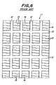
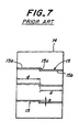
- a pneumatic tire having a tread pattern as shown in Figs. 6 and 7 of the accompanying drawings, in which a plurality of land portions, blocks 14 in the illustrated embodiment are defined in a tread portion 11 by a plurality of wide-width grooves, specifically main grooves 12 extending in a circumferential direction of the tire and lateral grooves 13 crossing with the main grooves 12 and a plurality of narrow-width sipes 15 extending substantially in an axial direction of the tire are formed in each of the blocks 14.
- all of these main grooves 12, lateral grooves 13 and sipes 15 extend in a radial direction of the tire, so that even if the tread portion 11 is worn in the running of the tire, the plane shape of each of the main groove 12, lateral groove 13, block 14 and sipe 15 is substantially unchangeable.
- an object of the invention to provide a pneumatic tire capable of effectively controlling the degradation of tire performances accompanied with the progress of the wearing in the tread portion and a vulcanisation mold usable for the production of such a pneumatic tire.
- a pneumatic tire comprising: a tread portion divided by a plurality of wide-width grooves into a plurality of land portions and provided on each of said land portions with a plurality of sipes, a sipe between two of said wide-width grooves corresponding to at least a part of said sipes comprising a pair of main portions extending substantially in an axial direction and being shifted in the circumferential direction relative to each other, and a link portion connecting opposed end portions of said main portions to each other and extending substantially in a circumferential direction, characterized by said pair of the main portions being inclined in opposite directions with respect to a radial direction to increase a mutual distance (L) between the main portions as the depth of the main portion increases along the entire depth of the sipe.
- L mutual distance
- the pair of the main portions constituting the sipe are inclined in opposite directions with respect to the radial direction so as to make the mutual distance L between the main portions larger as the depth of the main portion becomes deep and also the opposed end portions of the main portions are connected to each other through the link portion extending substantially in the circumferential direction, so that the opening ends of the main portions are separated away from each other in the circumferential direction accompanied with the advance of the wearing of the tread portion to gradually prolong the length of the opening end of the link portion connecting the main portions to each other or the total length of the opening ends of the sipe, whereby the scratching effect and drainage (water removal) property of the sipe are improved and the gripping force is generated based on the easiness of the movement through the reduction of surface area of the land portion to thereby effectively control the degradation of the steering stability on wet road and the braking property on wet road.
- the rigidity of the land portion in front and rear directions and lateral direction becomes gradually small, which offsets the increase of the rigidity in the front and rear directions and the lateral direction due to the decrease of the land portion height as previously mentioned to effectively control the degradation of the ride comfort against vibrations on dry road.
- a vulcanization mold for the production of a pneumatic tire, comprising: frame segments for forming wide-width grooves in a tread portion of the tire, a recess defined by said frame segments for forming a land portion in the tread portion, and a plurality of blades disposed in the recess for forming sipes in the land portion, in which a blade between two of said frame segments corresponding to at least a part of said blades comprises a pair of main segments extending substantially in an axial direction and being shifted in the circumferential direction relative to each other, and a link segment connecting opposed end portions of said main segments to each other and extending substantially in a circumferential direction, characterized by the pair of the main segments being inclined in opposite directions with respect to a radial direction so as to increase a mutual distance (M) between the main segments as the main segments protrude upward from the bottom of the recess along the entire height of the blade.
- M mutual distance
- the sipes can accurately and easily be formed in the tread portion.
- numeral 21 is a tread portion of a pneumatic tire 22 having improved snow-ice performances.
- the tread portion 21 is comprised of an outer rubber layer 23 located outward in the radial direction and contacting with a road surface and an inner rubber layer 24 located inward in the radial direction.
- the outer rubber layer 23 is made from a foamed rubber or rubber having many closed cells therein, while the inner rubber layer 24 is made from usual rubber (non-foamed rubber) having a Shore A hardness higher than that of the outer rubber layer.
- a volume ratio of the outer rubber layer 23 to the whole of the tread rubber is not less than 10% for improving the snow-ice performances.
- a plurality of rectangular blocks 31 as a land portion are defined by these wide-width grooves 30 in the tread portion 21.
- each of at least a part of these blocks 31 or all blocks 31 in the illustrated embodiment are formed one or more narrow-width sipes 35, three sipes 35 in the illustrated embodiment, whereby a plurality of the sipes 35 are formed in the block 31 as the land portion.
- the sipe 35 extends substantially in an axial direction of the pneumatic tire 22 and both ends thereof are opened to the main grooves 28. Further, the sipe 35 has the same depth D at any position and is somewhat shallower than a groove depth h of the main groove 28 and the lateral groove 29.
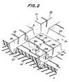
- a sipe 35 corresponding to at least a part of these sipes 35 is comprised of a pair of main portions 36a, 36b extending substantially in the axial direction, these main portions 36a, 36b being shifted with respect to each other in the circumferential direction, and a link portion 37 connecting opposed end portions of these main portions 36a, 36b, opposed inner end portions thereof in the illustrated embodiment to each other and extending substantially in the circumferential direction, and shows a step-like plan shape.
- the pair of the main portions 36a, 36b are inclined in opposite directions with respect to the radial direction so as to make the mutual distance L between the main portions 36a, 36b larger as the depth of the main portion becomes deep.
- the link portion 37 has a trapezoidal shape widening the width toward the bottom.
- the tread portion 21 of the pneumatic tire 22 in the illustrated embodiment is gradually worn during the running of the tire, since the main portions 36a, 36b of the sipe 35 are inclined at an enlarged state in the depth direction thereof and the opposed end portions of the main portions 36a, 36b are connected to each other through the link portion 37 extending substantially in the circumferential direction, the opening ends of the main portions 36a, 36b are separated away from each other in the circumferential direction to gradually prolong the length of the opening end of the link portion 37 connecting the main portions 36a, 36b as shown in Fig. 4. In other words, the total length of the opening end (edge length) of the sipe 35 is gradually prolonged.
- the drainage (water removal) property is improved and the block rigidity is appropriate to improve the steering stability on wet road and effectively control the degradation of the braking property on wet road.
- the rigidity of the block 31 in front and rear directions and lateral direction gradually decreases accompanied with the prolonging of the total length of the opening end of the sipe 35, which offsets the increase of the rigidity in front and rear directions and lateral direction due to the decrease of the block height to effectively control the degradation of the ride comfort against vibrations on dry road.
- the main portions 36a, 36b of the sipe 35 are inclined in opposite directions at the enlarged state toward the depth direction thereof, so that rubber between two adjacent sipes 35 in the circumferential direction becomes large in the moment of inertia of the section as compared with the conventional case of extending the sipe 15 in the radial direction (see Fig. 7), and hence the rigidity of the block 31 in front and rear directions and lateral direction is increased to a certain extent irrespective of the wearing degree, and also the ground contact pressure of the land portion is made uniform to improve the ground contacting property of the tread portion.
- the steering stability on dry road, steering stability on wet road and braking property on wet road of a new tire are improved and further snow-ice performances (steering stability on snow, braking property on ice) are improved over a full period of wearing and also the wear resistance is improved.
- numeral 41 is a vulcanization mold for the production of the pneumatic tire 22.
- the mold 41 has a tread forming face 42 for the formation of the tread portion 21 therein.
- the tread forming face 42 are disposed a plurality of main frame segments 43, four main frame segments 43 in the illustrated embodiment protruding inward from the face 42 and extending substantially in the circumferential direction and arranged at given intervals in the axial direction, and a plurality of lateral frame segments 44 crossing at right angles with the main frame segments 43 and extending in the axial direction and arranged at given intervals in the circumferential direction.
- main frame segments 43 and lateral frame segments 44 form plural frame segments 45 as a whole, in which the main frame segments 43 form main grooves 28 in the tread portion 21 of an uncured tire and the lateral frame segments 44 form lateral grooves 29. Furthermore, the tread forming face 42 is provided with a plurality of recesses 46 defined by these main frame segments 43 and lateral frame segments 44. These recesses 46 form blocks 31 in the tread portion 21 of the uncured tire.
- Numeral 50 is a blade for forming a sipe 35 in the outer surface of the block 31.
- One or more blades 50 are disposed in each of the recesses corresponding to at least a part of the recesses 46 or all recesses 46 in the illustrated embodiment, so that a plurality of blades 50 are arranged in the recesses 46 as a whole.
- Each of these blades 50 is provided on its outer end portion in the radial direction with an embedded portion 51 extending in the radial direction.
- the embedded portion 51 or a part of the blade 50 is embedded in the vulcanization mold 41.
- Numeral 52 is a sipe forming portion extending from the embedded portion 51 substantially inward in the radial direction, i.e.
- the sipe forming portion 52 protrudes inward from the bottom of the recess 46. Further, the sipe forming portion 52 extends substantially in the axial direction and contacts at both ends with the main frame segments 43, in which the height of the sipe forming portion is the same at any position and is somewhat lower than the height of the main frame segment 43 and lateral frame segment 44.
- a sipe forming portion of a blade 50 corresponding to at least a part of these blades 50 or each of all blades 50 in the illustrated embodiment comprises a pair of main segments 53a, 53b extending substantially in the axial direction, these main segments 53a, 53b being shifted with respect to each other in the circumferential direction, and a link segment 54 connecting opposed end portions of these main segments 53a, 53b, i.e. opposed inner end portions in the illustrated embodiment to each other and extending substantially in the circumferential direction, and shows a step-like plan shape.
- the pair of the main segments 53a, 53b are inclined in opposite directions with respect to the radial direction so as to make the mutual distance M between the main segments 53a, 53b larger as the main segments protrude upward from the bottom of the recess. That is, when the main segment 53a is inclined at one side with respect to the circumferential direction inward in the radial direction, the main segment 53b is inclined at the other side with respect to the circumferential direction inward in the radial direction, and hence the link segment 54 has a trapezoidal shape widening the width toward the bottom.
- the inclination angle of the main segment 53a, 53b with respect to the radial direction is too small, the degradation of the tire performances as mentioned above can not effectively be controlled, while when it is too large, it is difficult to take out the blades 50 from the cured tire after the vulcanization, so that the inclination angle is preferably within a range of 3-15 degrees.
- an uncured tire is first placed in the mold 41 and then a vulcanization medium of high temperature and high pressure is charged into an inside of a bladder (not shown) to push the uncured tire onto the tread forming face 42.
- a vulcanization medium of high temperature and high pressure is charged into an inside of a bladder (not shown) to push the uncured tire onto the tread forming face 42.
- the main frame segments 43, lateral frame segments 44 and sipe forming portions 52 of the blades 50 are pushed into the tread portion 21 of the uncured tire, whereby a plurality of main grooves 28 and a plurality of lateral grooves 29 are accurately and easily formed in the outer surface of the tread portion 21 and also sipes 35 are accurately and easily formed in the outer surfaces of the blocks 31 defined by these main grooves 28 and lateral grooves 29.
- the tread portion 21 has a two-layer structure comprised of the outer rubber layer 23 made from foamed rubber and the inner rubber layer 24 made from usual rubber (non-foamed rubber), but the whole of the tread portion 21 may be made from usual rubber in the invention.
- the land portion is the block 31 in the illustrated embodiment, the land portion may be a rib by omitting the lateral grooves.
- both ends of the sipe 35 are opened to the main grooves 28 in the above illustrated embodiments, but a sipe one end of which is terminated in the land portion or a sipe terminating both ends in the land portion may be used in the invention.
- the link portion 37 connects opposed inner ends of the main portions 36a, 36b to each other in the above illustrated embodiment, but it may connect opposed inner end parts of the main portions located somewhat outward from the inner ends thereof to each other in the invention.
- the main portions 36a, 36b may be bent in a wavy or zigzag form in the invention.
- a conventional tire having a tread pattern shown in Figs. 6 and 7 in which the sipe 15 extends along the radial direction (the opening shape is unchangeable even in the progress of the wearing) and has a length d of main portions 15a, 15b of 12 mm and a length e of a link portion 15c of 2 mm, and a test tire according to the invention having a tread pattern shown in Figs.
- the sipe 35 has a length f of main portions 36a, 36b of 12 mm and a length g of link portion 37 of 2 mm in a new tire and 5.5 mm at a point j separated from the surface of the block 31 by 0.7 times a height h of the main groove 28 (10 mm) in the depth direction.
- Each of these tires has a tire size of 205/65R15.
- the depth D of each of the sipes 15, 35 is 8 mm.
- the tire is mounted on a passenger car having a displacement of 2000 cc and thereafter various tests were made with respect to steering stability on dry road, ride comfort against vibrations on dry road, steering stability on wet road, braking property on wet road, steering stability on snow, braking property on ice and wear resistance.
- the test results are shown in Table 1.
- the term "worn state" in Table 1 means that the block is worn up to a distance corresponding to 70% of the depth of the main groove (i.e. point j).
- the steering stability on dry road and ride comfort against vibrations on dry road are evaluated by a professional driver's feeling when the passenger car is run on dry road, and the steering stability on wet road is evaluated by a professional driver's feeling when the passenger car is run on wet road prepared by spraying water on a test course, and the braking property on wet road is evaluated by an index representing a running distance when the passenger car running at a speed of 80 km/h on wet road is full-braked.
- the steering stability on snow is evaluated by a professional driver's feeling when the passenger car is run on a snow road
- the braking property on ice is evaluated by an index representing a running distance when the passenger car running at a speed of 20 km/h on a frozen road is full-braked
- the wear resistance is evaluated by an index representing an average value of the remaining depth of the wide-width groove measured at 10 places after the passenger car is run over a distance of 40,000 km.
- the steering stability on dry road, ride comfort against vibrations on dry road, steering stability on wet road and steering stability on snow are represented by a relative evaluation of 10 points when the new state of the conventional tire (control) is 5 points, in which ⁇ 0 is unchangeable, +2 is slightly good, +4 is good, -1 is slightly bad, -3 is bad and -5 is fairly bad.
- the braking property on wet road, braking property on ice and wear resistance are represented by an index value on the basis that the conventional tire is 100, in which the larger the index value, the better the property.
- the degradation of tire performances accompanied with the advance of the wearing of the tread portion can effectively be controlled.
Landscapes
- Engineering & Computer Science (AREA)
- Mechanical Engineering (AREA)
- Tires In General (AREA)
- Heating, Cooling, Or Curing Plastics Or The Like In General (AREA)
- Moulds For Moulding Plastics Or The Like (AREA)
Claims (10)
- Bandage pneumatique (22) comprenant : une partie de bande de roulement (21) divisée par plusieurs rainures de grande largeur (30) en plusieurs parties d'appui (31) et comportant sur chacune desdites parties d'appui plusieurs lamelles (35), une lamelle entre deux desdites rainures de grande largeur correspondant à au moins une partie desdites lamelles comprenant une paire de parties principales (36a, 36b) s'étendant pratiquement dans une direction axiale et décalées l'une par rapport à l'autre dans la direction circonférentielle, et une partie de liaison (37) reliant les parties d'extrémité opposées desdites parties principales et s'étendant pratiquement dans une direction circonférentielle, caractérisé en ce que ladite paire de parties principales (36a, 36b) est inclinée dans des directions opposées par rapport à une direction radiale pour accroítre une distance mutuelle (L) entre les parties principales (36a, 36b) lors d'un accroissement de la profondeur de la partie principale le long de l'ensemble de la profondeur de la lamelle.
- Bandage pneumatique selon la revendication 1, caractérisé en ce que chacune desdites parties principales (36a, 36b) est inclinée à un angle compris entre 3 et 15° par rapport à la direction radiale.
- Bandage pneumatique selon les revendications 1 ou 2, caractérisé en ce que les autres parties d'extrémité de chacune desdites parties principales (36a, 36b) de la lamelle sont ouvertes vers lesdites rainures de grande largeur (30).
- Bandage pneumatique selon l'une quelconque des revendications 1 à 3, caractérisé en ce que lesdites lamelles (35) ont une profondeur constante.
- Bandage pneumatique selon la revendication 4, caractérisé en ce que ladite profondeur constante desdites lamelles (35) correspond à environ 0,7 h, h étant une profondeur d'une rainure de grande largeur (30).
- Bandage pneumatique selon l'une quelconque des revendications 1 à 5, caractérisé en ce que ladite partie de bande de roulement (21) est composée d'une structure à deux couches comprenant une couche de caoutchouc moussé externe et une couche interne composée d'une couche de caoutchouc non moussé.
- Moule de vulcanisation (41) pour la production d'un bandage pneumatique (22), comprenant : des segments de cadre (45) pour former des rainures de grande largeur (30) dans une partie de bande de roulement (21) du bandage pneumatique, un évidement (46) défini par lesdits segments de cadre pour former une partie d'appui (31) dans la partie de bande de roulement et plusieurs lames (50) agencées dans l'évidement (46) pour former des lamelles (35) dans la partie d'appui, une lame entre deux desdits segments de cadre correspondant à au moins une partie desdites lames comprenant une paire de segments principaux (53a, 53b) s'étendant pratiquement dans une direction axiale et décalés les uns par rapport aux autres dans la direction circonférentielle, et un segment de liaison (54) reliant les parties d'extrémité opposées desdits segments principaux et s'étendant pratiquement dans une direction circonférentielle, caractérisé en ce que la paire de segments principaux (53a, 53b) est inclinée dans des directions opposées par rapport à une direction radiale, de sorte à accroítre une distance mutuelle (M) entre les segments principaux (53a, 53b) lors du débordement des segments principaux vers le haut à partir du fond de l'évidement, le long de l'ensemble de la hauteur de la lame.
- Moule de vulcanisation selon la revendication 7, caractérisé en ce que chacun des segments principaux (53a, 53b) est incliné à un angle de 3 à 15° par rapport à la direction radiale.
- Moule de vulcanisation selon les revendications 7 ou 8, caractérisé en ce que lesdits segments principaux (53a, 53b) de ladite lame (50) s'étendant dans la direction axiale pour contacter lesdits segments de cadre (45).
- Moule de vulcanisation selon l'une quelconque des revendications 7 à 9, caractérisé en ce que lesdites lames (50) ont une hauteur radiale constante.
Applications Claiming Priority (3)
| Application Number | Priority Date | Filing Date | Title |
|---|---|---|---|
| JP26241796A JP3636253B2 (ja) | 1996-09-11 | 1996-09-11 | 空気入りタイヤの加硫用金型 |
| JP262417/96 | 1996-09-11 | ||
| JP26241796 | 1996-09-11 |
Publications (3)
| Publication Number | Publication Date |
|---|---|
| EP0829381A2 EP0829381A2 (fr) | 1998-03-18 |
| EP0829381A3 EP0829381A3 (fr) | 1999-10-06 |
| EP0829381B1 true EP0829381B1 (fr) | 2002-12-04 |
Family
ID=17375501
Family Applications (1)
| Application Number | Title | Priority Date | Filing Date |
|---|---|---|---|
| EP97306970A Expired - Lifetime EP0829381B1 (fr) | 1996-09-11 | 1997-09-09 | Bandage pneumatique et moule de vulcanisation correspondant |
Country Status (5)
| Country | Link |
|---|---|
| US (1) | US5950700A (fr) |
| EP (1) | EP0829381B1 (fr) |
| JP (1) | JP3636253B2 (fr) |
| DE (1) | DE69717570T2 (fr) |
| ES (1) | ES2187729T3 (fr) |
Cited By (1)
| Publication number | Priority date | Publication date | Assignee | Title |
|---|---|---|---|---|
| WO2017167711A1 (fr) | 2016-03-30 | 2017-10-05 | Compagnie Generale Des Etablissements Michelin | Pneumatique comportant un bloc avec des incisions |
Families Citing this family (26)
| Publication number | Priority date | Publication date | Assignee | Title |
|---|---|---|---|---|
| US6427737B1 (en) * | 1998-04-22 | 2002-08-06 | Bridgestone Corporation | Pneumatic tire having at least four sipes |
| FI982379A7 (fi) * | 1998-06-10 | 1999-12-11 | Nokian Renkaat Oyj | Renkaan kulutuspinnan kuviopalojen rakenne, jossa kuviopalassa on yksi tai useampi hienoura, ja muotinosa tällaisten kuviopalojen muodostamiseksi |
| JP4255165B2 (ja) * | 1999-05-07 | 2009-04-15 | 株式会社ブリヂストン | 空気入りタイヤおよびその加硫用金型 |
| FR2801531A1 (fr) * | 1999-11-25 | 2001-06-01 | Michelin Soc Tech | Moule de bande de roulement |
| JP4165728B2 (ja) * | 2000-08-02 | 2008-10-15 | 東洋ゴム工業株式会社 | 空気入りタイヤ |
| US6826819B1 (en) * | 2000-11-01 | 2004-12-07 | Quality Mold, Inc. | Method for making a ventless tire mold |
| EP1215055B1 (fr) * | 2000-12-12 | 2006-04-05 | Continental Aktiengesellschaft | Bandage pneumatique pour véhicule, pourvu d'un profil de bande de roulement ayant des propriétés de traction sur neige et glace ameliorées |
| DE10101507A1 (de) * | 2001-01-12 | 2002-08-01 | Continental Ag | Fahrzeugreifen |
| DE10108595C1 (de) * | 2001-02-22 | 2002-11-28 | Continental Ag | Fahrzeugreifen |
| FR2826911A1 (fr) * | 2001-07-09 | 2003-01-10 | Michelin Soc Tech | Bande de roulement pourvue d'incisions |
| US7090735B2 (en) | 2001-08-06 | 2006-08-15 | Bridgestone/Firestone North American Tire, Llc | Method of compensating for residual aligning torque (RAT) |
| JP3963769B2 (ja) * | 2002-04-30 | 2007-08-22 | 横浜ゴム株式会社 | 空気入りタイヤ |
| JP4274355B2 (ja) * | 2003-04-09 | 2009-06-03 | 東洋ゴム工業株式会社 | 空気入りタイヤ |
| FR2888163B1 (fr) * | 2005-07-05 | 2007-09-14 | Michelin Soc Tech | Bande de roulement comportant une sculpture avec des incisions. |
| US7819153B2 (en) * | 2006-11-08 | 2010-10-26 | Bridgestone Americas Tire Operations, Llc | Tire including concave recesses in a circumferential tread |
| US20090000713A1 (en) * | 2007-06-27 | 2009-01-01 | Bridgestone Firestone North American Tire, Llc | Tire including segmented sipes |
| JP4715890B2 (ja) * | 2008-09-10 | 2011-07-06 | 横浜ゴム株式会社 | 空気入りタイヤ |
| US20100098568A1 (en) * | 2008-10-16 | 2010-04-22 | Adrian Marica | Mud pump systems for wellbore operations |
| FR2956354A1 (fr) * | 2010-02-12 | 2011-08-19 | Michelin Soc Tech | Pneumatique pour vehicules a deux roues comportant une bande de roulement presentant des incisions. |
| US9616716B2 (en) | 2011-12-14 | 2017-04-11 | Bridgestone Americas Tire Operations, Llc | Three dimensional sipe |
| FR2984226B1 (fr) * | 2011-12-16 | 2014-06-20 | Michelin Soc Tech | Methode de fabrication d'une bande de roulement pour pneumatique |
| DE102012110567A1 (de) * | 2012-11-05 | 2014-05-08 | Continental Reifen Deutschland Gmbh | Laufstreifenprofil eines Fahrzeugreifens |
| JP6062775B2 (ja) * | 2013-03-13 | 2017-01-18 | 住友ゴム工業株式会社 | タイヤ加硫用金型、タイヤ加硫方法および空気入りタイヤ |
| EP2813353A1 (fr) * | 2013-06-14 | 2014-12-17 | Compagnie Generale Des Etablissements Michelin | Élément de moulage comprenant des moyens de découpe pour mouler et vulcaniser la bande de roulement d'un pneu et procédé de moulage d'une bande de roulement d'un pneu utilisant ledit élément. |
| JP2016000575A (ja) * | 2014-06-11 | 2016-01-07 | 株式会社ブリヂストン | タイヤ |
| DE112020000331T5 (de) | 2019-02-22 | 2021-10-14 | The Yokohama Rubber Co., Ltd. | Luftreifen |
Family Cites Families (13)
| Publication number | Priority date | Publication date | Assignee | Title |
|---|---|---|---|---|
| US2779060A (en) * | 1953-05-13 | 1957-01-29 | Firestone Tire & Rubber Co | Tire mold |
| FR2302875A1 (fr) * | 1975-03-04 | 1976-10-01 | Michelin & Cie | Perfectionnements aux enveloppes de pneumatiques |
| JPS5998834A (ja) * | 1982-11-29 | 1984-06-07 | Yokohama Rubber Co Ltd:The | タイヤ成形用金型 |
| DE3324649A1 (de) * | 1983-07-08 | 1985-01-31 | Continental Gummi-Werke Ag, 3000 Hannover | Fahrzeugluftreifen |
| US5176765A (en) * | 1988-04-13 | 1993-01-05 | Bridgestone Corporation | Pneumatic tire having outer tread layer of foam rubber |
| FR2641501B1 (fr) * | 1989-01-10 | 1991-03-08 | Michelin & Cie | Bande de roulement pour pneumatique destine a des roulages hivernaux |
| JP2892030B2 (ja) * | 1989-03-20 | 1999-05-17 | 株式会社ブリヂストン | サイプで区切られたブロックを有する空気入りタイヤ |
| US5095963A (en) * | 1990-02-22 | 1992-03-17 | The Goodyear Tire & Rubber Company | Tire treads |
| IT1240295B (it) * | 1990-04-13 | 1993-12-07 | Pirelli | Stampo e metodo per la vulcanizzazione di pneumatici e metodo per fabbricare stampi |
| EP0540340B1 (fr) * | 1991-11-01 | 1996-08-28 | Bridgestone Corporation | Bandage pneumatique, moule de fabrication et procédé de fabrication |
| FR2683771B1 (fr) * | 1991-11-18 | 1994-01-07 | Michelin & Cie | Bande de roulement pourvue de rainures dont les parois sont munies d'incisions. |
| JP3366737B2 (ja) * | 1994-06-29 | 2003-01-14 | 株式会社ブリヂストン | 空気入りタイヤ |
| JP2774778B2 (ja) * | 1994-12-16 | 1998-07-09 | 住友ゴム工業株式会社 | 空気入りタイヤ |
-
1996
- 1996-09-11 JP JP26241796A patent/JP3636253B2/ja not_active Expired - Fee Related
-
1997
- 1997-09-09 DE DE69717570T patent/DE69717570T2/de not_active Expired - Lifetime
- 1997-09-09 ES ES97306970T patent/ES2187729T3/es not_active Expired - Lifetime
- 1997-09-09 EP EP97306970A patent/EP0829381B1/fr not_active Expired - Lifetime
- 1997-09-10 US US08/926,436 patent/US5950700A/en not_active Expired - Fee Related
Cited By (1)
| Publication number | Priority date | Publication date | Assignee | Title |
|---|---|---|---|---|
| WO2017167711A1 (fr) | 2016-03-30 | 2017-10-05 | Compagnie Generale Des Etablissements Michelin | Pneumatique comportant un bloc avec des incisions |
Also Published As
| Publication number | Publication date |
|---|---|
| US5950700A (en) | 1999-09-14 |
| ES2187729T3 (es) | 2003-06-16 |
| JPH1081113A (ja) | 1998-03-31 |
| DE69717570D1 (de) | 2003-01-16 |
| EP0829381A3 (fr) | 1999-10-06 |
| DE69717570T2 (de) | 2003-09-25 |
| JP3636253B2 (ja) | 2005-04-06 |
| EP0829381A2 (fr) | 1998-03-18 |
Similar Documents
| Publication | Publication Date | Title |
|---|---|---|
| US5950700A (en) | Pneumatic tire and vulcanization mold therefor | |
| US7637295B2 (en) | Pneumatic tire with tread including sipes having bent portions formed with zigzag shape with amplitude in radial direction | |
| EP1073562B1 (fr) | Bande de roulement avec incisions de structure tridimensionelle | |
| EP0342908B1 (fr) | Bandage pneumatique | |
| US4078596A (en) | Highly durable tread pattern of a rib type pneumatic tire | |
| EP0904960B1 (fr) | Bandage pneumatique sans crampons | |
| JP4316452B2 (ja) | 空気入りタイヤ | |
| JPH07215017A (ja) | スタッドレスタイヤ | |
| JP3702958B2 (ja) | 氷雪路用空気入りタイヤ | |
| JP3359000B2 (ja) | 空気入りタイヤ | |
| JP3883297B2 (ja) | 空気入りラジアルタイヤ | |
| JP4255165B2 (ja) | 空気入りタイヤおよびその加硫用金型 | |
| CN110709260B (zh) | 充气轮胎 | |
| JPH09188110A (ja) | 重荷重用空気入りラジアルタイヤ | |
| JP2006176055A (ja) | 空気入りタイヤ | |
| JP3415418B2 (ja) | 空気入りタイヤ | |
| JP4285609B2 (ja) | 空気入りタイヤ | |
| JP3273771B2 (ja) | 空気入りタイヤ | |
| JP2000190711A (ja) | 車の車輪用タイヤ及び車の車輪用タイヤのトレッドパターン内に雪の取り込みを増す方法 | |
| JP4285599B2 (ja) | 氷雪路用空気入りタイヤ | |
| JPS6218305A (ja) | タイヤの製造方法 | |
| JP2001322406A (ja) | 空気入りタイヤ | |
| JP3351894B2 (ja) | 重荷重用空気入りタイヤ | |
| JP3084231B2 (ja) | 空気入りタイヤ | |
| JP2006151230A (ja) | 空気入りタイヤ |
Legal Events
| Date | Code | Title | Description |
|---|---|---|---|
| PUAI | Public reference made under article 153(3) epc to a published international application that has entered the european phase |
Free format text: ORIGINAL CODE: 0009012 |
|
| AK | Designated contracting states |
Kind code of ref document: A2 Designated state(s): DE ES FR GB IT |
|
| PUAL | Search report despatched |
Free format text: ORIGINAL CODE: 0009013 |
|
| AK | Designated contracting states |
Kind code of ref document: A3 Designated state(s): AT BE CH DE DK ES FI FR GB GR IE IT LI LU MC NL PT SE |
|
| RIC1 | Information provided on ipc code assigned before grant |
Free format text: 6B 60C 11/12 A, 6B 29D 30/06 B, 6B 29C 33/42 B |
|
| 17P | Request for examination filed |
Effective date: 20000110 |
|
| AKX | Designation fees paid |
Free format text: DE ES FR GB IT |
|
| GRAG | Despatch of communication of intention to grant |
Free format text: ORIGINAL CODE: EPIDOS AGRA |
|
| 17Q | First examination report despatched |
Effective date: 20011214 |
|
| GRAG | Despatch of communication of intention to grant |
Free format text: ORIGINAL CODE: EPIDOS AGRA |
|
| GRAG | Despatch of communication of intention to grant |
Free format text: ORIGINAL CODE: EPIDOS AGRA |
|
| GRAH | Despatch of communication of intention to grant a patent |
Free format text: ORIGINAL CODE: EPIDOS IGRA |
|
| GRAH | Despatch of communication of intention to grant a patent |
Free format text: ORIGINAL CODE: EPIDOS IGRA |
|
| GRAA | (expected) grant |
Free format text: ORIGINAL CODE: 0009210 |
|
| AK | Designated contracting states |
Kind code of ref document: B1 Designated state(s): DE ES FR GB IT |
|
| REG | Reference to a national code |
Ref country code: GB Ref legal event code: FG4D |
|
| REF | Corresponds to: |
Ref document number: 69717570 Country of ref document: DE Date of ref document: 20030116 |
|
| ET | Fr: translation filed | ||
| REG | Reference to a national code |
Ref country code: ES Ref legal event code: FG2A Ref document number: 2187729 Country of ref document: ES Kind code of ref document: T3 |
|
| PLBE | No opposition filed within time limit |
Free format text: ORIGINAL CODE: 0009261 |
|
| STAA | Information on the status of an ep patent application or granted ep patent |
Free format text: STATUS: NO OPPOSITION FILED WITHIN TIME LIMIT |
|
| 26N | No opposition filed |
Effective date: 20030905 |
|
| PGFP | Annual fee paid to national office [announced via postgrant information from national office to epo] |
Ref country code: ES Payment date: 20090929 Year of fee payment: 13 |
|
| PGFP | Annual fee paid to national office [announced via postgrant information from national office to epo] |
Ref country code: GB Payment date: 20090909 Year of fee payment: 13 |
|
| PGFP | Annual fee paid to national office [announced via postgrant information from national office to epo] |
Ref country code: DE Payment date: 20090903 Year of fee payment: 13 |
|
| PGFP | Annual fee paid to national office [announced via postgrant information from national office to epo] |
Ref country code: IT Payment date: 20090916 Year of fee payment: 13 Ref country code: FR Payment date: 20091012 Year of fee payment: 13 |
|
| GBPC | Gb: european patent ceased through non-payment of renewal fee |
Effective date: 20100909 |
|
| PG25 | Lapsed in a contracting state [announced via postgrant information from national office to epo] |
Ref country code: IT Free format text: LAPSE BECAUSE OF NON-PAYMENT OF DUE FEES Effective date: 20100909 |
|
| REG | Reference to a national code |
Ref country code: FR Ref legal event code: ST Effective date: 20110531 |
|
| REG | Reference to a national code |
Ref country code: DE Ref legal event code: R119 Ref document number: 69717570 Country of ref document: DE Effective date: 20110401 |
|
| PG25 | Lapsed in a contracting state [announced via postgrant information from national office to epo] |
Ref country code: FR Free format text: LAPSE BECAUSE OF NON-PAYMENT OF DUE FEES Effective date: 20100930 Ref country code: DE Free format text: LAPSE BECAUSE OF NON-PAYMENT OF DUE FEES Effective date: 20110401 |
|
| PG25 | Lapsed in a contracting state [announced via postgrant information from national office to epo] |
Ref country code: GB Free format text: LAPSE BECAUSE OF NON-PAYMENT OF DUE FEES Effective date: 20100909 |
|
| REG | Reference to a national code |
Ref country code: ES Ref legal event code: FD2A Effective date: 20111019 |
|
| PG25 | Lapsed in a contracting state [announced via postgrant information from national office to epo] |
Ref country code: ES Free format text: LAPSE BECAUSE OF NON-PAYMENT OF DUE FEES Effective date: 20100910 |