EP0829726A1 - Procédé et dispositif pour enregistrer des structures de courant tridimensionnelles - Google Patents
Procédé et dispositif pour enregistrer des structures de courant tridimensionnelles Download PDFInfo
- Publication number
- EP0829726A1 EP0829726A1 EP97111404A EP97111404A EP0829726A1 EP 0829726 A1 EP0829726 A1 EP 0829726A1 EP 97111404 A EP97111404 A EP 97111404A EP 97111404 A EP97111404 A EP 97111404A EP 0829726 A1 EP0829726 A1 EP 0829726A1
- Authority
- EP
- European Patent Office
- Prior art keywords
- light
- light section
- section plane
- particle
- plane
- Prior art date
- Legal status (The legal status is an assumption and is not a legal conclusion. Google has not performed a legal analysis and makes no representation as to the accuracy of the status listed.)
- Granted
Links
Images

Classifications
-
- G—PHYSICS
- G01—MEASURING; TESTING
- G01P—MEASURING LINEAR OR ANGULAR SPEED, ACCELERATION, DECELERATION, OR SHOCK; INDICATING PRESENCE, ABSENCE, OR DIRECTION, OF MOVEMENT
- G01P5/00—Measuring speed of fluids, e.g. of air stream; Measuring speed of bodies relative to fluids, e.g. of ship, of aircraft
- G01P5/001—Full-field flow measurement, e.g. determining flow velocity and direction in a whole region at the same time, flow visualisation
Definitions
- the invention relates to a method for detecting 3-dimensional flow structures.
- the invention relates to a device for detecting 3-dimensional flow structures with a light source for generating a light section plane, a receiving device assigned to the light section plane for detecting scattered light that generates a particle when crossing the light section plane, and with an evaluation and control device.
- Flow anemometers for example laser Doppler anemometers, are generally known from the prior art, which allow a selective measurement of flow fields. Due to the fact that the measurements are only punctiform, these methods are very good time consuming. Whole-field methods are therefore indispensable for the simultaneous detection of spatial turbulence structures.
- the method with the features of claim 1 and the device with the features of claim 5 have the advantage that flow fields that have not previously been analyzable can also be detected in three dimensions. This is achieved in particular in that, in addition to a light section plane, further light section planes of different wavelengths parallel and spatially offset from each other. This multilayer arrangement of light section planes allows the determination of the third speed component without having to scan the flow field sequentially.
- the light for generating the light section planes is intensity-modulated in a time-dependent manner, for example with a Bragg cell.
- This intensity modulation can also be found in the scattered light of the moving particles (tracer particles) in the flow field. This enables the start, end point and direction of the scattering particles to be clearly identified on the image (arrow coding).
- a single light source for generating the light section planes, which emits light of different wavelengths, preferably lasers, a color splitter dividing the multicolored light into the individual wavelengths.
- a plurality of light sources preferably lasers, are provided, each having a different wavelength and each generating a light section plane.
- the recording devices assigned to the light section planes preferably include inexpensive CCD arrays which feed the recorded image to a computer for further processing.
- an adjustment device is assigned to each recording device, which permits precise focusing on the corresponding light section plane. This can further increase the quality of the measurement result.
- monochromators or interference filters must be connected upstream in the beam path of the CCD arrays in order to filter out scattered light from the unassigned light section planes.
- An alternative option is to set up a wide light section with continuous color variation (in the third dimension) and capture the scattered light with a color video camera. By choosing a suitable lens or by stopping down, a clear image of the entire light section width can be achieved.
- An intensive white light source or a white light laser with subsequent spectral decomposition (prism, grating) and light section optics can serve as the light source.
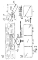
- a measuring device 1 comprises an Ar-ion laser 3, which generates light with the wavelengths 476.5 nm, 488 nm, and 514 nm.
- the light generated by the laser is fed to a color splitter 5, which splits the light into the individual colors or wavelengths.
- the disassembled light radiation is then fed to optics 7.1, 7.2 and 7.3, respectively, which generate so-called light section planes 9.
- the three light section planes 9.1, 9.2, 9.3 clearly differ in their wavelength.
- an objective 11 which bundles the light coming from the light section planes 9 to a beam splitter 13.
- the beam splitter 13 has the task of supplying the incoming light to the three receiving devices 15.
- the individual recording devices are focused on the respective cutting plane by means of adjusting devices 17.1, 17.2 and 17.3. A clear assignment of a receiving device 15 to a light section plane 9 can thus be achieved.
- the receiving device 15.1 is assigned to the light section plane 9.1, the receiving device 15.2 to the light section plane 9.2 and the receiving device 15.3 to the light section plane 9.3.
- a filter or a monochromator 19 which does not transmit light of undesired wavelength, is connected upstream of each receiving device 15.
- the undesired wavelengths are those which the other recording devices receive.
- the light beams from the light section planes are recorded in the recording devices by CCD arrays (not shown), which then transmit their image information to a computer 21, only shown schematically, for evaluation and further processing. in particular for digitization and storage.
- the light section planes 9 are generated parallel to one another and spatially offset, their longitudinal axis pointing in the direction of the main flow.
- particles which are also moved by the flow and are either already present naturally or are added specifically are used.
- light is reflected on each particle, which reaches the lens 11 as scattered light.
- Such scattered light can be detected by the three receiving devices 15 from the time of entry, for example, into the light section plane 9.1 to the exit from the light section plane 9.3.
- the images generated by the CCD arrays of the recording devices 15 thus supply a particle track 23, as is shown by way of example in FIG. 1b.
- the particle track 23.1 corresponds to the path in the light section plane 9.1, the particle track 23.2 to the path in the light section plane 9.2 and the particle track 23.3 to the path in the light section plane 9.3.
- the end of the particle track 23.1 highlighted in the drawing and the arrow head of the particle track 23.3 result from the temporal intensity modulation of the laser light (arrow coding) and accordingly also indicate whether the particle to be examined is present during the entire exposure time in the area of the light section planes. This means that the detected particle was at the beginning of the particle track 23.1 at the beginning of the exposure time and at the arrow head of the particle track 23.3 at the end of the exposure time.
- the computer 9 combines these three individual images 25.1, 25.2 and 25.3 for evaluation into a common image 27.
- the resulting entire particle track 23 now represents a direct image of the course of movement of the particle in the x / y plane.
- the speed components in the x and y directions v x and v y can be calculated with the aid of the aforementioned exposure time t b and an imaging scale f a of the entire optical system.
- a diagram is shown in FIG. 2a, in which the x / y path components S x and S y of the particle track 23 are shown.
- the calculation of the third speed component v z is determined indirectly on the basis of the residence time of the particle, for example in the middle light section plane 9.2.
- an additional time structure is imprinted on the particle track, for example by multiple exposure or modulation of the laser radiation. This then gives the time t bE2 shown in the diagram in FIG. 2a, that of the length of time of the particle in the Light section plane 9.2 corresponds.
- the duration of stay t bE2 can also be calculated by forming the ratio of the particle track 23.2 of the middle light section plane 9.2 to the total length of the Teliches track 23.
- the ratio of length of stay t bE2 and exposure time t b corresponds to the ratio of the length S E2z of the particle track 23.2 and the total length of the particle track 23.
- the prerequisite for this is, however, that the track is detected in all three light section planes and the beginning and end in the two outer ones Levels can be found.
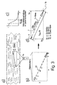
- FIG. 3 Another possibility for measuring the z component is shown in FIG. 3.
- a light section plane is asymmetrically intensity-modulated in the z-direction, the light intensity curve being indicated in the diagram shown in FIG. 3c. This is a half Gauss curve.
- intensity values of the particle track 23 can also be used to determine the z component, for example the intensity value when entering the middle light section plane and the intensity value when leaving the middle light section plane.
- a recording system with only one recording device for example a camera or a high-speed camera with high spatial resolution, can be used instead.
Landscapes
- Engineering & Computer Science (AREA)
- Aviation & Aerospace Engineering (AREA)
- Physics & Mathematics (AREA)
- General Physics & Mathematics (AREA)
- Investigating Or Analysing Materials By Optical Means (AREA)
- Length Measuring Devices By Optical Means (AREA)
Applications Claiming Priority (2)
| Application Number | Priority Date | Filing Date | Title |
|---|---|---|---|
| DE19635985 | 1996-09-05 | ||
| DE19635985 | 1996-09-05 |
Publications (2)
| Publication Number | Publication Date |
|---|---|
| EP0829726A1 true EP0829726A1 (fr) | 1998-03-18 |
| EP0829726B1 EP0829726B1 (fr) | 2003-04-16 |
Family
ID=7804671
Family Applications (1)
| Application Number | Title | Priority Date | Filing Date |
|---|---|---|---|
| EP97111404A Expired - Lifetime EP0829726B1 (fr) | 1996-09-05 | 1997-07-05 | Procédé et dispositif pour enregistrer des structures de courant tridimensionnelles |
Country Status (5)
| Country | Link |
|---|---|
| US (1) | US5883707A (fr) |
| EP (1) | EP0829726B1 (fr) |
| JP (1) | JPH1090294A (fr) |
| DE (2) | DE59709832D1 (fr) |
| ES (1) | ES2197267T3 (fr) |
Cited By (1)
| Publication number | Priority date | Publication date | Assignee | Title |
|---|---|---|---|---|
| ES2155331A1 (es) * | 1998-05-13 | 2001-05-01 | Univ Madrid Carlos Iii | Procedimiento de velocimetria por correlacion de imagenes de particulas con resolucion espacial menor que el tamaño de la ventana de interrogacion. |
Families Citing this family (27)
| Publication number | Priority date | Publication date | Assignee | Title |
|---|---|---|---|---|
| DE19926494C2 (de) * | 1999-06-10 | 2001-07-26 | Max Planck Gesellschaft | Verfahren und Vorrichtung zur Abbildung von mikroskopisch kleinen Teilchen |
| DE19928698A1 (de) * | 1999-06-23 | 2000-09-21 | Deutsch Zentr Luft & Raumfahrt | Vorrichtung zur Durchführung von PIV-Messungen |
| DE19963393C1 (de) | 1999-12-28 | 2001-07-26 | Bosch Gmbh Robert | Verfahren und Vorrichtung zur Analyse von Strömungen |
| DE10018305C2 (de) | 2000-04-13 | 2002-02-14 | Bosch Gmbh Robert | Verfahren und Vorrichtung zur Analyse von Strömungen |
| GB0010123D0 (en) * | 2000-04-27 | 2000-06-14 | Univ Nottingham | Planar light sheet anemometers |
| TW466346B (en) * | 2001-03-05 | 2001-12-01 | Nat Science Council | A low-cost continuous-wave-laser (CW laser) digital particle image velocimetry |
| US6542226B1 (en) | 2001-06-04 | 2003-04-01 | The United States Of America As Represented By The Administrator Of The National Aeronautics And Space Administration | Planar particle imaging and doppler velocimetry system and method |
| DE10312696B3 (de) * | 2003-03-21 | 2004-12-23 | Lavision Gmbh | Verfahren zur Bestimmung der Abbildungsgleichung für die Selbstkalibrierung in Bezug auf die Durchführung von Stereo-PIV-Verfahren |
| DE10343160B3 (de) | 2003-09-18 | 2005-05-25 | Lavision Gmbh | Verfahren zur Bestimmung eines dreidimensionalen Geschwindigkeitsfeldes in einem Volumen |
| DE102004057718B4 (de) * | 2004-11-26 | 2006-08-03 | Iav Gmbh Ingenieurgesellschaft Auto Und Verkehr | Vorrichtung zur Analyse von Strömungsvorgängen in der Kolbenmulde einer Brennkraftmaschine |
| GB2422193B (en) * | 2004-12-24 | 2008-07-16 | Campbell Scient Ltd | A weather measurement device for determining the speed in a first direction of hydrometeors |
| IL167932A (en) * | 2005-04-10 | 2012-03-29 | Israel Aerospace Ind Ltd | Systems and methods for detecting the position of an object passing through optical screens |
| DE102005056409B3 (de) * | 2005-11-26 | 2007-03-22 | Lavision Gmbh | Verfahren zur Bestimmung des Geschwindigkeitsfeldes in bewegten gasförmigen oder flüssigen Medien mit Hilfe von in das Medium eigebrachten Teilchen |
| US7772579B2 (en) * | 2006-05-18 | 2010-08-10 | Massachusetts Institute Of Technology | Method and apparatus for simultaneously measuring a three dimensional position of a particle in a flow |
| WO2007136818A2 (fr) * | 2006-05-18 | 2007-11-29 | Massachusetts Institute Of Technology | Procédé et appareil pour mesurer simultanément une position tridimensionnelle d'une particule dans un flux |
| US7821636B2 (en) * | 2006-05-18 | 2010-10-26 | Massachusetts Institute Of Technology | Method and apparatus for measuring a position of a particle in a flow |
| DE102006055746A1 (de) * | 2006-11-25 | 2008-05-29 | Lavision Gmbh | Verfahren zur Korrektur einer Volumenabbildungsgleichung zur Bestimmung eines Geschwindigkeitsfeldes von Teilchen in einem Volumen |
| US7920261B2 (en) | 2008-02-11 | 2011-04-05 | Massachusetts Institute Of Technology | Method and apparatus for detecting and discriminating particles in a fluid |
| TWI404894B (zh) * | 2009-12-22 | 2013-08-11 | Ind Tech Res Inst | 照明系統 |
| JP5810790B2 (ja) * | 2011-09-20 | 2015-11-11 | 富士通株式会社 | 可視化処理プログラム、可視化処理方法及び可視化処理装置 |
| CN103197095B (zh) * | 2013-04-08 | 2015-08-12 | 天津大学 | 分层同步三维粒子图像测速方法与装置 |
| CN103604945A (zh) * | 2013-10-25 | 2014-02-26 | 河海大学 | 一种三通道cmos同步偏振成像系统 |
| WO2016004810A1 (fr) * | 2014-07-08 | 2016-01-14 | 华东理工大学 | Procédé et dispositif de photographie à haute vitesse synchrone pour la rotation de microparticules dans un champ d'hydrocyclone |
| CN105974596B (zh) * | 2016-04-26 | 2018-07-31 | 南京理工大学 | 层析粒子图像测速的三维立体照明方法 |
| US10782311B2 (en) * | 2017-02-28 | 2020-09-22 | King Abdullah University Of Science And Technology | Rainbow particle imaging velocimetry for dense 3D fluid velocity imaging |
| US10186051B2 (en) | 2017-05-11 | 2019-01-22 | Dantec Dynamics A/S | Method and system for calibrating a velocimetry system |
| EP3683040A1 (fr) * | 2017-07-21 | 2020-07-22 | CL Schutzrechtsverwaltungs GmbH | Équipement de mesurage optique pour appareil de fabrication additive d'objets tridimensionnels |
Citations (3)
| Publication number | Priority date | Publication date | Assignee | Title |
|---|---|---|---|---|
| FR2582403A1 (fr) * | 1985-05-24 | 1986-11-28 | Saint Louis Inst Franco Allem | Procede pour la mesure simultanee de trois composantes de la vitesse par des methodes d'anemometrie laser par effet doppler |
| DE4408072A1 (de) * | 1994-02-01 | 1995-08-03 | Deutsche Forsch Luft Raumfahrt | Verwendung einer elektronischen Hochgeschwindigkeitskamera bei einem Verfahren zur Bestimmung von Strömungsgeschwindigkeiten in einer Strömung |
| US5491642A (en) * | 1993-12-03 | 1996-02-13 | United Technologies Corporation | CCD based particle image direction and zero velocity resolver |
Family Cites Families (16)
| Publication number | Priority date | Publication date | Assignee | Title |
|---|---|---|---|---|
| AU511464B2 (en) * | 1977-03-14 | 1980-08-21 | Berwind Corporation | Measuring characteristics of fluid materials |
| US4429995A (en) * | 1980-07-21 | 1984-02-07 | National Research Development Corporation | Two dimensinal flow analyzer |
| US4661913A (en) * | 1984-09-11 | 1987-04-28 | Becton, Dickinson And Company | Apparatus and method for the detection and classification of articles using flow cytometry techniques |
| DE3544347C1 (en) * | 1985-12-14 | 1987-06-04 | Deutsche Forsch Luft Raumfahrt | Method and device for rapid serial, and thus quasi-instantaneous punctiform measurement of local velocity components of a velocity field |
| US4919536A (en) * | 1988-06-06 | 1990-04-24 | Northrop Corporation | System for measuring velocity field of fluid flow utilizing a laser-doppler spectral image converter |
| US4989969A (en) * | 1988-06-30 | 1991-02-05 | Hughes Danbury Optical Systems, Inc. | Time of flight velocimeter |
| DE4118716A1 (de) * | 1990-07-16 | 1992-01-23 | Gerhart Schroff | Verfahren und anordnung zur optischen erfassung und auswertung von streulichtsignalen |
| SE468925B (sv) * | 1991-08-22 | 1993-04-19 | Gert Nilsson | En metod och en anordning foer att reducera den avstaandsberoende foerstaerkningsfaktorn vid maetning av stroemningsroerelser med en bildgivande laser-doppler teknik, i synnerhet vid maetning av blodperfusion genom en vaevnad |
| DE4200309A1 (de) * | 1992-01-09 | 1993-07-15 | Gerhard Arnold Dr Seiler | Vorrichtung und verfahren zur ermittlung der stroemung eines stroemungsmediums |
| DE4237440C1 (de) * | 1992-11-06 | 1994-03-10 | Deutsche Forsch Luft Raumfahrt | Vorrichtung zur dreidimensionalen Bestimmung von Strömungen |
| DE4313682C2 (de) * | 1993-04-22 | 1996-06-13 | Wolfgang Dipl Ing Frey | Verfahren zur visuellen Bestimmung und Messung des Abflusses von langsam und mit freiem Spiegel fließenden Flüssigkeiten unter Verwendung von Luftblasen als Meßmedium und eine Anordnung zur Durchführung des Verfahrens |
| DE4426956C2 (de) * | 1994-07-29 | 1996-12-05 | Deutsche Forsch Luft Raumfahrt | Verfahren zur Bestimmung der Geschwindigkeit einer Strömung |
| FR2725034B1 (fr) * | 1994-09-22 | 1997-01-03 | Sextant Avionique | Tete d'emission-reception pour anemometre doppler longitudinal |
| US5561515A (en) * | 1994-10-07 | 1996-10-01 | Tsi Incorporated | Apparatus for measuring particle sizes and velocities |
| DE4443069C2 (de) * | 1994-12-03 | 1997-01-16 | Deutsche Forsch Luft Raumfahrt | Verfahren zur Messung von Strömungsvektoren in Gasströmungen |
| DE29601159U1 (de) * | 1996-01-24 | 1996-05-02 | Färber, Adolf, 57399 Kirchhundem | Vorrichtung zur berührungslosen Überwachung der Durchsatzmenge eines strömenden Materials |
-
1997
- 1997-07-05 EP EP97111404A patent/EP0829726B1/fr not_active Expired - Lifetime
- 1997-07-05 ES ES97111404T patent/ES2197267T3/es not_active Expired - Lifetime
- 1997-07-05 DE DE59709832T patent/DE59709832D1/de not_active Expired - Fee Related
- 1997-08-30 DE DE19737933A patent/DE19737933A1/de not_active Withdrawn
- 1997-09-04 JP JP9239218A patent/JPH1090294A/ja active Pending
- 1997-09-05 US US08/924,804 patent/US5883707A/en not_active Expired - Fee Related
Patent Citations (3)
| Publication number | Priority date | Publication date | Assignee | Title |
|---|---|---|---|---|
| FR2582403A1 (fr) * | 1985-05-24 | 1986-11-28 | Saint Louis Inst Franco Allem | Procede pour la mesure simultanee de trois composantes de la vitesse par des methodes d'anemometrie laser par effet doppler |
| US5491642A (en) * | 1993-12-03 | 1996-02-13 | United Technologies Corporation | CCD based particle image direction and zero velocity resolver |
| DE4408072A1 (de) * | 1994-02-01 | 1995-08-03 | Deutsche Forsch Luft Raumfahrt | Verwendung einer elektronischen Hochgeschwindigkeitskamera bei einem Verfahren zur Bestimmung von Strömungsgeschwindigkeiten in einer Strömung |
Cited By (1)
| Publication number | Priority date | Publication date | Assignee | Title |
|---|---|---|---|---|
| ES2155331A1 (es) * | 1998-05-13 | 2001-05-01 | Univ Madrid Carlos Iii | Procedimiento de velocimetria por correlacion de imagenes de particulas con resolucion espacial menor que el tamaño de la ventana de interrogacion. |
Also Published As
| Publication number | Publication date |
|---|---|
| JPH1090294A (ja) | 1998-04-10 |
| EP0829726B1 (fr) | 2003-04-16 |
| DE59709832D1 (de) | 2003-05-22 |
| ES2197267T3 (es) | 2004-01-01 |
| DE19737933A1 (de) | 1998-03-12 |
| US5883707A (en) | 1999-03-16 |
Similar Documents
| Publication | Publication Date | Title |
|---|---|---|
| EP0829726B1 (fr) | Procédé et dispositif pour enregistrer des structures de courant tridimensionnelles | |
| EP0419936B1 (fr) | Procédé et dispositif pour la détection de phase de rayonnement notamment de rayonnement lumineux | |
| DE69319528T2 (de) | Konfokales Rastermikroskop mit kontinuierlicher Anzeige | |
| DE69225107T2 (de) | Teilchenanalysator | |
| DE69328986T2 (de) | Konfokales Rastermikroskop | |
| DE112015000627B4 (de) | Mikrospektroskopische Vorrichtung | |
| DE102010049672B3 (de) | Laser-Doppler-Linien-Distanzsensor zur dreidimensionalen Formvermessung bewegter Festkörper | |
| DE68908094T2 (de) | Teilchenmessvorrichtung. | |
| DE19912500A1 (de) | Verfahren und Vorrichtung zum Bestimmen von Eigenschaften einer laufenden Materialbahn | |
| EP1542051B1 (fr) | Procédé et système pour séparer des longueurs d'onde dans un microscope à balayage | |
| DE60036467T2 (de) | Verfahren und vorrichtung zur dopplergeschwindigkeitsmessung | |
| EP1181561B1 (fr) | Procede et dispositif pour analyser des ecoulements | |
| EP0307668A2 (fr) | Procédé et dispositif pour mesurer la vitesse d'écoulement d'un fluide dans des tunnels aérodynamiques | |
| CH629603A5 (de) | Bilduebertragungseinrichtung zur untersuchung von unzugaenglichen partien eines objektes. | |
| DE3116671A1 (de) | Instrument zum automatischen bestimmen der kennwerte eines optischen systems | |
| DE10056329B4 (de) | Optisches Abstandsmeßverfahren und Abstandssensor | |
| DE3712153C1 (de) | Verfahren zur Messung von Stroemungsvektoren in Gasstroemungen | |
| DE102022202778B4 (de) | System und Verfahren zur konfokal-chromatischen Linienabstandsmessung | |
| DE102006015170B4 (de) | Verfahren und Anordnung zur Erzeugung eines vergrößerten Messvolumens zur Bestimmung der Struktur und/oder Spulgeschwindigkeit textiler Fasern auf Basis der Laser-Doppler-Anemometrie | |
| DE4027328B4 (de) | 3D-Kamera zur Erfassung von Oberflächenstrukturen, insbesondere für zahnmedizinische Zwecke | |
| EP0260385B1 (fr) | Dispositif pour mesurer des vecteurs d'écoulement dans des écoulements de gaz | |
| DE102007063355B4 (de) | Verfahren zur optischen Messung von Geschwindigkeiten nach dem Ortsfrequenzfilterverfahren und Sensor zur optischen Messung von Geschwindigkeiten | |
| DE19856400B4 (de) | Verfahren und Vorrichtung zur direkten Phasenmessung von Strahlung | |
| DE3106025A1 (de) | Verfahren und vorrichtung zur schnellen messung oertlicher geschwindigkeitskomponenten in einem geschwindigkeitsfeld | |
| DE102004020881A1 (de) | Verfahren und Vorrichtung zum geometrischen Kalibrieren von optoelektronischen Messbildkameras |
Legal Events
| Date | Code | Title | Description |
|---|---|---|---|
| PUAI | Public reference made under article 153(3) epc to a published international application that has entered the european phase |
Free format text: ORIGINAL CODE: 0009012 |
|
| AK | Designated contracting states |
Kind code of ref document: A1 Designated state(s): CH DE ES FR GB IT LI SE |
|
| 17P | Request for examination filed |
Effective date: 19980918 |
|
| AKX | Designation fees paid |
Free format text: CH DE ES FR GB IT LI SE |
|
| RBV | Designated contracting states (corrected) |
Designated state(s): CH DE ES FR GB IT LI SE |
|
| 17Q | First examination report despatched |
Effective date: 20011213 |
|
| GRAG | Despatch of communication of intention to grant |
Free format text: ORIGINAL CODE: EPIDOS AGRA |
|
| GRAG | Despatch of communication of intention to grant |
Free format text: ORIGINAL CODE: EPIDOS AGRA |
|
| GRAH | Despatch of communication of intention to grant a patent |
Free format text: ORIGINAL CODE: EPIDOS IGRA |
|
| GRAH | Despatch of communication of intention to grant a patent |
Free format text: ORIGINAL CODE: EPIDOS IGRA |
|
| GRAA | (expected) grant |
Free format text: ORIGINAL CODE: 0009210 |
|
| AK | Designated contracting states |
Designated state(s): CH DE ES FR GB IT LI SE |
|
| REG | Reference to a national code |
Ref country code: GB Ref legal event code: FG4D Free format text: NOT ENGLISH |
|
| REG | Reference to a national code |
Ref country code: CH Ref legal event code: EP |
|
| REF | Corresponds to: |
Ref document number: 59709832 Country of ref document: DE Date of ref document: 20030522 Kind code of ref document: P |
|
| PG25 | Lapsed in a contracting state [announced via postgrant information from national office to epo] |
Ref country code: SE Free format text: LAPSE BECAUSE OF FAILURE TO SUBMIT A TRANSLATION OF THE DESCRIPTION OR TO PAY THE FEE WITHIN THE PRESCRIBED TIME-LIMIT Effective date: 20030716 |
|
| PG25 | Lapsed in a contracting state [announced via postgrant information from national office to epo] |
Ref country code: LI Free format text: LAPSE BECAUSE OF NON-PAYMENT OF DUE FEES Effective date: 20030731 Ref country code: CH Free format text: LAPSE BECAUSE OF NON-PAYMENT OF DUE FEES Effective date: 20030731 |
|
| GBT | Gb: translation of ep patent filed (gb section 77(6)(a)/1977) | ||
| REG | Reference to a national code |
Ref country code: ES Ref legal event code: FG2A Ref document number: 2197267 Country of ref document: ES Kind code of ref document: T3 |
|
| ET | Fr: translation filed | ||
| PLBE | No opposition filed within time limit |
Free format text: ORIGINAL CODE: 0009261 |
|
| STAA | Information on the status of an ep patent application or granted ep patent |
Free format text: STATUS: NO OPPOSITION FILED WITHIN TIME LIMIT |
|
| REG | Reference to a national code |
Ref country code: CH Ref legal event code: PL |
|
| 26N | No opposition filed |
Effective date: 20040119 |
|
| PGFP | Annual fee paid to national office [announced via postgrant information from national office to epo] |
Ref country code: DE Payment date: 20050916 Year of fee payment: 9 |
|
| PGFP | Annual fee paid to national office [announced via postgrant information from national office to epo] |
Ref country code: FR Payment date: 20060719 Year of fee payment: 10 |
|
| PGFP | Annual fee paid to national office [announced via postgrant information from national office to epo] |
Ref country code: GB Payment date: 20060721 Year of fee payment: 10 |
|
| PGFP | Annual fee paid to national office [announced via postgrant information from national office to epo] |
Ref country code: ES Payment date: 20060724 Year of fee payment: 10 |
|
| PGFP | Annual fee paid to national office [announced via postgrant information from national office to epo] |
Ref country code: IT Payment date: 20060731 Year of fee payment: 10 |
|
| PG25 | Lapsed in a contracting state [announced via postgrant information from national office to epo] |
Ref country code: DE Free format text: LAPSE BECAUSE OF NON-PAYMENT OF DUE FEES Effective date: 20070201 |
|
| GBPC | Gb: european patent ceased through non-payment of renewal fee |
Effective date: 20070705 |
|
| PG25 | Lapsed in a contracting state [announced via postgrant information from national office to epo] |
Ref country code: GB Free format text: LAPSE BECAUSE OF NON-PAYMENT OF DUE FEES Effective date: 20070705 |
|
| REG | Reference to a national code |
Ref country code: FR Ref legal event code: ST Effective date: 20080331 |
|
| PG25 | Lapsed in a contracting state [announced via postgrant information from national office to epo] |
Ref country code: FR Free format text: LAPSE BECAUSE OF NON-PAYMENT OF DUE FEES Effective date: 20070731 |
|
| REG | Reference to a national code |
Ref country code: ES Ref legal event code: FD2A Effective date: 20070706 |
|
| PG25 | Lapsed in a contracting state [announced via postgrant information from national office to epo] |
Ref country code: ES Free format text: LAPSE BECAUSE OF NON-PAYMENT OF DUE FEES Effective date: 20070706 |
|
| PG25 | Lapsed in a contracting state [announced via postgrant information from national office to epo] |
Ref country code: IT Free format text: LAPSE BECAUSE OF NON-PAYMENT OF DUE FEES Effective date: 20070705 |