EP0829736A2 - Procédé de mesure des distorsions de champ magnétique terrestre et capteur d'objet pour la mise en oeuvre du procédé - Google Patents
Procédé de mesure des distorsions de champ magnétique terrestre et capteur d'objet pour la mise en oeuvre du procédé Download PDFInfo
- Publication number
- EP0829736A2 EP0829736A2 EP97115300A EP97115300A EP0829736A2 EP 0829736 A2 EP0829736 A2 EP 0829736A2 EP 97115300 A EP97115300 A EP 97115300A EP 97115300 A EP97115300 A EP 97115300A EP 0829736 A2 EP0829736 A2 EP 0829736A2
- Authority
- EP
- European Patent Office
- Prior art keywords
- sensor
- magnetic field
- earth
- component
- measuring
- Prior art date
- Legal status (The legal status is an assumption and is not a legal conclusion. Google has not performed a legal analysis and makes no representation as to the accuracy of the status listed.)
- Withdrawn
Links
Images


Classifications
-
- G—PHYSICS
- G01—MEASURING; TESTING
- G01V—GEOPHYSICS; GRAVITATIONAL MEASUREMENTS; DETECTING MASSES OR OBJECTS; TAGS
- G01V3/00—Electric or magnetic prospecting or detecting; Measuring magnetic field characteristics of the earth, e.g. declination, deviation
- G01V3/08—Electric or magnetic prospecting or detecting; Measuring magnetic field characteristics of the earth, e.g. declination, deviation operating with magnetic or electric fields produced or modified by objects or geological structures or by detecting devices
- G01V3/087—Electric or magnetic prospecting or detecting; Measuring magnetic field characteristics of the earth, e.g. declination, deviation operating with magnetic or electric fields produced or modified by objects or geological structures or by detecting devices the earth magnetic field being modified by the objects or geological structures
Definitions
- the invention relates to a method according to the preamble of claim 1 and to an object sensor for performing this method.
- Sensors for the earth's magnetic field are known. They are mainly used to determine distortions in this field due to the presence of ferromagnetic objects.
- Förster in Z. Metallischen , 46 (1955) page 358ff describes a probe for measuring magnetic fields, which is used, among other things, to measure distortions of the earth's magnetic field.
- Förster shows how the described sensor measures the distortion of the earth's magnetic field emanating from underground iron parts and how these iron parts can be located in this way.
- sensors for measuring the distortion of the earth's magnetic field are generally used to detect or determine iron-containing or ferromagnetic objects that are in the vicinity of the probe. Because, due to the ferromagnetic material in the objects, the Field lines of the earth's magnetic field are compressed, and this results in a local maximum of the earth's magnetic field in the direction of the object. This effect is very well suited, for example, to probes for the detection of iron or parts of iron that are buried in walls, for traffic counting, for switching traffic lights, for firing anti-tank mines when such vehicles approach, etc.
- Another application for such a sensor is the detection of whether parked vehicles or containers are in a certain coverage zone.
- This application can be used, for example, for the management of parking lots or parking garages, as described, for example, in European Patent Application No. 92 913 669.5 (Schick).
- Another method to determine whether a ferromagnetic object is in the vicinity of the sensor is to measure the gradient of the earth's magnetic field (see Förster page 362). This measurement can be used for the location tasks of ferrous objects. This takes advantage of the fact that the earth's magnetic field is homogeneous in its natural state, which means that the density of the field lines is very constant. If a ferromagnetic body is introduced into this field, the homogeneity of the field is disturbed, since there is a field line compression in the center of the body and a corresponding thinning at its edge. This results in a gradient of the field distribution, which deviates from its natural value of almost zero and can be determined.
- the present invention is therefore based on the object of overcoming the above-mentioned disadvantages of the conventional sensors. According to the invention, this is achieved by combining the features of the characterizing part of claim 1.
- the invention is essentially based on the knowledge that the disadvantages of the sensors according to the prior art described above can best be remedied by using more than just one component of the earth's magnetic field for evaluation, so that the field distortions are unambiguously To be able to assign coverage by the body to be determined.
- a size ratio of the Dimensions of a maximum of 1: 2, preferably a maximum of 1: 4, in particular a maximum of 1: 8, can be understood.
- a physical quantity derived from a component to be measured can, for example, preferably be the absolute value of the gradient of the Z component of the field strength, but also the combination of the Z component with a horizontal component.
- the storage of a predetermined state makes it possible to determine practically three states, namely the presence of a moving and that of an immovable object and the absence of a magnetic field disturbance (idle state).
- the measure according to claim 2 will be used in most cases, because in the method according to the invention, as in the prior art described above according to Petersen et al., A small distance results in better detectability of the objects, but in the case of the invention without the above disadvantages described. If the expression "small in comparison " is used in this context, it should be understood to mean a distance which is a maximum of two hundred times, preferably a maximum of 100 times, in particular a maximum of fifty times, of the dimensions of the sensor.
- the accuracy can be further improved if the procedure is as claimed in claim 4, because each of the sensors is thus assigned a specific task and it can therefore be optimized more easily. If necessary, this can even simplify the evaluation circuit.
- an object sensor for performing the method according to the invention has the features of claim 7.
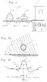
- a cable-like sensor 20a is laid on the street floor on a street 31 with traffic in both directions. The purpose of this is to determine the ferromagnetic bodies of vehicles 1a, 1b.
- this sensor 20a designed as a sensor cable will have a plurality of sensors 20b at predetermined distances from one another.
- the transducers 20b are individually addressable and are at a distance g from the underside of the vehicles 1a, 1b to be ascertained, which are generally between 20 and 30 cm and will usually not exceed 40 cm.
- the sensors 20b are relatively small, the distance g preferably being a maximum of two hundred times, preferably a maximum of 100 times, in particular a maximum of fifty times, of the dimensions of the sensor 20b.
- the size of the measuring transducers 20b should be compared to the vehicle to be determined 1a or 1b should be as small as possible, especially since FIGS. 3b and 3c will show that the local measurement signals along a vehicle are extremely different and that if the dimensions were too large, the individual signal forms would overlap with a corresponding location error, however, the size ratio of the dimensions of the measuring transducer 20b to those of the object in the context of the invention can preferably be at most 1: 2, preferably at most 1: 4, in particular at most 1: 8. Even smaller ratios, such as a maximum of 1:20, 1:50 or even 1: 100 are even cheaper. Depending on the object to be determined for which the sensor is to be designed, size ratios of 1: 200 to 1: 500 are also possible.
- the cable 20c itself is designed as a bus, which is connected to an evaluation device 32.
- This evaluation device 32 comprises, in a manner known per se in the case of sensor cables, an interrogation unit 33 which is controlled by an addressing unit 34 in order to interrogate the measured values of the individual transducers 20a.
- each transmitter 20b has an address assigned to it.
- the different impedance along the sensor cable 20c is used for addressing the individual transducers 20b, as was proposed in US-A-5,450,072, the content of which is to be regarded as disclosed here by reference. It may even be possible to use several, e.g. two, to interrogate sensors 20b at the same time, which can be expedient for traffic in both directions, in particular with a single sensor cable 20c.
- the measured value transmitters can be addressed in the manner described enables the measured value transmitter 20b which emits the measurement signal to be identified, so that it is clear whether the detected vehicle is now traveling in one direction or in the other direction.
- the design as a sensor cable with a large number of sensors arranged at intervals means that the distance g essentially determines the quality of the measurement, since sensors that are further away from the surface area covered by the vehicle will have a larger effective distance from the vehicle 1a or 1b as direct lying below this. Training as a sensor cable, on the other hand, ensures that at least one sensor comes under the vehicle 1a or 1b.
- the output of the query unit 33 is at an evaluation device 35, expediently with a memory, which is connected to an output unit 36, such as a monitor, a printer or another display device, the circuit used in the aforementioned US also being used here advantageously -A-5,450,072 is proposed.
- FIG. 2a shows the effect which is caused by a ferromagnetic body 1 in a magnetic field, for example in the earth's magnetic field.
- Its field lines 2 are namely compressed in the magnetic body 1, which in the example is a hollow tube.
- the field lines 2 are homogeneous in an area undisturbed by the body 1, as can be seen from FIG. 2a, and the field line density is constant in this area.
- the field lines 2 are at an inclination angle I, which is formed between a horizontal plane H and the field line direction 2a.
- the field strength corresponds to the field line density 3 shown in FIG. 2b.
- the curve shape of the field strength under the symmetrical body 1 would also be symmetrical. However, since the inclination angle I is less than 90 ° in the example in FIG. 2a, the curve shape is somewhat distorted and asymmetrical. The course of the field strength clearly shows that the curve first drops from the natural value N, which results in a field strength depression. Then it rises again to return to the level of the natural value N at points 4a and 4b, whereupon it rises to a maximum value 5.
- Rectangular curve 7 in FIG. 2b shows such a signal derived from exceeding threshold value 6 as is essentially emitted by a detector according to the prior art. It can also be seen that the location at which the object is recognized by the probe is offset by an amount n from the position of the tube 1 in FIG Object 1 will depend. This amount n leads to a location error which, depending on the application, can have a disruptive effect.
- FIG. 3a to 3c show such a real situation as the earth's magnetic field behaves in the near field of a vehicle 1.
- FIG. 3b shows the field strength curve as measured by a magnetic field probe 20 which is located approximately 10 cm below the vehicle 1.
- 3c shows the same measured values in a three-dimensional representation.
- the field strength values of the Z component of the earth's magnetic field vector are entered on the Z axis. In the present case, these are approximately 400 mG. 3c, the overlap zone 27 is drawn in obliquely above and below the measurement signal curves by the inclination angle I (cf. FIG. 3a).
- the effect brought about by vehicle 1 is significant in comparison to the natural field strength N, although the individual measurement signal curves are due to the fine structure of vehicle 1, that is to say due to the different presence of ferromagnetic parts thereof, over the length of the vehicle 1 are very different.
- the field line concentration in the north of the vehicle 1 in FIGS.
- FIGS. 3b and 3c the field course has been shifted to the north (left) as expected. However, this can be compensated for by placing a sensor to the south.
- the greater difficulties in evaluating the measurements for recognizing the vehicle 1 arise from field depressions which are located within the coverage zone 27. As can be seen from the example of FIGS. 3b and 3c, such a field depression 29 occurs approximately in the middle of the vehicle 1.
- This central field depression 29 comes about as follows:
- the field strength in the area of the front wheels rises to more than twice the natural value N.
- the attraction of the field lines from the magnetic centers of gravity at these two opposite ends of the vehicle 1 then cause them to thin out in the middle.
- the field lines are concentrated on the sides by body parts. The result, as can be seen in FIG. 3b, is a field strength value under the vehicle that even falls below the natural value N.
- FIG. 4a shows the measurements according to FIG. 3 in the form of lines of the same field strength. It can be seen that, starting from the natural field strength N, in a part of the coverage zone 27, the field strength increases in the front and rear area of the vehicle and on its north side (left in FIG. 4a). On the south side (on the right in Fig. 4a), however, and in the middle of the vehicle there is a depression d or 29 of the field strength below the natural value N.
- those areas 30a are shown hatched, in which the field strength is at least 100 mG above the natural value N.
- a sensor with a fixed threshold value (6 in FIG. 2b) would recognize the vehicle in such a region 30a.
- FIG. 4d illustrates in hatched areas 30b a preferred quantity derived from the field strength, namely the absolute value of the gradient of the Z component of the field strength. You can see that this size has large values in the problematic area, namely in the middle of the vehicle.
- the areas 30b hatched in FIG. 4d all have high values for the physical quantity derived for them. It can thus be seen from FIGS. 4b, 4c and 4d that none of the three physical variables shown in the example each result in themselves in a homogeneous coverage zone with sufficient detection reliability.
- FIG. 4e shows a preferred embodiment of the method according to the invention
- the measurements according to FIGS. 4b and 4d complementing one another and an OR combination (30a OR 30b) of exceeding a fixed threshold value in one of the differently hatched areas 30a and 30b on the one hand of the Z component (in FIG. 4b 100 mGauss above the natural value N) and on the other hand the absolute value of the gradient (FIG. 4d) can be used for evaluating the measurement.
- the absolute value of the gradient another suitable derived quantity or property of the vector of the earth's magnetic field can be used.
- This can be particularly advantageous in geographical latitudes where the inclination angle I is very small.
- a particularly advantageous embodiment is obtained when a plurality of measuring probes 20b are arranged on a sensor cable 20c (FIG. 1), the signals of which are processed in an evaluation computer 32 to inform whether vehicles are present in the area of the sensor cable 20c, and if so, in which locations.
- the embodiment as a sensor cable includes the advantage that the entire field profile of one or more properties of the earth's magnetic field can be used over a certain distance to evaluate the signals for object detection.
- this training represents a separate, advantageous and inventive idea, also independent of the measurement of at least two components of the earth's magnetic field.
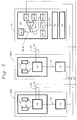
- FIG. 5 shows a possible circuit and the structure of a preferred object sensor according to the invention.
- the example of FIG. 5 is based on a probe according to Förster et al. from, which, as described in the article cited at the beginning, both as a field probe, can also be used as a field gradient probe, for example by controlling two coils as magnetically sensitive elements (see 41) in the same direction (Förster, p. 359, fig. 4 for field strength measurement, p. 360, fig. 7 for differential field measurement).
- the Z component and its gradients can be measured by two adjacent sensors, the signal difference of which gives a signal that is proportional to the field strength gradient, whereas each value is proportional to the field strength of a component.
- a type of probe which, depending on its external wiring, can either measure a component of the earth's magnetic field or its gradient.
- a probe 40 which can be evaluated twice, consists of two magnetically sensitive elements 41 and 41 '. These can be Förster coils, but they can also be the magnetically sensitive components of a bridge circuit that are arranged at a certain distance from one another, for example, two Hall probes that are as similar as possible could be used as magnetically sensitive elements 41 and 41 ' be arranged at a certain distance from each other.
- the evaluation unit 42 of FIG. 5 consists of a circuit which - based on the signals of the two magnetically sensitive Elements 41 and 41 '- at their outputs 43 generates a signal which is proportional to a main component of the field strength, and a second signal at their outputs 44 which is proportional to the field strength gradient.
- This can be a combined control and evaluation circuit according to Förster et al. ( Figures 4 and 7, pp. 359 and 360), or a bridge circuit according to Schintag et al. with multiple evaluation. Furthermore, it can also simply be a circuit which converts the signals from two probes 41 and 41 ', such as Hall probes, once into a differential signal for the gradient and once into an averaged sum signal for the field strength, be it one after the other ( sequentially) or in parallel.
- the field strength signals and the difference signals of the field strength according to FIG. 5 are fed in parallel (OR operation) to a field strength conductor 45 and a field strength difference conductor 45 ', which sends the corresponding signals from the measuring sensors 20b and 20b' to a central evaluation unit 47 (corresponding to 32 in FIG 1) leads.
- This has a storage element 46 into which the data from the signal conductors 45 and 45 'after an analog / digital conversion within a, e.g. with the memory 46 structurally combined analog / digital converter.
- This analog / digital converter is in each case directly connected to the inputs of the signal conductors 45, 45 'in the evaluation and storage stage 46 and 47 and is either formed directly by stages 46.1, 46.2 or these latter stages (if necessary additionally) provide intermediate memories for the Lines 45, 45 'represent incoming signal.
- the output of stages 46.1, 46.2 is optionally connected to a comparison stage 46.3, which determines the given ratio.
- This input circuit which is generally replaced by software, is followed by two memory blocks 46.4, 46.5, which can be selectively and alternately activated by closing or opening a (changeover) switch S.
- the leading to switch S. and line 46.8 connected to the outputs of stages 46.1 to 46.3 is shown here as a simple line, but in fact, for example, a bus which brings the output signals of input stages 46.1 to 46.3 separately to switch S or to the respective memory block 46.4 or 46.5.
- the one memory 46.4 is only switched to active in a learning phase, generally when the sensor is installed for the first time at a predetermined location, by means of the switch S.
- the signals of the input stages 46.1, 46.2 and / or the comparison stage 46.3 are in an idle state (e.g. Parking space not occupied or Do not drive on the street ) stored as reference signals. Then it is Learning process completed, and the switch S can accordingly switch to the other memory block 46.5. Since the learning process will generally only have to be carried out once at the beginning, a switch can also be provided instead of the switch S, which only supplies the input signals to the learning memory 46.4 and then to the operating memory 46.5 during a certain initial time after the sensor has been started up.
- a new learning phase can optionally be provided for re-calibration or in the event of operational changes if there is an arbitrary switching option, such as with the switch S.
- Another possibility would be to provide the learning memory 46.4 with a statistical program in order to statistically determine which signal combinations are probably the idle signal and which are the signals Busy can be seen. For example, there could be a higher frequency of idle states on a street in post-operation than during the day, and when the time is fed in, the input signal combination for the idle state could be determined statistically from this.
- the input signals of stages 46.1 to 46.3 are then sent via memory block 46.5 to a comparison stage 46.7, which also receives the corresponding signals from the learning memory 46.4 in synchronous timing. It can be seen that the operating memory 46.5 may be dispensed with if the input signals of the stages 46.1, 46.2 and / or 46.3 lead directly to the comparison stage 46.7 in order to be compared there with the stored values of the learning memory 46.4.
- the condition no magnetic field interference and the corresponding signals can also be achieved differently than by switching over to the described learning process, for example by manually storing previously known signal parameters in the memory block 46.4, but the described learning process is of course simpler and more precise.
- the Hibernation ie the condition mentioned no magnetic field interference
- the storage of the Hibernation cheaper as a reference value.
- the central evaluation unit 47 can preferably be one such as is described in US Pat. No. 5,450,072.
- the control unit 26 used therein is to be understood in the example of the present FIG. 5 as being combined with an address generator 48.
- This address generator 48 generates an addressing signal in an address conductor 49 (11 in US-A-5,450,072), with the aid of which addressing detectors 50 (28 in US-A-5,450,072) are driven as described in said US-A- .
- the addressing detectors 50 generate an addressing signal 51 at the location of the measuring sensors 20b and 20b ', which is received by the evaluation circuit 42 of the respective measuring sensor, the output lines 43 and 44 being connected to the signal conductors 45 and 46 when this signal is present. If the address signal 51 is not present, the outputs 43 and 44 are switched to a high impedance state.
- the evaluation unit 47 has a counter 52 connected to the addressing generator 48, the outputs 53 of which are connected to the memory element 46. In this way it can be achieved that the data from the measuring sensors 20b or 20b 'is assigned a number which is derived from the respective status of the counter 52, the outputs of which are applied to the memory element 46, while one of the measuring sensors 20b or 20b 'is addressed.
- a series of data can be stored in the memory element 46 of the evaluation unit 47, which data can consist, for example, of a main component of the earth's magnetic field and its gradients, and which correspond to the field strength relationships at the location of the measuring sensors 20b and 20b '.
- the evaluation unit 47 can then, on the basis of this data series, to which the distance between the knives 20b, 20b 'is added as a known variable or as a parameter, make a logical connection (see the explanations above), the result of which is a signal which corresponds to the presence of an object in the coverage zone.
- This linkage can also be expediently carried out with signals that do not originate from a single sensor.
- the gradient can then be calculated, for example, from the difference in the field strengths of adjacent sensors in the computer on the head of the sensor cable.
Landscapes
- Engineering & Computer Science (AREA)
- Life Sciences & Earth Sciences (AREA)
- Remote Sensing (AREA)
- Physics & Mathematics (AREA)
- Environmental & Geological Engineering (AREA)
- Geology (AREA)
- Geochemistry & Mineralogy (AREA)
- Electromagnetism (AREA)
- General Life Sciences & Earth Sciences (AREA)
- General Physics & Mathematics (AREA)
- Geophysics (AREA)
- Geophysics And Detection Of Objects (AREA)
- Measuring Magnetic Variables (AREA)
Applications Claiming Priority (3)
| Application Number | Priority Date | Filing Date | Title |
|---|---|---|---|
| CH2248/96 | 1996-09-13 | ||
| CH224896 | 1996-09-13 | ||
| CH224896 | 1996-09-13 |
Publications (2)
| Publication Number | Publication Date |
|---|---|
| EP0829736A2 true EP0829736A2 (fr) | 1998-03-18 |
| EP0829736A3 EP0829736A3 (fr) | 1999-12-01 |
Family
ID=4229339
Family Applications (1)
| Application Number | Title | Priority Date | Filing Date |
|---|---|---|---|
| EP97115300A Withdrawn EP0829736A3 (fr) | 1996-09-13 | 1997-09-04 | Procédé de mesure des distorsions de champ magnétique terrestre et capteur d'objet pour la mise en oeuvre du procédé |
Country Status (1)
| Country | Link |
|---|---|
| EP (1) | EP0829736A3 (fr) |
Cited By (7)
| Publication number | Priority date | Publication date | Assignee | Title |
|---|---|---|---|---|
| FR2790834A1 (fr) * | 1999-03-12 | 2000-09-15 | Philippe Gendrier | Systeme d'imagerie magnetique par reseau matriciel de magnetometres |
| WO2003056364A1 (fr) * | 2002-01-03 | 2003-07-10 | Bacab Sa | Procede de mesure de deformations d'un champ |
| DE102005025824A1 (de) * | 2005-06-02 | 2006-12-07 | E.On Ruhrgas Ag | Ein Überwachungsverfahren zum Feststellen einer Annährung eines leitfähigen Körpers an eine mit einem kathodischen Schutzstrom beaufschlagte Fluid-Transportpipeline |
| EP1774489A1 (fr) * | 2004-07-08 | 2007-04-18 | Iem Sa | Borne de detection et methode pour surveiller une place de stationnement a l'aide d'une telle borne |
| WO2009016024A1 (fr) * | 2007-07-30 | 2009-02-05 | Siemens Aktiengesellschaft | Système de détection de position de train |
| EP3315919A1 (fr) * | 2016-10-31 | 2018-05-02 | CVUT v Praze | Fahrzeug-anwesenheitsdetektor |
| CN109102701A (zh) * | 2017-06-20 | 2018-12-28 | 广州聪明云软件科技有限公司 | 一种车辆违停监测方法及装置 |
Family Cites Families (5)
| Publication number | Priority date | Publication date | Assignee | Title |
|---|---|---|---|---|
| EP0262621A3 (fr) * | 1986-09-30 | 1989-04-12 | Siemens Aktiengesellschaft | Détecteur de véhicule pour la détermination de grandeurs de trafic dans le trafic routier |
| DE4243802B4 (de) * | 1992-12-23 | 2005-06-23 | Rheinmetall Defence Electronics Gmbh | Verfahren und Vorrichtung zum Erkennen der Fahrtrichtung von Fahrzeugen |
| DE4341695A1 (de) * | 1993-12-07 | 1995-06-08 | Burkhart Dr Kuehl | Verfahren zur Belegungserkennung von Einzelparkplätzen |
| DE4419355A1 (de) * | 1994-06-03 | 1995-12-07 | Telefunken Microelectron | Verfahren zur Detektion von Straßen- und Schienenfahrzeugen |
| EP0740279A1 (fr) * | 1995-04-25 | 1996-10-30 | POWER MAGNETICS & ELECTRONIC SYSTEMS LIMITED | Système de détection de présence de véhicule |
-
1997
- 1997-09-04 EP EP97115300A patent/EP0829736A3/fr not_active Withdrawn
Cited By (7)
| Publication number | Priority date | Publication date | Assignee | Title |
|---|---|---|---|---|
| FR2790834A1 (fr) * | 1999-03-12 | 2000-09-15 | Philippe Gendrier | Systeme d'imagerie magnetique par reseau matriciel de magnetometres |
| WO2003056364A1 (fr) * | 2002-01-03 | 2003-07-10 | Bacab Sa | Procede de mesure de deformations d'un champ |
| EP1774489A1 (fr) * | 2004-07-08 | 2007-04-18 | Iem Sa | Borne de detection et methode pour surveiller une place de stationnement a l'aide d'une telle borne |
| DE102005025824A1 (de) * | 2005-06-02 | 2006-12-07 | E.On Ruhrgas Ag | Ein Überwachungsverfahren zum Feststellen einer Annährung eines leitfähigen Körpers an eine mit einem kathodischen Schutzstrom beaufschlagte Fluid-Transportpipeline |
| WO2009016024A1 (fr) * | 2007-07-30 | 2009-02-05 | Siemens Aktiengesellschaft | Système de détection de position de train |
| EP3315919A1 (fr) * | 2016-10-31 | 2018-05-02 | CVUT v Praze | Fahrzeug-anwesenheitsdetektor |
| CN109102701A (zh) * | 2017-06-20 | 2018-12-28 | 广州聪明云软件科技有限公司 | 一种车辆违停监测方法及装置 |
Also Published As
| Publication number | Publication date |
|---|---|
| EP0829736A3 (fr) | 1999-12-01 |
Similar Documents
| Publication | Publication Date | Title |
|---|---|---|
| DE102014223363B4 (de) | Verfahren und Vorrichtung zur Lokalisation eines Kraftfahrzeugs in einer ortsfesten Referenzkarte | |
| EP2191293B1 (fr) | Procédé de classification d'objet, procédé d'aide au stationnement et système d'aide au stationnement | |
| DE102015203016B4 (de) | Verfahren und Vorrichtung zur optischen Selbstlokalisation eines Kraftfahrzeugs in einem Umfeld | |
| DE19501642B4 (de) | Verfahren zur berührungslosen Abstandsmessung | |
| EP0970390A1 (fr) | Procede de determination de l'ecart vertical entre un objet et un dispositif a position variable | |
| WO2009013054A1 (fr) | Procédé de classification d'objet et système d'aide au parcage | |
| DE19532597A1 (de) | System und Verfahren zur Objektverfolgung unter Verwendung eines Detektorsystems | |
| EP1478547A1 (fr) | Procede de stationnement d'un vehicule | |
| DE3616930A1 (de) | Verfahren und vorrichtung zur automatischen erfassung eines vorausfahrenden fahrzeuges | |
| DE102018107173B4 (de) | Parkassistenzverfahren, dieses nutzende Parkassistenzvorrichtung und Programm | |
| DE102011014855A1 (de) | Verfahren und Vorrichtung zum Erfassen und Klassifizieren von fahrenden Fahrzeugen | |
| DE102018122374A1 (de) | Verfahren zum Bestimmen eines ein Kraftfahrzeug umgebenden Freiraums, Computerprogrammprodukt, Freiraumbestimmungseinrichtung und Kraftfahrzeug | |
| DE102004033078A1 (de) | Verfahren und Vorrichtung zum Vermessen einer Parklücke für ein Einparkassistenzsystem eines Kraftfahrzeugs | |
| DE10310214A1 (de) | Verfahren zum Erfassen von Umgebungsinformationen und Verfahren zum Bestimmen der Lage einer Parklücke | |
| DE2408333A1 (de) | Einrichtung zur abstandsmessung | |
| DE102017119042A1 (de) | Vermeidung von Totwinkelwarnungen durch Gischt | |
| EP0829736A2 (fr) | Procédé de mesure des distorsions de champ magnétique terrestre et capteur d'objet pour la mise en oeuvre du procédé | |
| DE3219827C2 (fr) | ||
| WO2004059341A1 (fr) | Procede permettant d'acquerir des informations relatives a un environnement et procede permettant de determiner la position d'une place de stationnement | |
| DE4041149C1 (en) | Vehicle type classification within traffic flow - comparing vehicle silhouette with patterns stored in memory | |
| DE102004047485A1 (de) | Fahrerassistenzsystem | |
| DE102019104245A1 (de) | Verfahren und System zum Modellieren einer Radarerfassung einer Umgebung eines Fahrzeugs | |
| DE102022208059B3 (de) | Verfahren zum Ermitteln einer eine Parklücke beschreibenden Umfeldinformation mithilfe eines faltenden neuronalen Netzes | |
| DE102021134196B3 (de) | Verfahren zum Erfassen wenigstens eines Teilbereichs eines Umfelds eines Kraftfahrzeugs mit einer Sensoreinrichtung, Sensoreinrichtung und Kraftfahrzeug | |
| DE102023105035A1 (de) | Ein Verfahren zum Bereitstellen von Fehlalarminformationen für Erfassungen, die durch Durchführen mindestens einer Radarmessung erhalten werden |
Legal Events
| Date | Code | Title | Description |
|---|---|---|---|
| PUAI | Public reference made under article 153(3) epc to a published international application that has entered the european phase |
Free format text: ORIGINAL CODE: 0009012 |
|
| AK | Designated contracting states |
Kind code of ref document: A2 Designated state(s): CH DE ES FR GB IT LI |
|
| AX | Request for extension of the european patent |
Free format text: SI |
|
| PUAL | Search report despatched |
Free format text: ORIGINAL CODE: 0009013 |
|
| AK | Designated contracting states |
Kind code of ref document: A3 Designated state(s): AT BE CH DE DK ES FI FR GB GR IE IT LI LU MC NL PT SE |
|
| AX | Request for extension of the european patent |
Free format text: SI |
|
| RIC1 | Information provided on ipc code assigned before grant |
Free format text: 6G 01V 3/08 A, 6G 08G 1/042 B |
|
| 17P | Request for examination filed |
Effective date: 20000414 |
|
| AKX | Designation fees paid |
Free format text: CH DE ES FR GB IT LI |
|
| 17Q | First examination report despatched |
Effective date: 20030312 |
|
| RAP1 | Party data changed (applicant data changed or rights of an application transferred) |
Owner name: BACAB SA |
|
| GRAP | Despatch of communication of intention to grant a patent |
Free format text: ORIGINAL CODE: EPIDOSNIGR1 |
|
| STAA | Information on the status of an ep patent application or granted ep patent |
Free format text: STATUS: THE APPLICATION IS DEEMED TO BE WITHDRAWN |
|
| 18D | Application deemed to be withdrawn |
Effective date: 20040602 |