EP0829867A2 - Support d'enregistrement optique de type à changement de phase et procédé d'enregistrement optique d'un tel support - Google Patents
Support d'enregistrement optique de type à changement de phase et procédé d'enregistrement optique d'un tel support Download PDFInfo
- Publication number
- EP0829867A2 EP0829867A2 EP97306943A EP97306943A EP0829867A2 EP 0829867 A2 EP0829867 A2 EP 0829867A2 EP 97306943 A EP97306943 A EP 97306943A EP 97306943 A EP97306943 A EP 97306943A EP 0829867 A2 EP0829867 A2 EP 0829867A2
- Authority
- EP
- European Patent Office
- Prior art keywords
- recording
- recording layer
- layer
- phase
- change type
- Prior art date
- Legal status (The legal status is an assumption and is not a legal conclusion. Google has not performed a legal analysis and makes no representation as to the accuracy of the status listed.)
- Granted
Links
Images






Classifications
-
- G—PHYSICS
- G11—INFORMATION STORAGE
- G11B—INFORMATION STORAGE BASED ON RELATIVE MOVEMENT BETWEEN RECORD CARRIER AND TRANSDUCER
- G11B7/00—Recording or reproducing by optical means, e.g. recording using a thermal beam of optical radiation by modifying optical properties or the physical structure, reproducing using an optical beam at lower power by sensing optical properties; Record carriers therefor
- G11B7/004—Recording, reproducing or erasing methods; Read, write or erase circuits therefor
- G11B7/0045—Recording
- G11B7/00454—Recording involving phase-change effects
-
- G—PHYSICS
- G11—INFORMATION STORAGE
- G11B—INFORMATION STORAGE BASED ON RELATIVE MOVEMENT BETWEEN RECORD CARRIER AND TRANSDUCER
- G11B7/00—Recording or reproducing by optical means, e.g. recording using a thermal beam of optical radiation by modifying optical properties or the physical structure, reproducing using an optical beam at lower power by sensing optical properties; Record carriers therefor
- G11B7/24—Record carriers characterised by shape, structure or physical properties, or by the selection of the material
- G11B7/241—Record carriers characterised by shape, structure or physical properties, or by the selection of the material characterised by the selection of the material
- G11B7/242—Record carriers characterised by shape, structure or physical properties, or by the selection of the material characterised by the selection of the material of recording layers
- G11B7/243—Record carriers characterised by shape, structure or physical properties, or by the selection of the material characterised by the selection of the material of recording layers comprising inorganic materials only, e.g. ablative layers
-
- G—PHYSICS
- G11—INFORMATION STORAGE
- G11B—INFORMATION STORAGE BASED ON RELATIVE MOVEMENT BETWEEN RECORD CARRIER AND TRANSDUCER
- G11B7/00—Recording or reproducing by optical means, e.g. recording using a thermal beam of optical radiation by modifying optical properties or the physical structure, reproducing using an optical beam at lower power by sensing optical properties; Record carriers therefor
- G11B7/004—Recording, reproducing or erasing methods; Read, write or erase circuits therefor
- G11B7/006—Overwriting
-
- G—PHYSICS
- G11—INFORMATION STORAGE
- G11B—INFORMATION STORAGE BASED ON RELATIVE MOVEMENT BETWEEN RECORD CARRIER AND TRANSDUCER
- G11B7/00—Recording or reproducing by optical means, e.g. recording using a thermal beam of optical radiation by modifying optical properties or the physical structure, reproducing using an optical beam at lower power by sensing optical properties; Record carriers therefor
- G11B7/24—Record carriers characterised by shape, structure or physical properties, or by the selection of the material
- G11B7/2403—Layers; Shape, structure or physical properties thereof
- G11B7/24035—Recording layers
-
- G—PHYSICS
- G11—INFORMATION STORAGE
- G11B—INFORMATION STORAGE BASED ON RELATIVE MOVEMENT BETWEEN RECORD CARRIER AND TRANSDUCER
- G11B7/00—Recording or reproducing by optical means, e.g. recording using a thermal beam of optical radiation by modifying optical properties or the physical structure, reproducing using an optical beam at lower power by sensing optical properties; Record carriers therefor
- G11B7/24—Record carriers characterised by shape, structure or physical properties, or by the selection of the material
- G11B7/241—Record carriers characterised by shape, structure or physical properties, or by the selection of the material characterised by the selection of the material
- G11B7/242—Record carriers characterised by shape, structure or physical properties, or by the selection of the material characterised by the selection of the material of recording layers
-
- G—PHYSICS
- G11—INFORMATION STORAGE
- G11B—INFORMATION STORAGE BASED ON RELATIVE MOVEMENT BETWEEN RECORD CARRIER AND TRANSDUCER
- G11B7/00—Recording or reproducing by optical means, e.g. recording using a thermal beam of optical radiation by modifying optical properties or the physical structure, reproducing using an optical beam at lower power by sensing optical properties; Record carriers therefor
- G11B7/24—Record carriers characterised by shape, structure or physical properties, or by the selection of the material
- G11B7/241—Record carriers characterised by shape, structure or physical properties, or by the selection of the material characterised by the selection of the material
- G11B7/252—Record carriers characterised by shape, structure or physical properties, or by the selection of the material characterised by the selection of the material of layers other than recording layers
- G11B7/253—Record carriers characterised by shape, structure or physical properties, or by the selection of the material characterised by the selection of the material of layers other than recording layers of substrates
-
- G—PHYSICS
- G11—INFORMATION STORAGE
- G11B—INFORMATION STORAGE BASED ON RELATIVE MOVEMENT BETWEEN RECORD CARRIER AND TRANSDUCER
- G11B7/00—Recording or reproducing by optical means, e.g. recording using a thermal beam of optical radiation by modifying optical properties or the physical structure, reproducing using an optical beam at lower power by sensing optical properties; Record carriers therefor
- G11B7/24—Record carriers characterised by shape, structure or physical properties, or by the selection of the material
- G11B7/241—Record carriers characterised by shape, structure or physical properties, or by the selection of the material characterised by the selection of the material
- G11B7/252—Record carriers characterised by shape, structure or physical properties, or by the selection of the material characterised by the selection of the material of layers other than recording layers
- G11B7/254—Record carriers characterised by shape, structure or physical properties, or by the selection of the material characterised by the selection of the material of layers other than recording layers of protective topcoat layers
-
- G—PHYSICS
- G11—INFORMATION STORAGE
- G11B—INFORMATION STORAGE BASED ON RELATIVE MOVEMENT BETWEEN RECORD CARRIER AND TRANSDUCER
- G11B7/00—Recording or reproducing by optical means, e.g. recording using a thermal beam of optical radiation by modifying optical properties or the physical structure, reproducing using an optical beam at lower power by sensing optical properties; Record carriers therefor
- G11B7/24—Record carriers characterised by shape, structure or physical properties, or by the selection of the material
- G11B7/241—Record carriers characterised by shape, structure or physical properties, or by the selection of the material characterised by the selection of the material
- G11B7/252—Record carriers characterised by shape, structure or physical properties, or by the selection of the material characterised by the selection of the material of layers other than recording layers
- G11B7/258—Record carriers characterised by shape, structure or physical properties, or by the selection of the material characterised by the selection of the material of layers other than recording layers of reflective layers
-
- G—PHYSICS
- G11—INFORMATION STORAGE
- G11B—INFORMATION STORAGE BASED ON RELATIVE MOVEMENT BETWEEN RECORD CARRIER AND TRANSDUCER
- G11B7/00—Recording or reproducing by optical means, e.g. recording using a thermal beam of optical radiation by modifying optical properties or the physical structure, reproducing using an optical beam at lower power by sensing optical properties; Record carriers therefor
- G11B7/24—Record carriers characterised by shape, structure or physical properties, or by the selection of the material
- G11B7/241—Record carriers characterised by shape, structure or physical properties, or by the selection of the material characterised by the selection of the material
- G11B7/242—Record carriers characterised by shape, structure or physical properties, or by the selection of the material characterised by the selection of the material of recording layers
- G11B7/243—Record carriers characterised by shape, structure or physical properties, or by the selection of the material characterised by the selection of the material of recording layers comprising inorganic materials only, e.g. ablative layers
- G11B2007/24302—Metals or metalloids
- G11B2007/24312—Metals or metalloids group 14 elements (e.g. Si, Ge, Sn)
-
- G—PHYSICS
- G11—INFORMATION STORAGE
- G11B—INFORMATION STORAGE BASED ON RELATIVE MOVEMENT BETWEEN RECORD CARRIER AND TRANSDUCER
- G11B7/00—Recording or reproducing by optical means, e.g. recording using a thermal beam of optical radiation by modifying optical properties or the physical structure, reproducing using an optical beam at lower power by sensing optical properties; Record carriers therefor
- G11B7/24—Record carriers characterised by shape, structure or physical properties, or by the selection of the material
- G11B7/241—Record carriers characterised by shape, structure or physical properties, or by the selection of the material characterised by the selection of the material
- G11B7/242—Record carriers characterised by shape, structure or physical properties, or by the selection of the material characterised by the selection of the material of recording layers
- G11B7/243—Record carriers characterised by shape, structure or physical properties, or by the selection of the material characterised by the selection of the material of recording layers comprising inorganic materials only, e.g. ablative layers
- G11B2007/24302—Metals or metalloids
- G11B2007/24314—Metals or metalloids group 15 elements (e.g. Sb, Bi)
-
- G—PHYSICS
- G11—INFORMATION STORAGE
- G11B—INFORMATION STORAGE BASED ON RELATIVE MOVEMENT BETWEEN RECORD CARRIER AND TRANSDUCER
- G11B7/00—Recording or reproducing by optical means, e.g. recording using a thermal beam of optical radiation by modifying optical properties or the physical structure, reproducing using an optical beam at lower power by sensing optical properties; Record carriers therefor
- G11B7/24—Record carriers characterised by shape, structure or physical properties, or by the selection of the material
- G11B7/241—Record carriers characterised by shape, structure or physical properties, or by the selection of the material characterised by the selection of the material
- G11B7/242—Record carriers characterised by shape, structure or physical properties, or by the selection of the material characterised by the selection of the material of recording layers
- G11B7/243—Record carriers characterised by shape, structure or physical properties, or by the selection of the material characterised by the selection of the material of recording layers comprising inorganic materials only, e.g. ablative layers
- G11B2007/24302—Metals or metalloids
- G11B2007/24316—Metals or metalloids group 16 elements (i.e. chalcogenides, Se, Te)
-
- G—PHYSICS
- G11—INFORMATION STORAGE
- G11B—INFORMATION STORAGE BASED ON RELATIVE MOVEMENT BETWEEN RECORD CARRIER AND TRANSDUCER
- G11B7/00—Recording or reproducing by optical means, e.g. recording using a thermal beam of optical radiation by modifying optical properties or the physical structure, reproducing using an optical beam at lower power by sensing optical properties; Record carriers therefor
- G11B7/24—Record carriers characterised by shape, structure or physical properties, or by the selection of the material
- G11B7/241—Record carriers characterised by shape, structure or physical properties, or by the selection of the material characterised by the selection of the material
- G11B7/252—Record carriers characterised by shape, structure or physical properties, or by the selection of the material characterised by the selection of the material of layers other than recording layers
- G11B7/253—Record carriers characterised by shape, structure or physical properties, or by the selection of the material characterised by the selection of the material of layers other than recording layers of substrates
- G11B7/2533—Record carriers characterised by shape, structure or physical properties, or by the selection of the material characterised by the selection of the material of layers other than recording layers of substrates comprising resins
- G11B7/2534—Record carriers characterised by shape, structure or physical properties, or by the selection of the material characterised by the selection of the material of layers other than recording layers of substrates comprising resins polycarbonates [PC]
-
- G—PHYSICS
- G11—INFORMATION STORAGE
- G11B—INFORMATION STORAGE BASED ON RELATIVE MOVEMENT BETWEEN RECORD CARRIER AND TRANSDUCER
- G11B7/00—Recording or reproducing by optical means, e.g. recording using a thermal beam of optical radiation by modifying optical properties or the physical structure, reproducing using an optical beam at lower power by sensing optical properties; Record carriers therefor
- G11B7/24—Record carriers characterised by shape, structure or physical properties, or by the selection of the material
- G11B7/241—Record carriers characterised by shape, structure or physical properties, or by the selection of the material characterised by the selection of the material
- G11B7/252—Record carriers characterised by shape, structure or physical properties, or by the selection of the material characterised by the selection of the material of layers other than recording layers
- G11B7/254—Record carriers characterised by shape, structure or physical properties, or by the selection of the material characterised by the selection of the material of layers other than recording layers of protective topcoat layers
- G11B7/2542—Record carriers characterised by shape, structure or physical properties, or by the selection of the material characterised by the selection of the material of layers other than recording layers of protective topcoat layers consisting essentially of organic resins
-
- G—PHYSICS
- G11—INFORMATION STORAGE
- G11B—INFORMATION STORAGE BASED ON RELATIVE MOVEMENT BETWEEN RECORD CARRIER AND TRANSDUCER
- G11B7/00—Recording or reproducing by optical means, e.g. recording using a thermal beam of optical radiation by modifying optical properties or the physical structure, reproducing using an optical beam at lower power by sensing optical properties; Record carriers therefor
- G11B7/24—Record carriers characterised by shape, structure or physical properties, or by the selection of the material
- G11B7/241—Record carriers characterised by shape, structure or physical properties, or by the selection of the material characterised by the selection of the material
- G11B7/252—Record carriers characterised by shape, structure or physical properties, or by the selection of the material characterised by the selection of the material of layers other than recording layers
- G11B7/258—Record carriers characterised by shape, structure or physical properties, or by the selection of the material characterised by the selection of the material of layers other than recording layers of reflective layers
- G11B7/2585—Record carriers characterised by shape, structure or physical properties, or by the selection of the material characterised by the selection of the material of layers other than recording layers of reflective layers based on aluminium
Definitions
- the invention relates to an optical recording medium capable of recording data thereinto or reproducing data therefrom, and more particularly to an optical recording medium suitable for carrying out so-called “simultaneous recording and verification" where confirmation as to whether data is properly recorded is carried out concurrently with recording data into a medium.
- the invention also relates to a method of optically recording data into an optical recording medium and reproducing data therefrom.
- phase-change type optical disc As one of optical disc mediums capable of recording data thereinto and reproducing data therefrom both by radiating laser beam spot thereto is known a phase-change type optical disc.
- the phase-change type optical disc is capable of carrying out over-recording by a single beam, which is difficult to carry out by a magneto-optical (MO) disc.
- An optical head system for the phase-change optical disc is simpler than that for the MO disc.
- phase-change type optical disc medium data is recorded into a phase-change type optical disc medium by the following steps: radiating laser beams onto a non-recorded region, which is in crystal condition, to thereby heat a recording layer; a temperature of the recording layer being raised; melting of the recording layer; and cooling down the recording layer to thereby reduce the recording layer amorphous.
- non-recorded and recorded regions have different phase conditions, and as a result, non-recorded and recorded regions have different reflectivity.
- an intensity of reflected laser beams is varied in accordance with the phase condition.
- a phase-change type optical disc medium utilizes such variation in an intensity of reflected laser beams for recording data thereinto.
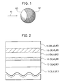
- a recording layer becomes as illustrated in Fig. 1, when a recording layer is molten by a laser beam spot.
- the molten region 60 corresponds to a region in which data is recorded
- the non-molten region 62 corresponds to a region in which data is not recorded yet.
- the molten region 60 becomes amorphous when cooled down, whereas the non-molten region 62 remains crystal. If a recording layer is not molten, the recording layer is not reduced amorphous.
- phase-change type optical recording medium which is capable of accurately carrying out simultaneous recording and verification, specifically carrying out verification by which it is confirmed whether data is properly recorded both in initial recording and over-recording.
- Another such object is to provide a phase-change type optical recording medium which is capable of carrying out verification with high accuracy in smaller period of time to thereby make it possible to record data with higher reliability.
- a phase-change type optical recording medium including (a) a substrate, (b) a recording layer formed on the substrate, a phase condition of the recording layer being changed when a laser beam is radiated thereonto, to thereby record, erase or reproduce data into or from the recording layer, and (c) a reflection layer formed on the recording layer for reflecting a laser beam having been radiated onto the recording layer, characterized in that the recording layer is formed so that the following equation (A) or (B) is established: Rc > Rm > Ra
- the recording layer By arranging the recording layer to have a thickness such that the above mentioned equation (A) is established, it is possible to have recording sensitivity suitable for recording data into and reproduce data from an optical recording medium, and accomplish simultaneous recording and verification.
- the phase-change type optical recording medium is capable of providing high reproducing output, being accessible at a higher speed, and recording data at a higher density.
- equation (B) includes reflectivity in the laser beam spot as one of standards for judgement, it is surely confirmed as to whether the recording layer has a molten or recorded region in the laser beam spot by means of the phase-change type optical recording medium meeting the equation (B). Thus, it is possible to carry out verification while data is being recorded into the phase-change type optical recording medium.
- the substrate and recording layer may be designed to have a thickness so that the equation (A) or (B) is established.
- the substrate and recording layer may be made of particular material so that the equation (A) or (B) is established.
- the phase-change type optical recording medium may further include a lower protection layer formed between the substrate and the recording layer, and an upper protection layer formed between the recording layer and the reflection layer, in which case the substrate, recording layer, lower protection layer and upper protection layer may be designed to have a thickness so that the equation (A) or (B) is established.
- the substrate, recording layer, lower protection layer and upper protection layer may be made of particular material so that the equation (A) or (B) is established.
- a laser beam may be radiated to the phase-change type optical recording medium in any directions. However, it is preferable that a laser beam is radiated through the substrate for the purpose of simplification of a driver optical system and reduction of a recording apparatus in size.
- the recording layer may be made of at least germanium (Ge), antimony (Sb) or tellurium (Te).
- the lower and upper protection layers may be made of any material suitable for optically recording medium. For instance, it is preferable that the lower and upper protection layers include ZnSSiO 2 , SiN, SiO, SiO 2 , TaO 2 or SiAlON.
- the reflecting layer may be made of any material suitable for optically recording medium. For instance, it is preferable that the reflecting layer includes Al, Ti, Ta, Cu, Au or Si as principal ingredient.
- the phase-change type optical recording medium may further include additional layers.
- the phase-change type optical recording medium may further include an UV resin protection layer formed on the reflection layer.
- the phase-change type optical recording medium may further include an intermediate layer between the UV resin protection layer and the reflection layer, which intermediate layer is made of the same material as that of the lower protection layer.
- the reflection layer is required to have a thickness through which a laser beam can pass. The provision of the intermediate layer enhances designability in the phase-change type optical recording medium.
- the optical recording medium may be constructed so that a difference between Rc and Ra necessary for reproducing data having been recorded in the medium is able to be obtained by a wavelength for reproducing data.
- crystal and amorphous regions formed in the recording layer have a phase difference, in order that a common wavelength can be employed for both recording and reproducing data.
- a phase difference ⁇ between crystal and amorphous regions both formed in the recording layer at a laser wavelength used for recording data meet the following equation (C). 30° ⁇
- the equation (C) may be established in various ways.
- the layers constituting the phase-change type optical recording medium may be designed to have a thickness or be made of particular material such that the equation (C) is established.
- the phase-change type optical recording medium may be fabricated by means of conventional processes such as sputtering.
- a method of optically recording data including the steps of (a) preparing a phase-change type optical recording medium, the phase-change type optical recording medium comprising: a substrate; a recording layer formed on the substrate, a phase condition of the recording layer being changed when a laser beam is radiated thereonto, to thereby record, erase or reproduce data into or from the recording layer; and a reflection layer formed on the recording layer for reflecting a laser beam having been radiated onto the recording layer, the recording layer being formed so that the following equation (A) or (B) is established: Rc > Rm > Ra
- the laser beam is radiated in pulse.
- Fig. 1 is a schematic view illustrating laser beam spot radiated while data is being recorded into an optical disc medium.
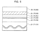
- Fig. 2 is a cross-sectional view of an optical disc medium in accordance with the first to fourth embodiments.
- Fig. 3 is a schematic view illustrating waveforms of laser beams radiated while data is being recorded into an optical disc medium.
- Fig. 4 is a graph showing relationship between recording laser power and carrier, noise and 2nd H/C levels in the first embodiment.
- Fig. 5 is a schematic view illustrating RF signal waveforms in the first embodiment.
- Fig. 6 is a cross-sectional view of an optical disc medium in the first to third reference example.
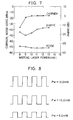
- Fig. 7 is a graph showing relationship between recording laser power and carrier, noise and 2nd H/C levels in the first reference example.
- Fig. 8 is a schematic view illustrating RF signal waveforms in the first reference example.
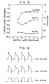
- Fig. 9 is a graph showing relationship between recording laser power and carrier, noise and 2nd H/C levels in the second embodiment.
- Fig. 10 is a schematic view illustrating RF signal waveforms in the second embodiment.
- Fig. 11 is a graph showing relationship between recording laser power and carrier, noise and 2nd H/C levels in the third embodiment.
- Fig. 12 is a schematic view illustrating RF signal waveforms obtained when data is being first recorded into the optical disc medium in accordance with the third embodiment.
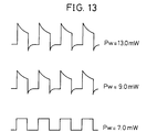
- Fig. 13 is a schematic view illustrating RF signal waveforms obtained when data is being over-recorded into the optical disc medium in accordance with the third embodiment.
- Fig. 14 is a block diagram of a circuit for judging whether data is properly recorded into an optical disc medium.
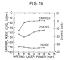
- Fig. 15 is a graph showing relationship between recording laser power and carrier, noise and 2nd H/C levels in the second reference example.
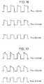
- Fig. 16 is a schematic view illustrating RF signal waveforms obtained when data is being first recorded into the optical disc medium in accordance with the second reference example.
- Fig. 17 is a schematic view illustrating RF signal waveforms obtained when data is being over-recorded into the optical disc medium in accordance with the second reference example.
- Fig. 18 is a graph showing relationship between recording laser power and carrier, noise and 2nd H/C levels in the fourth embodiment.
- Fig. 19 is a schematic view illustrating RF signal waveforms obtained when data is being first recorded into the optical disc medium in accordance with the fourth embodiment.
- Fig. 20 is a schematic view illustrating RF signal waveforms obtained when data is being over-recorded into the optical disc medium in accordance with the fourth embodiment.
- Fig. 21 is a graph showing relationship between recording laser power and carrier, noise and 2nd H/C levels in the third reference example.
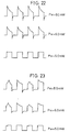
- Fig. 22 is a schematic view illustrating RF signal waveforms obtained when data is being first recorded into the optical disc medium in accordance with the third reference example.
- Fig. 23 is a schematic view illustrating RF signal waveforms obtained when data is being over-recorded into the optical disc medium in accordance with the third reference example.
- Fig. 2 illustrates a phase-change type optical disc medium in accordance with the first embodiment.
- the illustrated phase-change type optical disc medium has a transparent disc substrate 11 formed with a guide groove in a spiral form or guide grooves coaxially about a rotation axis of the disc substrate 11.
- a lower protection layer 12 made of ZnSSiO 2 and having a thickness of 160 nm
- a recording layer 13 made of GeSbTe and having a thickness of 15 nm
- an upper protection layer 14 made of ZnSSiO 2 and having a thickness of 25 nm
- a metal reflection layer 15 made of aluminum (Al) and having a thickness of 50 nm
- a UV resin protection layer 16 The layers 12 to 15 are deposited by sputtering.
- the lower protection layer 12, the recording layer 13 and the upper protection layer 14 are designed to have a thickness so that the equation (A) is established: Rc > Rm > Ra wherein Rc indicates a reflectivity to be obtained when the recording layer 13 is in crystal condition, Ra indicates a reflectivity to be obtained when the recording layer 13 is in amorphous condition, and Rm indicates a reflectivity to be obtained when the recording layer 13 is in mixed condition of molten condition and crystal or amorphous condition.
- a laser beam radiated through the disc substrate 11 passes through the lower protection layer 12, the recording layer 13 and the upper protection layer 14, and then is reflected at the metal reflection layer 15. Thus, the laser beam is directed in the reverse direction. A part of the radiated laser beam is reflected at the recording layer 13, and thus directed in the reverse direction.
- a reflectivity of the recording layer 13 can be controlled by designing the layers 12, 13 and 14 to have a certain thickness.
- the recording layer 13 was crystallized or initialized by radiating a laser beam at a linear velocity of 6 m/s and at erasion power of 6 mW to the optical disc medium, data was recorded into and reproduced from the phase-change type optical disc medium.
- Waveforms of laser beams used for recording data into the disc medium are illustrated in Fig. 3. The illustrated waveforms include reproduction power, erasion power, and recording power levels.
- Fig. 4 shows the dependency of C/N ratios of carrier, noise and 2nd H/C levels on recording laser power, obtained when data was recorded into the disc medium in the following conditions:
- Fig. 5 illustrates waveforms of RF signals obtained from the reflected laser beams while data is being recorded into the disc medium.
- Fig. 5 It is found in Fig. 5 that the waveforms are quite different between when the recording laser power is greater than 9.0 mW and when the recording laser power is smaller than 9.0 mW.
- the waveform found when the recording laser power is 13.0 mW indicates that data is properly recorded into the disc medium
- the waveform found when the recording laser power is 8.0 mW indicates that data is not properly recorded into the disc medium.
- the recording layer 13 is molten immediately after radiation of the recording laser power, and thus the reflectivity is reduced with the result of reduction in the reflected laser beam in the case of the recording laser power being 13.0 mW.
- the waveform changes into a unique shape as if undershoot occurs, because the reflectivity Rm of the recording laser beam spot including the molten region is smaller than the reflectivity Rc obtained when the recording layer is in non-recorded condition.
- the reflected laser beam is not reduced in an amount, because the recording layer 13 is not molten even if the recording laser power is increased up to the recording power level.
- Fig. 6 illustrates a phase-change type optical disc medium as a reference example.
- the illustrated phase-change type optical disc medium has a transparent disc substrate 21, and there are formed on the disc substrate 21 on this order a lower protection layer 22 made of ZnSSiO 2 and having a thickness of 100 nm, a recording layer 23 made of GeSbTe and having a thickness of 10 nm, an upper protection layer 24 made of ZnSSiO 2 and having a thickness of 20 nm, a metal reflection layer 25 made of aluminum (Al) and having a thickness of 60 nm, and a UV resin protection layer 26.
- the layers 22 to 25 are deposited by sputtering, similarly to the phase-change type optical disc medium in accordance with the first embodiment.
- the recording layer 23 was crystallized or initialized by radiating a laser beam at a linear velocity of 6 m/s and at erasion power of 6 mW to the optical disc medium, data was recorded into and reproduced from the phase-change type optical disc medium.
- Waveforms of laser beams used for recording data into the disc medium are the same as those illustrated in Fig. 3.
- Fig. 7 shows the dependency of C/N ratios on recording laser power, obtained when data was recorded into the disc medium in the following conditions:
- Fig. 8 illustrates waveforms of RF signals obtained from the reflected laser beams while data is being recorded into the disc medium.
- the layers 22 to 24 are designed to have a thickness so that the reflectivity Rc of a non-recorded or crystal region is almost equal to the reflectivity Ra of a recorded or amorphous region.
- C/N ratios can be obtained for carrier, noise and 2nd H/C levels.
- the reflected laser beam is not reduced in an amount because the recording layer 23 is not molten, even if the laser beam power is increased up to the recording power level.
- phase-change type optical disc medium in accordance with the second embodiment has the same layer structure as that of the optical disc medium in accordance with the first embodiment.
- the phase-change type optical disc medium in accordance with the second embodiment has a transparent disc substrate 31.
- a lower protection layer 32 made of ZnSSiO 2 and having a thickness of 170 nm
- a recording layer 33 made of GeSbTe and having a thickness of 15 nm
- an upper protection layer 34 made of ZnSSiO 2 and having a thickness of 15 nm
- a metal reflection layer 35 made of aluminum (Al) and having a thickness of 50 nm
- a UV resin protection layer 16 The layers 32 to 35 are deposited by sputtering.
- the lower protection layer 32, the recording layer 33 and the upper protection layer 34 are designed to have a thickness so that the equation (A) is established: Rc > Rm > Ra
- the recording layer 33 was crystallized or initialized by radiating a laser beam at a linear velocity of 6 m/s and at erasion power of 6 mW to the optical disc medium, data was recorded into and reproduced from the phase-change type optical disc medium.
- Waveforms of laser beams used for recording data into the disc medium are the same as those illustrated in Fig. 3.
- Fig. 9 shows the dependency of C/N ratios on recording laser power, obtained when data was recorded into the disc medium in the following conditions:
- Fig. 10 illustrates waveforms of RF signals obtained from the reflected laser beams while data is being recorded into the disc medium.
- the waveforms are quite different between when the recording laser power is greater than 10.0 mW and when the recording laser power is smaller than 10.0 mW.
- the waveform found when the recording power is 13.0 mW indicates that data is properly recorded into the disc medium, whereas the waveform found when the recording power is 9.0 mW indicates that data is not properly recorded into the disc medium.
- the recording layer 33 is molten immediately after radiation of the recording laser power, and thus the reflectivity is reduced with the result of reduction in the reflected laser beam in an amount in the case that the recording laser power is greater than 10.0 mW.
- the waveform changes into a unique shape as if undershoot occurs, because the reflectivity Rm of the recording laser beam spot including the molten region is smaller than the reflectivity Rc obtained when the recording layer 33 is in non-recorded condition.
- the reflected laser beam is not reduced in an amount, because the recording layer 33 is not molten even if the recording laser power is increased up to the recording power level.
- phase-change type optical disc medium in accordance with the third embodiment has the same layer structure as that of the optical disc medium in accordance with the first embodiment.
- the phase-change type optical disc medium in accordance with the third embodiment has a transparent disc substrate 41 made of polycarbonate and having a thickness of 1.2 mm.
- a lower protection layer 42 made of ZnSSiO 2 and having a thickness of 110 nm
- a recording layer 43 made of GeSbTe and having a thickness of 16 nm
- an upper protection layer 44 made of ZnSSiO 2 and having a thickness of 80 nm
- a metal reflection layer 45 made of aluminum (Al) and having a thickness of 50 nm
- a UV resin protection layer 16 The layers 42 to 45 are deposited by sputtering.
- a laser beam employed herein for recording data into the optical disc medium has a wavelength of 685 nm ⁇ 10 nm.
- a designed reflectivity in accordance with phase conditions of the recording layer 43 and a phase difference between crystal and amorphous regions in the recording layer 43 are as shown in Table 1 described later.
- the lower protection layer 42, the recording layer 43 and the upper protection layer 44 are designed to have a thickness so that the equation (B) is established:
- the recording layer 43 was crystallized or initialized by radiating a laser beam at a linear velocity of 6 m/s and at erasion power of 6 mW to the optical disc medium, data was recorded into and reproduced from the phase-change type optical disc medium.
- Waveforms of laser beams used for recording data into the disc medium are as illustrated in Fig. 3, similarly to the first and second embodiments.
- the waveforms include reproduction power, erasion power, and recording power levels.
- Fig. 11 shows the dependency of carrier, noise and 2nd H/C levels on recording laser power, obtained when data was recorded into the optical disc medium in the following conditions:
- Fig. 12 illustrates waveforms of RF signals obtained from the reflected laser beams while data is being first recorded into the disc medium.
- Fig. 13 illustrates waveforms of RF signals obtained from the reflected laser beams while data is being over-recorded into the disc medium.
- the waveforms of RF signals are quite different between when the recording laser power is greater than 9.0 mW and when the recording laser power is smaller than 8.0 mW.
- the waveform found when the recording laser power is 13.0 mW indicates that data is properly recorded into the disc medium
- the waveform found when the recording laser power is 7.0 mW indicates that data is not properly recorded into the disc medium.
- the recording layer 43 is molten immediately after radiation of the recording laser power, and thus the reflectivity is reduced with the result of reduction in the reflected laser beam in an amount in the case of the recording laser power being greater than 9.0 mW.
- the waveform changes into a unique shape as if undershoot occurs, because the reflectivity Rm of the recording laser beam spot including the molten region is smaller than the reflectivity Rc obtained when the recording layer 43 is in non-recorded condition.
- the reflected laser beam is not reduced in an amount, because the recording layer 43 is not molten, even if the recording laser power is increased up to the recording power level.
- Fig. 13 illustrating waveforms of RF signals in over-recording that the waveforms of RF signals are quite different between when the recording laser power is greater than 9.0 mW and when the recording laser power is smaller than 8.0 mW.
- the recording layer 43 is molten immediately after radiation of the recording laser power, and thus the reflectivity is reduced with the result of reduction in the reflected laser beam in an amount in the case that the recording laser power is greater than 9.0 mW.
- the waveform changes into a unique shape as if undershoot occurs, because the reflectivity Rm of the recording laser beam spot including the molten region is smaller than the reflectivity in the previous condition, namely, the reflectivity Ra for the recorded region or the reflectivity Rc for the non-recorded region.
- the reflected laser beam keeps unchanged in an amount, because the recording layer 43 is not molten, even if the recording laser power is increased up to the recording power level, and also because the reflectivity Rc of the crystal region is almost equal to the reflectivity Ra of the amorphous region.
- the waveforms (Fig. 13) of RF signals obtained in over-recording are almost identical with the waveforms (Fig. 12) of RF signals obtained when data is first recorded into the optical disc medium.
- Fig. 14 is a block diagram of a circuit for judging whether data is properly recorded into the optical disc medium.
- the illustrated circuit includes a peak hold circuit 51, an operational amplifier 52, an integration circuit 53 and a comparator 54. Synchronized signals are transmitted to the peak hold circuit 51, the integration circuit 53 and the comparator 54. In the illustrated circuit, an attention is paid to how reproduction outputs 55 or RF signals are varied immediately after rise-up of recording pulses.
- the reproduction outputs 55 are introduced into the operational amplifier 52 together with outputs from the peak hold circuit 51, and then an output from the operational amplifier 52 is integrated in the integration circuit 53.
- the integration is introduced into the comparator 54, and then compared to a reference voltage in the comparator 54.
- the comparator 54 transmits an output, because there can be obtained a waveform which would be generated when the recording laser power is greater than 9.0 mW, as illustrated in Figs. 12 and 13.
- verification can be accomplished while data is being recorded into an optical disc medium. If verification is accomplished based on variation of the reproduction output immediately after rise-up of recording pulses, it is possible to shorten a time necessary for verification, ensuring data recording with higher reliability and without reduction in data-recording speed.
- phase-change type optical disc medium as a reference example.
- the phase-change type optical disc medium as a reference example has the same structure except thicknesses of the substrate and layers.
- the phase-change type optical disc medium as a reference example has a transparent disc substrate 71 made of polycarbonate and having a thickness of 1.2 mm.
- a lower protection layer 72 made of ZnSSiO 2 and having a thickness of 160 nm
- a recording layer 73 made of GeSbTe and having a thickness of 14 nm
- an upper protection layer 74 made of ZnSSiO 2 and having a thickness of 20 nm
- a metal reflection layer 75 made of aluminum (Al) and having a thickness of 60 nm
- a UV resin protection layer 76 The layers 72 to 75 are deposited by sputtering.
- a laser beam employed herein for recording data into the optical disc medium has a wavelength of 685 nm ⁇ 10 nm.
- a designed reflectivity in accordance with phase conditions of the recording layer 73 and a phase difference between crystal and amorphous regions in the recording layer 73 are as shown in Table 1 described later.
- the recording layer 73 was crystallized or initialized by radiating a laser beam at a linear velocity of 6 m/s and at erasion power of 6 mW to the optical disc medium, data was recorded into and reproduced from the phase-change type optical disc medium.
- Waveforms of laser beams used for recording data into the disc medium are as illustrated in Fig. 3, similarly to the first to third embodiments.
- the waveforms include reproduction power, erasion power, and recording power levels.
- Fig. 15 shows the dependency of carrier, noise and 2nd H/C levels on recording laser power, obtained when data was recorded into the optical disc medium in the following conditions:
- Fig. 16 illustrates waveforms of RF signals obtained from the reflected laser beams while data is being first recorded into the optical disc medium
- Fig. 17 illustrates waveforms of RF signals obtained from the reflected laser beams while data is being over-recorded into the optical disc medium.
- C/N ratios can be obtained for carrier, noise and 2nd H/C levels by designing the layers 72 to 74 to have a thickness so that a difference between the reflectivity Rc of a non-recorded or crystal region and the reflectivity Ra of a recorded or amorphous region is large.
- the waveform of RF signals obtained when the recording laser power is greater than 10.0 mW is quite different from the waveform obtained when the recording laser power is smaller than 10.0 mW.
- the recording layer 73 is molten immediately after radiation of the recording laser power, and thus the reflectivity is reduced with the result of reduction in the reflected laser beam in an amount in the case that the recording laser power is greater than 10.0 mW where data is properly recorded into the optical disc medium.
- the waveform does not change into the unique shape like as if undershoot occurs, as found in the first to third embodiments, because the reflectivity Rm of the recording laser beam spot including the molten region is not so different from the reflectivity Rc obtained when the recording layer 73 is in non-recorded condition.
- the reflected laser beam is not reduced in an amount, because the recording layer 73 is not molten, even if the recording laser power is increased up to the recording power level.
- Fig. 17 illustrating waveforms of RF signals in over-recording that the reflected laser beam is changed in an amount in accordance with a difference prior to over-recording between the reflectivity Ra of a recorded region and the reflectivity Rc of a non-recorded region, because the recording layer 73 is not molten, even if the recording laser power is increased up to the recording power level.
- the reflectivity is reduced due to the recording layer being molten, resulting in that the reflected laser beam is reduced in an amount.
- the fluctuation is caused by a great difference prior to over-recording between the reflectivity Rc of a crystal region and the reflectivity Ra of an amorphous region.
- the fluctuation is of almost the same degree as the fluctuation in reflectivity caused by the melting of the recording layer.
- the waveform When the recording laser beam power is varied to the erasion power level, the waveform may be changed into the unique shape as if undershoot occurs, because the reflectivity Rm of a recording laser beam spot including a molten region may become larger or smaller than the reflectivity Ra for a recorded region or the reflectivity Rc for a non-recorded region.
- the fluctuation found immediately after rise-up of the recording pulses there is not found clear and characteristic reduction in RF signals as found in the third embodiment, even though the recording layer 73 commences to be molten, in which case it is impossible to precisely judge whether data is properly recorded into the optical disc medium or not.
- phase-change type optical disc medium in accordance with the fourth embodiment has the same layer structure as that of the optical disc medium in accordance with the first embodiment except thicknesses of the substrate and layers.
- the phase-change type optical disc medium in accordance with the fourth embodiment has a transparent disc substrate 81 made of polycarbonate and having a thickness of 0.6 mm.
- a lower protection layer 82 made of ZnSSiO 2 and having a thickness of 140 nm
- a recording layer 83 made of GeSbTe and having a thickness of 12 nm
- an upper protection layer 84 made of ZnSSiO 2 and having a thickness of 60 nm
- a metal reflection layer 85 made of aluminum (Al) and having a thickness of 60 nm
- a UV resin protection layer 86 The layers 82 to 85 are deposited by sputtering.
- a laser beam employed herein for recording data into the optical disc medium has a wavelength of 640 nm ⁇ 10 nm.
- a designed reflectivity in accordance with phase conditions of the recording layer 43 and a phase difference between crystal and amorphous regions in the recording layer 43 are as shown in Table 1 described later.
- the lower protection layer 82, the recording layer 83 and the upper protection layer 84 are designed to have a thickness so that the equation (B) is established:
- the recording layer 83 was crystallized or initialized by radiating a laser beam at a linear velocity of 6 m/s and at erasion power of 6 mW to the optical disc medium, data was recorded into and reproduced from the phase-change type optical disc medium.
- Waveforms of laser beams used for recording data into the disc medium are as illustrated in Fig. 3, similarly to the first and second embodiments.
- the waveforms include reproduction power, erasion power, and recording power levels.
- Fig. 18 shows the dependency of carrier, noise and 2nd H/C levels on recording laser power, obtained when data was recorded into the optical disc medium in the following conditions:
- Fig. 19 illustrates waveforms of RF signals obtained from the reflected laser beams while data is being first recorded into the disc medium.
- Fig. 20 illustrates waveforms of RF signals obtained from the reflected laser beams while data is being over-recorded into the disc medium.
- the layers 82 to 84 are designed to have a thickness so that the reflectivity Rc of a crystal or non-recorded region is almost equal to the reflectivity Ra of an amorphous or recorded region at a wavelength of a laser beam employed for recording and reproducing data, there can be obtained a preferred C/N ratio, since there is a phase difference between the crystal and amorphous regions.
- Fig. 19 It is found in Fig. 19 that the waveforms of RF signals are quite different between when the recording laser power is greater than 6.0 mW and when the recording laser power is smaller than 6.0 mW. Taking the waveforms illustrated in Fig. 19 into consideration together with Figs. 3 and 18, it is considered that data is properly recorded into the disc medium when the recording laser power is greater than 6.0 mW.
- the recording laser power is greater than 6.0 mW
- the recording layer 83 is molten immediately after radiation of the recording laser power, and thus the reflectivity is reduced with the result of reduction in the reflected laser beam in an amount.
- the waveform changes into a unique shape as if undershoot occurs, because the reflectivity Rm of the recording laser beam spot including the molten region is smaller than both the reflectivity Rc obtained when the recording layer 83 is in non-recorded condition and the reflectivity Ra obtained when the recording layer 83 is in recorded condition.
- the reflected laser beam is not reduced in an amount, because the recording layer 83 is not molten, even if the recording laser power is increased up to the recording power level.
- Fig. 20 illustrating waveforms of RF signals in over-recording that the waveforms of RF signals are quite different between when the recording laser power is greater than 6.0 mW and when the recording laser power is smaller than 6.0 mW.
- the recording layer 83 is molten immediately after radiation of the recording laser power, and thus the reflectivity is reduced with the result of reduction in the reflected laser beam in an amount in the case that the recording laser power is greater than 6.0 mW.
- the waveform changes into a unique shape as if undershoot occurs, because the reflectivity Rm of the recording laser beam spot including the molten region is smaller than the reflectivity in the previous condition, namely, the reflectivity Ra for the recorded region or the reflectivity Rc for the non-recorded region.
- the reflected laser beam keeps unchanged in an amount, because the recording layer 83 is not molten, even if the recording laser power is increased up to the recording power level, and also because the reflectivity Rc of the crystal region is almost equal to the reflectivity Ra of the amorphous region.
- phase-change type optical disc medium as a reference example in comparison with the phase-change type optical disc medium in accordance with the embodiment 4.
- the phase-change type optical disc medium as a reference example has the same structure except thicknesses of the substrate and layers.
- the phase-change type optical disc medium as a reference example has a transparent disc substrate 91 made of polycarbonate and having a thickness of 1.2 mm.
- a lower protection layer 92 made of ZnSSiO 2 and having a thickness of 110 nm
- a recording layer 93 made of GeSbTe and having a thickness of 14 nm
- an upper protection layer 94 made of ZnSSiO 2 and having a thickness of 30 nm
- a metal reflection layer 95 made of aluminum (Al) and having a thickness of 60 nm
- a UV resin protection layer 96 The layers 92 to 95 are deposited by sputtering.
- a laser beam employed herein for recording data into the optical disc medium has a wavelength of 640 nm ⁇ 10 nm.
- a designed reflectivity in accordance with phase conditions of the recording layer 93 and a phase difference between crystal and amorphous regions in the recording layer 93 are as shown in Table 1 described later.
- the recording layer 73 was crystallized or initialized by radiating a laser beam at a linear velocity of 6 m/s and at erasion power of 6 mW to the optical disc medium, data was recorded into and reproduced from the phase-change type optical disc medium.
- Waveforms of laser beams used for recording data into the disc medium are as illustrated in Fig. 3, similarly to the first to fourth embodiments.
- the waveforms include reproduction power, erasion power, and recording power levels.
- Fig. 21 shows the dependency of carrier, noise and 2nd H/C levels on recording laser power, obtained when data was recorded into the optical disc medium in the following conditions:
- Fig. 22 illustrates waveforms of RF signals obtained from the reflected laser beams while data is being first recorded into the optical disc medium
- Fig. 23 illustrates waveforms of RF signals obtained from the reflected laser beams while data is being over-recorded into the optical disc medium.
- C/N ratios can be obtained for carrier, noise and 2nd H/C levels by designing the layers 92 to 95 to have a thickness so that a difference between the reflectivity Rc of a non-recorded or crystal region and the reflectivity Ra of a recorded or amorphous region is large.
- the waveform does not change into the unique shape like as if undershoot occurs, as found in the first to fourth embodiments, because the reflectivity Rm of the recording laser beam spot including the molten region is almost identical to the reflectivity Rc obtained when the recording layer 93 is in non-recorded condition.
- the reflected laser beam is not reduced in an amount, because the recording layer 93 is not molten, even if the recording laser power is increased up to the recording power level.
- Fig. 23 illustrating waveforms of RF signals in over-recording that the recording layer 93 is not molten, even if the recording laser beam power is increased up to the recording power level, in the case that the recording laser power is smaller than 6.0 mW, and hence, the reflected laser beam is slightly changed in an amount in accordance with a difference prior to over-recording between the reflectivity Ra of the recorded region and the reflectivity Rc of the non-recorded region.
- the reflectivity is reduced due to the recording layer being molten, resulting in that the reflected laser beam is reduced in an amount.
- the fluctuation is caused by a great difference prior to over-recording between the reflectivity Rc of a crystal region and the reflectivity Ra of an amorphous region.
- the fluctuation is of almost the same degree as the fluctuation in reflectivity caused by the melting of the recording layer.
- the waveform When the recording laser beam power is varied to the erasion power level, the waveform may be changed into the unique shape as if undershoot occurs, because the reflectivity Rm of a recording laser beam spot including a molten region may become larger or smaller than the reflectivity Ra for a recorded region or the reflectivity Rc for a non-recorded region.
- the reflectivity Rm of a recording laser beam spot including a molten region may become larger or smaller than the reflectivity Ra for a recorded region or the reflectivity Rc for a non-recorded region.
- a phase-change type optical recording medium including a substrate, a recording layer, phase condition thereof being changed when a laser beam is radiated thereonto, to thereby record, erase or reproduce data into or from the recording layer, and a reflection layer, characterized in that the recording layer is formed so that the equation Rc > Rm > Ra is established wherein Rc indicates a reflectivity of the recording layer in crystal condition, Ra indicates a reflectivity of the recording layer in amorphous condition, and Rm indicates a reflectivity of the recording layer in molten and crystal or amorphous conditions.
- the substrate, recording layer and reflection layer may be designed to have a thickness and/or made of particular material so that the equation is established.
- the optical recording medium makes it possible to accurately accomplish verification by which it is confirmed whether data is properly recorded into the medium.
Landscapes
- Chemical & Material Sciences (AREA)
- Inorganic Chemistry (AREA)
- Optical Record Carriers And Manufacture Thereof (AREA)
- Optical Recording Or Reproduction (AREA)
Applications Claiming Priority (6)
| Application Number | Priority Date | Filing Date | Title |
|---|---|---|---|
| JP24294996 | 1996-09-13 | ||
| JP242949/96 | 1996-09-13 | ||
| JP24294996A JP3220020B2 (ja) | 1996-09-13 | 1996-09-13 | 相変化型光ディスク媒体と情報の記録・再生方法 |
| JP25462096 | 1996-09-26 | ||
| JP254620/96 | 1996-09-26 | ||
| JP8254620A JPH10106024A (ja) | 1996-09-26 | 1996-09-26 | 相変化型光記録媒体及びそれを用いた光記録方法 |
Publications (3)
| Publication Number | Publication Date |
|---|---|
| EP0829867A2 true EP0829867A2 (fr) | 1998-03-18 |
| EP0829867A3 EP0829867A3 (fr) | 1998-11-04 |
| EP0829867B1 EP0829867B1 (fr) | 2001-03-21 |
Family
ID=26536004
Family Applications (1)
| Application Number | Title | Priority Date | Filing Date |
|---|---|---|---|
| EP97306943A Expired - Lifetime EP0829867B1 (fr) | 1996-09-13 | 1997-09-08 | Support d'enregistrement optique de type à changement de phase et procédé d'enregistrement optique d'un tel support |
Country Status (3)
| Country | Link |
|---|---|
| US (1) | US6252844B1 (fr) |
| EP (1) | EP0829867B1 (fr) |
| KR (1) | KR100298972B1 (fr) |
Families Citing this family (2)
| Publication number | Priority date | Publication date | Assignee | Title |
|---|---|---|---|---|
| JP3698905B2 (ja) * | 1999-01-11 | 2005-09-21 | 日本電気株式会社 | 光学的情報記録媒体、その情報記録方法、その情報消去方法 |
| JP3679107B2 (ja) * | 2003-11-05 | 2005-08-03 | 株式会社リコー | 2層相変化型情報記録媒体とその記録方法 |
Family Cites Families (14)
| Publication number | Priority date | Publication date | Assignee | Title |
|---|---|---|---|---|
| JPS5922241A (ja) * | 1982-07-28 | 1984-02-04 | Fujitsu Ltd | 光デイスクの記録検査方式 |
| JPS60145537A (ja) | 1984-01-10 | 1985-08-01 | Nec Corp | 光学式情報記録方式及びその装置 |
| JPH074217B2 (ja) | 1986-08-20 | 1995-01-25 | 株式会社アドバンス | 電気細胞融合用電源 |
| JP2571776B2 (ja) | 1987-01-26 | 1997-01-16 | 株式会社日立製作所 | 情報の記録および消去方法 |
| KR950003182B1 (ko) * | 1990-03-14 | 1995-04-01 | 마쯔시다덴기산교 가부시기 가이사 | 광디스크 및 광학정보의 기록방법 |
| US5346740A (en) * | 1990-09-25 | 1994-09-13 | Matsushita Electric Industrial Co., Ltd. | Optical information recording medium |
| EP0566107B1 (fr) * | 1992-04-17 | 1998-03-18 | Matsushita Electric Industrial Co., Ltd. | Milieu d'enregistrement d'information optique et procédé de conception de sa structure |
| JP2897532B2 (ja) * | 1992-06-02 | 1999-05-31 | 日本電気株式会社 | 相変化型光ディスクの再生方法 |
| JP2806274B2 (ja) * | 1994-10-19 | 1998-09-30 | 日本電気株式会社 | 光学情報記録媒体 |
| JP2783179B2 (ja) * | 1995-02-27 | 1998-08-06 | 日本電気株式会社 | 光学情報の記録・再生方法及び記録・再生装置 |
| DE19612823C2 (de) * | 1995-03-31 | 2001-03-01 | Mitsubishi Chem Corp | Optisches Aufzeichnungsverfahren |
| US5798993A (en) * | 1995-05-29 | 1998-08-25 | Nec Corporation | System and method for simultaneously verifying optical data writing and optical data writing medium for use therein |
| JPH0973660A (ja) | 1995-09-06 | 1997-03-18 | Nec Corp | 光学的情報記録媒体ならびに記録中ベリファイ方法 |
| JP2836539B2 (ja) * | 1995-09-06 | 1998-12-14 | 日本電気株式会社 | 記録中ベリファイ装置 |
-
1997
- 1997-09-08 EP EP97306943A patent/EP0829867B1/fr not_active Expired - Lifetime
- 1997-09-08 US US08/925,534 patent/US6252844B1/en not_active Expired - Lifetime
- 1997-09-12 KR KR1019970047751A patent/KR100298972B1/ko not_active Expired - Fee Related
Also Published As
| Publication number | Publication date |
|---|---|
| EP0829867A3 (fr) | 1998-11-04 |
| KR100298972B1 (ko) | 2001-10-27 |
| EP0829867B1 (fr) | 2001-03-21 |
| KR19980024772A (ko) | 1998-07-06 |
| US6252844B1 (en) | 2001-06-26 |
Similar Documents
| Publication | Publication Date | Title |
|---|---|---|
| EP0233984B1 (fr) | Procédé pour enregistrer et reproduire des informations digitales et appareil à cet effet | |
| US6636477B1 (en) | Information recording medium and information recording device | |
| EP0784316B1 (fr) | Supports d'enregistrement optiques et unités d'enregistrement et de reproduction d'information | |
| US5646924A (en) | Recording and simultaneous verifying method of phase-changing type of information recording medium | |
| US5107482A (en) | Optical information recording method and apparatus and recording medium used therefor | |
| EP0957477A2 (fr) | Support d'enregistrement optique, procédé et système d'enregistrement et de reproduction d' information associés | |
| US6426936B1 (en) | Phase-change medium usable in phase-difference tracking | |
| EP0683485B1 (fr) | Disque optique à changement de phase | |
| JP2783179B2 (ja) | 光学情報の記録・再生方法及び記録・再生装置 | |
| US6333913B1 (en) | Optical recording medium and optical recording method | |
| EP0642123B1 (fr) | Support d'enregistrement d'information | |
| US5304440A (en) | Optical disk | |
| EP0260920A2 (fr) | Feuilles d'enregistrement optique amorphes du type "film mince" | |
| EP0594277B1 (fr) | Milieu d'enregistrement optique | |
| JP2001243655A (ja) | 光学的情報記録媒体とその製造方法、記録再生方法及び記録再生装置 | |
| US6768707B1 (en) | Phase-change type optical recording medium and method of optically recording with the same | |
| US6252844B1 (en) | Phase-change type optical recording medium and method of optically recording with the same | |
| JPH11134720A (ja) | 光学的情報記録媒体及びその記録再生方法 | |
| EP1513139B1 (fr) | Méthode pour déterminer le changement de la transmittance optique d'un support d'enregistrement optique | |
| EP0677840B1 (fr) | Procédé pour initialiser un disque optique | |
| US4806952A (en) | Information recording apparatus for recording/reproducing information by irradiating an information recording medium with an energy beam | |
| US6165579A (en) | Optical information recording medium and recording/reproduction method | |
| JP3277733B2 (ja) | 光ディスクへの光学的情報の記録方法および記録装置 | |
| Bernardus AJ Jacobs et al. | Improved high-density phase-change recording | |
| US5215862A (en) | Recording medium for information |
Legal Events
| Date | Code | Title | Description |
|---|---|---|---|
| PUAI | Public reference made under article 153(3) epc to a published international application that has entered the european phase |
Free format text: ORIGINAL CODE: 0009012 |
|
| AK | Designated contracting states |
Kind code of ref document: A2 Designated state(s): GB NL |
|
| PUAL | Search report despatched |
Free format text: ORIGINAL CODE: 0009013 |
|
| AK | Designated contracting states |
Kind code of ref document: A3 Designated state(s): AT BE CH DE DK ES FI FR GB GR IE IT LI LU MC NL PT SE |
|
| 17P | Request for examination filed |
Effective date: 19981005 |
|
| 17Q | First examination report despatched |
Effective date: 19981222 |
|
| AKX | Designation fees paid |
Free format text: GB NL |
|
| REG | Reference to a national code |
Ref country code: DE Ref legal event code: 8566 |
|
| GRAG | Despatch of communication of intention to grant |
Free format text: ORIGINAL CODE: EPIDOS AGRA |
|
| GRAG | Despatch of communication of intention to grant |
Free format text: ORIGINAL CODE: EPIDOS AGRA |
|
| GRAH | Despatch of communication of intention to grant a patent |
Free format text: ORIGINAL CODE: EPIDOS IGRA |
|
| GRAH | Despatch of communication of intention to grant a patent |
Free format text: ORIGINAL CODE: EPIDOS IGRA |
|
| GRAA | (expected) grant |
Free format text: ORIGINAL CODE: 0009210 |
|
| AK | Designated contracting states |
Kind code of ref document: B1 Designated state(s): GB NL |
|
| EN | Fr: translation not filed | ||
| REG | Reference to a national code |
Ref country code: GB Ref legal event code: IF02 |
|
| PLBE | No opposition filed within time limit |
Free format text: ORIGINAL CODE: 0009261 |
|
| STAA | Information on the status of an ep patent application or granted ep patent |
Free format text: STATUS: NO OPPOSITION FILED WITHIN TIME LIMIT |
|
| 26N | No opposition filed | ||
| PGFP | Annual fee paid to national office [announced via postgrant information from national office to epo] |
Ref country code: NL Payment date: 20040905 Year of fee payment: 8 |
|
| PG25 | Lapsed in a contracting state [announced via postgrant information from national office to epo] |
Ref country code: NL Free format text: LAPSE BECAUSE OF NON-PAYMENT OF DUE FEES Effective date: 20060401 |
|
| NLV4 | Nl: lapsed or anulled due to non-payment of the annual fee |
Effective date: 20060401 |
|
| PGFP | Annual fee paid to national office [announced via postgrant information from national office to epo] |
Ref country code: GB Payment date: 20090902 Year of fee payment: 13 |
|
| GBPC | Gb: european patent ceased through non-payment of renewal fee |
Effective date: 20100908 |
|
| PG25 | Lapsed in a contracting state [announced via postgrant information from national office to epo] |
Ref country code: GB Free format text: LAPSE BECAUSE OF NON-PAYMENT OF DUE FEES Effective date: 20100908 |