EP0830251B1 - Zweiseitiger farbdruckapparat und zugehörige umkehrbare druckkopfhaltevorrichtung - Google Patents
Zweiseitiger farbdruckapparat und zugehörige umkehrbare druckkopfhaltevorrichtung Download PDFInfo
- Publication number
- EP0830251B1 EP0830251B1 EP96920200A EP96920200A EP0830251B1 EP 0830251 B1 EP0830251 B1 EP 0830251B1 EP 96920200 A EP96920200 A EP 96920200A EP 96920200 A EP96920200 A EP 96920200A EP 0830251 B1 EP0830251 B1 EP 0830251B1
- Authority
- EP
- European Patent Office
- Prior art keywords
- printing
- strip
- assemblies
- print head
- applying
- Prior art date
- Legal status (The legal status is an assumption and is not a legal conclusion. Google has not performed a legal analysis and makes no representation as to the accuracy of the status listed.)
- Expired - Lifetime
Links
- 238000007639 printing Methods 0.000 title claims abstract description 103
- 230000002441 reversible effect Effects 0.000 title claims abstract description 11
- 230000000712 assembly Effects 0.000 claims abstract description 42
- 238000000429 assembly Methods 0.000 claims abstract description 42
- 238000007651 thermal printing Methods 0.000 claims abstract description 12
- 238000000576 coating method Methods 0.000 description 2
- 238000000034 method Methods 0.000 description 2
- ORQBXQOJMQIAOY-UHFFFAOYSA-N nobelium Chemical compound [No] ORQBXQOJMQIAOY-UHFFFAOYSA-N 0.000 description 2
- 206010057040 Temperature intolerance Diseases 0.000 description 1
- 239000003086 colorant Substances 0.000 description 1
- 230000008543 heat sensitivity Effects 0.000 description 1
- 230000007246 mechanism Effects 0.000 description 1
- 238000007645 offset printing Methods 0.000 description 1
- 229920006267 polyester film Polymers 0.000 description 1
- 230000008261 resistance mechanism Effects 0.000 description 1
- 238000004513 sizing Methods 0.000 description 1
- 239000000758 substrate Substances 0.000 description 1
Images


Classifications
-
- B—PERFORMING OPERATIONS; TRANSPORTING
- B41—PRINTING; LINING MACHINES; TYPEWRITERS; STAMPS
- B41J—TYPEWRITERS; SELECTIVE PRINTING MECHANISMS, i.e. MECHANISMS PRINTING OTHERWISE THAN FROM A FORME; CORRECTION OF TYPOGRAPHICAL ERRORS
- B41J3/00—Typewriters or selective printing or marking mechanisms characterised by the purpose for which they are constructed
- B41J3/54—Typewriters or selective printing or marking mechanisms characterised by the purpose for which they are constructed with two or more sets of type or printing elements
-
- B—PERFORMING OPERATIONS; TRANSPORTING
- B41—PRINTING; LINING MACHINES; TYPEWRITERS; STAMPS
- B41J—TYPEWRITERS; SELECTIVE PRINTING MECHANISMS, i.e. MECHANISMS PRINTING OTHERWISE THAN FROM A FORME; CORRECTION OF TYPOGRAPHICAL ERRORS
- B41J2/00—Typewriters or selective printing mechanisms characterised by the printing or marking process for which they are designed
- B41J2/315—Typewriters or selective printing mechanisms characterised by the printing or marking process for which they are designed characterised by selective application of heat to a heat sensitive printing or impression-transfer material
- B41J2/32—Typewriters or selective printing mechanisms characterised by the printing or marking process for which they are designed characterised by selective application of heat to a heat sensitive printing or impression-transfer material using thermal heads
- B41J2/325—Typewriters or selective printing mechanisms characterised by the printing or marking process for which they are designed characterised by selective application of heat to a heat sensitive printing or impression-transfer material using thermal heads by selective transfer of ink from ink carrier, e.g. from ink ribbon or sheet
Definitions
- the instant invention relates to apparatus for printing on two sides of a continuous strip, and more particularly to a two-sided printing apparatus which is capable of printing in multiple colors on two sides of a continuous strip.
- the U.S. Patent to Gaskill et al No. 4,811,036 represents the closest prior art to the subject invention of which the applicant is aware.
- the Gaskill patent discloses a printing apparatus operative for applying images to opposite sides of a continuous strip at first and second sequential printing stations.
- the first printing station is operative for applying a single color image (usually black) to the lower side of the strip
- the second printing station is operative for applying a single color image to the upper side of the strip.
- the apparatus further includes a feed assembly driven by a stepping motor for advancing the continuous strip from the first printing station to the second printing station and a controller responsive to a predetermined number of stepped rotational increments of the stepping motor for coordinating the printing operations at the first and second printing stations. While the above-described apparatus is effective for applying single color images to each of the opposite surfaces of the strip, the apparatus is not capable of printing multiple-color images on either side of the strip.
- US Patent 4,857,941 describes a recording device for thermal color recording of a medium having two color coupler layers on one side and another color coupler layer on the other side of a transparent support.
- the layer on the side with two layers and having the higher heat sensitivity is first thermally imaged and then optically fixed. Thereafter, the remaining layer on that side and the layer on the other side are thermally imaged.
- a thermal printing apparatus for applying images to opposite first and second sides of a continuous strip comprising:
- the provision of printing apparatus for applying a multiple-color image to one side of a continuous strip while also applying a single or multiple color image to a second side of the strip; and the provision of printing apparatus having multiple reversible print heads for printing on either of two opposite sides of a continuous strip.
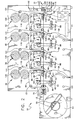
- the printing apparatus of the instant invention is illustrated and generally indicated at 10 in Figs. 1-5.
- the instant thermal printing apparatus 10 is operable for printing multiple thermal images onto the opposite first and second sides of a continuous strip of print media 12.
- the apparatus 10 includes a back plate generally indicated at 14, first, second, third and fourth printing assemblies generally indicated at 16, 18, 20, and 22 respectively, operable at first, second, third, and fourth printing stations 24, 26, 28, and 30 respectively for printing first, second, third and fourth images onto the strip 12, and a feed assembly generally indicated at 32 for drawing the strip 12 through the printing stations.
- the apparatus 10 further includes a stepping motor 34 (broken lines Fig. 2), first, second, third and fourth printing film drive assemblies generally indicated at 36, 38, 40 and 42 respectively, and a controller 44 (broken lines (Fig. 2).
- the printing film drive assemblies 36, 38, 40, 42 are operated to supply first, second, third and fourth printing films 46, 48, 50, 52 respectively, to the printing stations 24, 26, 28, 30, and the stepping motor 34 is operated to advance the strip 12 in a substantially taught disposition between the printing stations.
- the controller 44 is responsive to a predetermined number of stepped rotational increments of the stepping motor 34 for controlling the printing assemblies 16, 18, 20, 22 to apply images to the opposite sides of the strip 12 so that the longitudinal positions of the images are precisely coordinated throughout the longitudinal extent of the strip 12.
- the strip 12 preferably comprises a continuous strip of a paper or non-woven substrate having a width of between 2.5 and 10.2 cm (1 and 4 inches).
- the strip 12 is preferably provided in a continuous roll 54 which is mounted on brackets 56 mounted to the back plate 14.
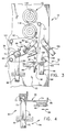
- Printing assembly 22 comprises a platen assembly generally indicated at 58, a thermal print head 60, and a thermal print head mounting assembly 62.
- the platen assembly comprises a cylindrical platen 64 having a rubberized outer shell, and a platen mounting bracket 66 which is operative for rotatably receiving the platen 64 in parallel relation to the print head.
- the mounting bracket 66 is mounted to the back plate as illustrated in Figs. 1-3.
- the print head 60 preferably comprises a conventional thermal print head having an array of discretely energizable thermal elements. Energizing of the thermal elements is controlled by the controller 44 through conventional cable means (not shown).
- the print head mounting assembly 62 is operative for mounting the print head 60 in substantially parallel relation to the platen 64 so that it is movable between an actuated position (Fig. 2) wherein the print head 60 is positioned in biased engagement with the platen 64, and an unactuated position (Fig. 3) wherein the print head 60 is lifted out of engagement with the platen 64.
- the print head mounting assembly 62 (see Fig. 4) comprises a mounting bar generally indicated at 68, and a pivot bar 70.
- the mounting bar 68 includes a C-shaped channel portion 72 which is slidably received over the pivot bar 70, and an arm portion 74 which extends outwardly from the channel portion 72 and receives the print head 60 at the terminal end thereof.
- a cap 76 is received at the end of the pivot bar 70 for maintaining the mounting bar 68 on the pivot bar 70.
- the mounting bar 68 is thus pivotably movable about the pivot bar 70 for moving the print head 60 into and out of engagement with the platen 64.
- the print head mounting assembly 62 further comprises a pivotable toggle element generally indicated at 80 for maintaining the print head 60 in biased engagement with the platen 64.
- the toggle element 80 is pivotably mounted to the back plate 14 on a pin 82 at one end thereof while the opposite end is pivotably movable into engagement with the terminal end of the arm portion 74 of the mounting bar 68. Movement of the toggle element is guided by pin 83.
- the toggle element 80 further includes a spring element 84 (broken lines) which actually engages the upper surface of the mounting bar 68.
- the spring element 84 urges the print head mounting assembly 62 downwardly into biased engagement with the platen 64.
- the terminal end of the mounting bar includes a flange 86 for limiting forward movement of the toggle element 80.
- a means is provided for adjusting the longitudinal position of the print head 60 with respect to the platen 64.
- the pivot bar 70 has a cam shape as illustrated in Fig. 4. Attached to the end of the pivot bar 70 adjacent to the back plate 14 is an actuator bar 88.
- the terminal end of the actuator bar 88 includes an arcuate slot 90 which is received over a guide pin 92 for guiding pivot movement of the actuator bar 88.
- pivoting movement (arrow 94) of the actuator bar 88 rotates the cam-shaped pivot bar 70 causing the mounting bar 68 to move forward or backward (arrow 96).
- the first second, and third printing assemblies 16, 18, 20, respectively are identical to the first printing assembly 22 described hereinabove, and hence will not be described separately. As illustrated in Figs. 1 and 2, the first, second third and fourth printing assemblies 16, 18, 20, 22 are mounted to the back plate 14 so that they are operative for applying four separate images to the first or upper side of the strip 12. However, as will be described hereinafter, the first and third printing assemblies 16 and 20 can be reversibly mounted so that either or both are operative for applying images to the second or underside of the strip 12 while the second and fourth printing assemblies 18, 22 are still operative for applying images to the upper side of the strip 12.
- the feed assembly 32 is operative for advancing the strip 12 through the apparatus 10 so that it passes through the first, second, third and fourth printing stations 24, 26, 28, 30. More specifically, the feed assembly 32 comprises a drive assembly 98, a pressure roller 100, and a toggle element 102 for urging the pressure roller 100 into pressured engagement with the drive roller assembly 98.
- the drive assembly 98 comprises a drive roller 104 having a rubberized outer shell, and a mounting bracket 106 for mounting the drive roller 104 to the back plate 14.
- the pressure roller 100 includes a rubberized outer shell, and it is rotatably mounted in a bracket 108 which is pivotably mounted to the back plate 14 on a pivot pin 110.
- the toggle element 102 is substantially identical to the previously described toggle elements 80 and it is pivotably movable for urging the pressure roller 100 into biased engagement with the drive roller 104 so that when the drive roller 104 is rotated, the rollers 100, 104 cooperate for advancing the strip 12 through the apparatus 10.
- the stepping motor 34 (Fig. 2) is drivingly coupled to the drive roller 104 via a drive belt 112 and pulley 114, 116 attached to the stepping motor 34 and drive roller 104.
- the stepping motor 34 is operative at a uniform rate of stepped rotational increments per revolution in order to insure precise longitudinal orientation of the different images applied to opposite sides of the strip 12 at the printing stations 24, 26, 28, 30.
- the first, second, third and fourth printing film drive assemblies 36, 38, 40, 42 are operative for advancing their respective printing films 46, 48, 50, 52 through the respective printing stations 24, 26, 28, 30, so that the printing films pass between the respective print head 60 and the strip 12.
- the printing films 46, 48, 50, 52 comprise conventional thin polyester films having heat sensitive coatings thereon, and they are responsive to heat from the thermal print heads 60 for transferring selected portions of the coatings thereon onto the strip 12 to apply images to the strip 12.
- the printing films each preferably have a width of about 1 to 4 inches.
- the film drive assemblies 36, 38, 40, 42 each comprise a film supply hub 118 containing a supply of film, and a film take-up hub 120 and several guide rolls 121 for guiding the films into proper alignment into the printing station.
- the supply hubs 118 are rotatably mounted to the back plate 14 and include a resistance mechanism (not shown) for applying a slight resistance to rotation of the hub 118 in order to maintain the films in a substantially taught condition as they are passed through the respective print station.
- the take-up hubs 120 are also rotatably mounted to the back plate 14 and they are drivingly coupled to drive motors (not shown) through conventional slip clutch mechanisms (not shown). During operation of the apparatus 10, the drive motors are operated to rotate the take-up hubs 120 in order to advance the films through the printing stations.
- the slip clutches are designed so that they increasingly slip as the wound diameters of the take-up hubs 120 are increased in order to maintain substantially constant film speeds throughout the printing processes.
- the controller 44 is operable in a conventional manner and includes a programmable microprocessor which can be programmed for control of the stepping motor 34, thermal print heads 60, and the printing film drive assemblies 36, 38, 40, 42. More specifically, the controller 44 is programmed so that it is responsive to a predetermined number of stepped rotational increments of the stepping motor 34 for coordinating the energizations of the print heads 60 in the printing assemblies 16, 18, 20, 22.
- the controller 44 actuates the first printing assembly 16 to apply a first image to the strip 12 at the first printing station 24, and then for actuating the second printing assembly 18 for applying an image to the strip 12 at the second printing station 26 after a predetermined number of stepped rotational increments of the stepping motor 34 which corresponds to the distance between the two printing stations 24, 26.
- the controller further controls the third and fourth printing assemblies 20, 22 for similarly applying third and fourth images to the strip 12. In other words, the controller 44 sequentially coordinates the longitudinal positions of the images on the strip 12.
- the controller 44 is also operative for controlling the printing film drive assemblies 36, 38, 40, 42 so that the films 46, 48, 50, 52 are passed through the printing stations 24, 26, 28, 30 as the strip 12 is advanced.
- the first printing assembly 16 and printing film drive assemly 36 are illustrated in a reversed mounting position wherein the first printing assembly 16 is now operative for applying an image to the second or underside of the strip 12.
- the back plate 14 is provided with appropriate mounting apertures 122 for receiving the components of the print head mounting assembly 62, as well as the hubs 118, 120 and guide rollers 121 of the printing film drive assembly 36.
- Apertures 122A indicate the positions where the print head mounting components and printing film drive components are attached when mounted in the first position.
- the third printing station 28 is also provided with appropriate mounting apertures 124 for reverse mounting of the third printing assembly 20 and printing film drive assembly 40.
- the first and third printing assemblies 16, 20 are operative for applying images to either the upper or lower side of the strip 12. Accordingly, multi-color images can be applied to either or both sides of the strip 12.
- one of the printing assemblies (usually the first, i.e. 16) is reverse mounted for applying a black and white image to the lower side of the strip 12 while the remaining three printing assemblies 18, 20, 22 are mounted for applying several overlying color images to the upper side of the strip 12.
- Such an application is highly useful in the garment industry for printing clothing labels or tags having a color company logo on one side thereof while having black and white bar code, sizing and pricing information on the reverse side thereof.
- the apparatus 10 has further been found to be cost effective and efficeint for printing small batches of the labels or tags for specialty clothing outfits wherein the prior methods of printing such labels required offset printing in large numbers to achieve any kind of cost effectiveness.
- the instant invention provides a novel and effective apparatus 10 for applying multiple images to either or both upper and lower sides of a continuous strip of print media 12.
- the apparatus 10 includes four printing assemblies 16, 18, 20, 22 which are individually operable for applying an image to the surface of the strip 12. In one type of set-up, all four printing assemblies 16, 18, 20, 22 are mounted for applying images to a single side of the strip 12. However, the first and third printing assemblies 16, 20 are reversible so that either one or two images can be applied to the underside of the strip 12.
- the apparatus 10 thus allows for the printing of multiple images on the upper side of the strip 12, while simultaneously allowing the printing of an image onto the underside of the strip 12.
- the multiple image printing of the apparatus 10 combined with the reversibility of two of the printing assemblies 16, 20 makes it highly effective for printing labels and tags for the garment industry, as well as other applications in the retail industry. For these reasons, the instant invention is believed to represent a significant advancement in the art which has substantial commercial merit.
Landscapes
- Printers Characterized By Their Purpose (AREA)
- Electronic Switches (AREA)
- Common Mechanisms (AREA)
Claims (2)
- Apparat (10) zum Aufbringen von Abbildungen auf gegenüberliegende erste und zweite Seiten eines durchgehenden Streifens (12) mit:wobei die Vorrichtungen (16, 18, 20, 22) jeweils eine drehbare Walze (58) und einen Thermodruckkopf (60) umfassen, der gegen seine jeweilige Walze (58) gespannt ist, wobei der durchgehende Streifen (12) zwischen den Thermodruckköpfen (60) und den Walzen (58) hindurchläuft, und wobei die Vorrichtungen ferner eine Thermodruckfolie (46, 48, 50, 52) umfassen, die zwischen dem durchgehenden Streifen (12) und den Thermodruckköpfen (60) hindurchläuft; und mitmehreren Druckvorrichtungen (16, 18, 20, 22) zum Aufbringen von Abbildungen auf eine erste Seite eines durchgehenden Streifens (12) von Druckmedien,dadurch gekennzeichnet, daß mindestens eine der Druckvorrichtungen (16, 18, 20, 22) eine umstellbare Montagevorrichtung (62) aufweist, die derart angeordnet werden kann, daß Abbildungen auf die gegenüberliegende Seite des durchgehenden Streifens (12) aufgebracht werden.einer Antriebsvorrichtung (98) zum Vorwärtsbewegen des durchgehenden Streifens (12) in Längsrichtung,
- Apparat nach Anspruch 1,
bei dem jeder Druckkopf zwischen einer Druckposition, in der der Druckkopf mit seiner jeweiligen Walze in Eingriff steht, und einer Ruhelage verschwenkbar ist, in der der Druckkopf von der Walze gelöst ist, und ferner mit einem Kniehebel-Element, um den Druckkopf in der Druckposition gegen die Walze zu spannen.
Applications Claiming Priority (3)
| Application Number | Priority Date | Filing Date | Title |
|---|---|---|---|
| US08/461,392 US5675369A (en) | 1995-06-05 | 1995-06-05 | Two-sided color printing apparatus and reversible print head mounting assembly therefor |
| US461392 | 1995-06-05 | ||
| PCT/US1996/006799 WO1996039300A1 (en) | 1995-06-05 | 1996-05-14 | Two-sided color printing apparatus and reversible print head mounting assembly therefor |
Publications (3)
| Publication Number | Publication Date |
|---|---|
| EP0830251A1 EP0830251A1 (de) | 1998-03-25 |
| EP0830251A4 EP0830251A4 (de) | 1999-07-21 |
| EP0830251B1 true EP0830251B1 (de) | 2002-03-13 |
Family
ID=23832377
Family Applications (1)
| Application Number | Title | Priority Date | Filing Date |
|---|---|---|---|
| EP96920200A Expired - Lifetime EP0830251B1 (de) | 1995-06-05 | 1996-05-14 | Zweiseitiger farbdruckapparat und zugehörige umkehrbare druckkopfhaltevorrichtung |
Country Status (6)
| Country | Link |
|---|---|
| US (1) | US5675369A (de) |
| EP (1) | EP0830251B1 (de) |
| AT (1) | ATE214334T1 (de) |
| CA (1) | CA2219446A1 (de) |
| DE (1) | DE69619811T2 (de) |
| WO (1) | WO1996039300A1 (de) |
Cited By (1)
| Publication number | Priority date | Publication date | Assignee | Title |
|---|---|---|---|---|
| CN107953680A (zh) * | 2017-11-21 | 2018-04-24 | 曲阜市玉樵夫科技有限公司 | 一种标识打印机及其打印方法 |
Families Citing this family (19)
| Publication number | Priority date | Publication date | Assignee | Title |
|---|---|---|---|---|
| US5973711A (en) * | 1997-11-14 | 1999-10-26 | Astro-Med, Inc. | Two-sided color printing apparatus |
| US6151037A (en) | 1998-01-08 | 2000-11-21 | Zebra Technologies Corporation | Printing apparatus |
| ES2157709B1 (es) * | 1998-01-09 | 2002-03-01 | Betaprint S L | Dispositivo impresor por transferencia termica. |
| US6432528B1 (en) * | 1998-12-09 | 2002-08-13 | 3M Innovative Properties Company | Variably printed tape and system for printing and applying tape onto surfaces |
| US6313861B2 (en) * | 1999-04-27 | 2001-11-06 | Astro-Med, Inc. | Thermal transfer printer with print film saving system and print media tensioning system |
| US6031555A (en) | 1999-04-27 | 2000-02-29 | Astro-Med, Inc. | Color printer having a printing film conserving mechanism |
| US6145436A (en) * | 1999-04-27 | 2000-11-14 | Astro-Med, Inc. | Label transport shuttle for a printing device |
| US6415842B1 (en) | 1999-06-11 | 2002-07-09 | 3M Innovative Properties Company | System for printing and applying tape onto surfaces |
| US6537406B1 (en) | 2000-04-03 | 2003-03-25 | 3M Innovative Properties Company | Vacuum-assisted tape applicator |
| US6652172B2 (en) | 2001-01-05 | 2003-11-25 | 3M Innovative Properties Company | Method and apparatus for handling linerless label tape within a printing device |
| US6894713B2 (en) * | 2002-02-08 | 2005-05-17 | Kodak Polychrome Graphics Llc | Method and apparatus for laser-induced thermal transfer printing |
| US7439995B2 (en) * | 2002-02-08 | 2008-10-21 | Kodak Polychrome Graphics, Gmbh | Method and apparatus for laser induced thermal transfer printing |
| US6884312B2 (en) * | 2002-04-12 | 2005-04-26 | 3M Innovative Properties Company | Apparatus for printing and applying tape and methods of printing and applying tape |
| DE10327742B3 (de) * | 2003-06-18 | 2004-08-12 | Espera-Werke Gmbh | Druckvorrichtung |
| US6910820B2 (en) | 2003-07-25 | 2005-06-28 | 3M Innovative Properties Company | Apparatus and method for handling linerless label tape |
| US7179002B2 (en) * | 2003-12-31 | 2007-02-20 | Samsung Electronics Co., Ltd. | Thermal image forming apparatus |
| WO2006055444A2 (en) * | 2004-11-16 | 2006-05-26 | Polaroid Corporation | Double sided thermal printing device with an improved image registration |
| ITPD20060112A1 (it) * | 2006-03-30 | 2007-09-30 | Hellermanntyton Srl | Apparato stampante per la stampa mono/bilaterale di un supporto continuo |
| WO2008116068A1 (en) * | 2007-03-20 | 2008-09-25 | Kellogg Company | Concurrently printing an image on a food product and a corresponding image on packaging for the food product |
Family Cites Families (5)
| Publication number | Priority date | Publication date | Assignee | Title |
|---|---|---|---|---|
| JPS5769071A (en) * | 1980-10-17 | 1982-04-27 | Fuji Xerox Co Ltd | Duplex recorder |
| JP2585586B2 (ja) * | 1987-04-16 | 1997-02-26 | 富士写真フイルム株式会社 | 多色感熱記録装置 |
| US4811036A (en) * | 1987-08-03 | 1989-03-07 | Astro-Med Inc. | Printing apparatus and print head mounting assembly therefor |
| JPH01182053A (ja) * | 1988-01-14 | 1989-07-19 | Brother Ind Ltd | 両面印字可能なプリンタ |
| US5486057A (en) * | 1992-05-06 | 1996-01-23 | Eltron International, Inc. | Multicolor printer system having multiple print heads |
-
1995
- 1995-06-05 US US08/461,392 patent/US5675369A/en not_active Expired - Lifetime
-
1996
- 1996-05-14 WO PCT/US1996/006799 patent/WO1996039300A1/en not_active Ceased
- 1996-05-14 CA CA002219446A patent/CA2219446A1/en not_active Abandoned
- 1996-05-14 AT AT96920200T patent/ATE214334T1/de not_active IP Right Cessation
- 1996-05-14 EP EP96920200A patent/EP0830251B1/de not_active Expired - Lifetime
- 1996-05-14 DE DE69619811T patent/DE69619811T2/de not_active Expired - Lifetime
Cited By (1)
| Publication number | Priority date | Publication date | Assignee | Title |
|---|---|---|---|---|
| CN107953680A (zh) * | 2017-11-21 | 2018-04-24 | 曲阜市玉樵夫科技有限公司 | 一种标识打印机及其打印方法 |
Also Published As
| Publication number | Publication date |
|---|---|
| US5675369A (en) | 1997-10-07 |
| EP0830251A4 (de) | 1999-07-21 |
| DE69619811D1 (de) | 2002-04-18 |
| EP0830251A1 (de) | 1998-03-25 |
| ATE214334T1 (de) | 2002-03-15 |
| WO1996039300A1 (en) | 1996-12-12 |
| CA2219446A1 (en) | 1996-12-12 |
| DE69619811T2 (de) | 2002-11-28 |
Similar Documents
| Publication | Publication Date | Title |
|---|---|---|
| EP0830251B1 (de) | Zweiseitiger farbdruckapparat und zugehörige umkehrbare druckkopfhaltevorrichtung | |
| EP0346412B1 (de) | Belastungsmechanismus für einen nachgiebigen druckkopf in thermodruckern | |
| US5971634A (en) | Method of printing | |
| US5806999A (en) | Double-side printing system | |
| US4750007A (en) | Ink sheet cassette and image recording apparatus using the same | |
| US5609425A (en) | Thermal sublimation printer for use with different ribbons | |
| US5611629A (en) | Multiple print head nonimpact printing apparatus | |
| KR960010417B1 (ko) | 감열전사 기록방법 및 장치와 그를 위한 잉크지카세트 | |
| US5973711A (en) | Two-sided color printing apparatus | |
| US6232995B1 (en) | Color printer having a printing film conserving mechanism | |
| US6313861B2 (en) | Thermal transfer printer with print film saving system and print media tensioning system | |
| EP0638432B1 (de) | Rotierende Klammervorrichtung | |
| US4811036A (en) | Printing apparatus and print head mounting assembly therefor | |
| JPH0342191B2 (de) | ||
| JPH085235B2 (ja) | 熱転写記録装置 | |
| US6380963B1 (en) | Carrier utilization in printing | |
| JP2604634B2 (ja) | 熱転写記録装置 | |
| JP2947078B2 (ja) | 熱転写印刷装置 | |
| JPH0768815A (ja) | プリント方法及び装置 | |
| JPH053838B2 (de) | ||
| JP3483404B2 (ja) | サーマルプリンタ | |
| JPH08300697A (ja) | 熱転写記録装置及びインクシート搬送装置 | |
| JP3172068B2 (ja) | 熱転写プリンタ | |
| JPH0634122Y2 (ja) | プリンタ装置 | |
| KR0168281B1 (ko) | 열전사 프린터 |
Legal Events
| Date | Code | Title | Description |
|---|---|---|---|
| PUAI | Public reference made under article 153(3) epc to a published international application that has entered the european phase |
Free format text: ORIGINAL CODE: 0009012 |
|
| 17P | Request for examination filed |
Effective date: 19971121 |
|
| AK | Designated contracting states |
Kind code of ref document: A1 Designated state(s): AT BE CH DE DK ES FI FR GB GR IE IT LI LU MC NL PT SE |
|
| A4 | Supplementary search report drawn up and despatched |
Effective date: 19990607 |
|
| AK | Designated contracting states |
Kind code of ref document: A4 Designated state(s): AT BE CH DE DK ES FI FR GB GR IE IT LI LU MC NL PT SE |
|
| RIC1 | Information provided on ipc code assigned before grant |
Free format text: 6B 41J 3/60 A, 6B 41J 25/34 B |
|
| 17Q | First examination report despatched |
Effective date: 20001103 |
|
| GRAG | Despatch of communication of intention to grant |
Free format text: ORIGINAL CODE: EPIDOS AGRA |
|
| EL | Fr: translation of claims filed | ||
| GRAG | Despatch of communication of intention to grant |
Free format text: ORIGINAL CODE: EPIDOS AGRA |
|
| GRAH | Despatch of communication of intention to grant a patent |
Free format text: ORIGINAL CODE: EPIDOS IGRA |
|
| GRAH | Despatch of communication of intention to grant a patent |
Free format text: ORIGINAL CODE: EPIDOS IGRA |
|
| REG | Reference to a national code |
Ref country code: GB Ref legal event code: IF02 |
|
| GRAA | (expected) grant |
Free format text: ORIGINAL CODE: 0009210 |
|
| AK | Designated contracting states |
Kind code of ref document: B1 Designated state(s): AT BE CH DE DK ES FI FR GB GR IE IT LI LU MC NL PT SE |
|
| PG25 | Lapsed in a contracting state [announced via postgrant information from national office to epo] |
Ref country code: NL Free format text: LAPSE BECAUSE OF FAILURE TO SUBMIT A TRANSLATION OF THE DESCRIPTION OR TO PAY THE FEE WITHIN THE PRESCRIBED TIME-LIMIT Effective date: 20020313 Ref country code: LI Free format text: LAPSE BECAUSE OF FAILURE TO SUBMIT A TRANSLATION OF THE DESCRIPTION OR TO PAY THE FEE WITHIN THE PRESCRIBED TIME-LIMIT Effective date: 20020313 Ref country code: IT Free format text: LAPSE BECAUSE OF FAILURE TO SUBMIT A TRANSLATION OF THE DESCRIPTION OR TO PAY THE FEE WITHIN THE PRESCRIBED TIME-LIMIT;WARNING: LAPSES OF ITALIAN PATENTS WITH EFFECTIVE DATE BEFORE 2007 MAY HAVE OCCURRED AT ANY TIME BEFORE 2007. THE CORRECT EFFECTIVE DATE MAY BE DIFFERENT FROM THE ONE RECORDED. Effective date: 20020313 Ref country code: GR Free format text: LAPSE BECAUSE OF FAILURE TO SUBMIT A TRANSLATION OF THE DESCRIPTION OR TO PAY THE FEE WITHIN THE PRESCRIBED TIME-LIMIT Effective date: 20020313 Ref country code: FI Free format text: LAPSE BECAUSE OF FAILURE TO SUBMIT A TRANSLATION OF THE DESCRIPTION OR TO PAY THE FEE WITHIN THE PRESCRIBED TIME-LIMIT Effective date: 20020313 Ref country code: CH Free format text: LAPSE BECAUSE OF FAILURE TO SUBMIT A TRANSLATION OF THE DESCRIPTION OR TO PAY THE FEE WITHIN THE PRESCRIBED TIME-LIMIT Effective date: 20020313 Ref country code: BE Free format text: LAPSE BECAUSE OF FAILURE TO SUBMIT A TRANSLATION OF THE DESCRIPTION OR TO PAY THE FEE WITHIN THE PRESCRIBED TIME-LIMIT Effective date: 20020313 Ref country code: AT Free format text: LAPSE BECAUSE OF FAILURE TO SUBMIT A TRANSLATION OF THE DESCRIPTION OR TO PAY THE FEE WITHIN THE PRESCRIBED TIME-LIMIT Effective date: 20020313 |
|
| REF | Corresponds to: |
Ref document number: 214334 Country of ref document: AT Date of ref document: 20020315 Kind code of ref document: T |
|
| REG | Reference to a national code |
Ref country code: CH Ref legal event code: EP |
|
| REF | Corresponds to: |
Ref document number: 69619811 Country of ref document: DE Date of ref document: 20020418 |
|
| PG25 | Lapsed in a contracting state [announced via postgrant information from national office to epo] |
Ref country code: MC Free format text: LAPSE BECAUSE OF NON-PAYMENT OF DUE FEES Effective date: 20020514 Ref country code: LU Free format text: LAPSE BECAUSE OF NON-PAYMENT OF DUE FEES Effective date: 20020514 Ref country code: IE Free format text: LAPSE BECAUSE OF NON-PAYMENT OF DUE FEES Effective date: 20020514 |
|
| PG25 | Lapsed in a contracting state [announced via postgrant information from national office to epo] |
Ref country code: SE Free format text: LAPSE BECAUSE OF FAILURE TO SUBMIT A TRANSLATION OF THE DESCRIPTION OR TO PAY THE FEE WITHIN THE PRESCRIBED TIME-LIMIT Effective date: 20020613 Ref country code: DK Free format text: LAPSE BECAUSE OF FAILURE TO SUBMIT A TRANSLATION OF THE DESCRIPTION OR TO PAY THE FEE WITHIN THE PRESCRIBED TIME-LIMIT Effective date: 20020613 |
|
| PG25 | Lapsed in a contracting state [announced via postgrant information from national office to epo] |
Ref country code: PT Free format text: LAPSE BECAUSE OF FAILURE TO SUBMIT A TRANSLATION OF THE DESCRIPTION OR TO PAY THE FEE WITHIN THE PRESCRIBED TIME-LIMIT Effective date: 20020614 |
|
| ET | Fr: translation filed | ||
| NLV1 | Nl: lapsed or annulled due to failure to fulfill the requirements of art. 29p and 29m of the patents act | ||
| REG | Reference to a national code |
Ref country code: CH Ref legal event code: PL |
|
| PG25 | Lapsed in a contracting state [announced via postgrant information from national office to epo] |
Ref country code: ES Free format text: LAPSE BECAUSE OF FAILURE TO SUBMIT A TRANSLATION OF THE DESCRIPTION OR TO PAY THE FEE WITHIN THE PRESCRIBED TIME-LIMIT Effective date: 20020925 |
|
| PLBE | No opposition filed within time limit |
Free format text: ORIGINAL CODE: 0009261 |
|
| STAA | Information on the status of an ep patent application or granted ep patent |
Free format text: STATUS: NO OPPOSITION FILED WITHIN TIME LIMIT |
|
| 26N | No opposition filed |
Effective date: 20021216 |
|
| REG | Reference to a national code |
Ref country code: IE Ref legal event code: MM4A |
|
| PGFP | Annual fee paid to national office [announced via postgrant information from national office to epo] |
Ref country code: GB Payment date: 20120326 Year of fee payment: 17 |
|
| PGFP | Annual fee paid to national office [announced via postgrant information from national office to epo] |
Ref country code: DE Payment date: 20120523 Year of fee payment: 17 |
|
| PGFP | Annual fee paid to national office [announced via postgrant information from national office to epo] |
Ref country code: FR Payment date: 20120416 Year of fee payment: 17 |
|
| GBPC | Gb: european patent ceased through non-payment of renewal fee |
Effective date: 20130514 |
|
| PG25 | Lapsed in a contracting state [announced via postgrant information from national office to epo] |
Ref country code: DE Free format text: LAPSE BECAUSE OF NON-PAYMENT OF DUE FEES Effective date: 20131203 |
|
| REG | Reference to a national code |
Ref country code: DE Ref legal event code: R119 Ref document number: 69619811 Country of ref document: DE Effective date: 20131203 |
|
| REG | Reference to a national code |
Ref country code: FR Ref legal event code: ST Effective date: 20140131 |
|
| PG25 | Lapsed in a contracting state [announced via postgrant information from national office to epo] |
Ref country code: GB Free format text: LAPSE BECAUSE OF NON-PAYMENT OF DUE FEES Effective date: 20130514 |
|
| PG25 | Lapsed in a contracting state [announced via postgrant information from national office to epo] |
Ref country code: FR Free format text: LAPSE BECAUSE OF NON-PAYMENT OF DUE FEES Effective date: 20130531 |