EP0830821A2 - Chaussure de ski avec une tige formée de deux parties pouvant être écartées - Google Patents
Chaussure de ski avec une tige formée de deux parties pouvant être écartées Download PDFInfo
- Publication number
- EP0830821A2 EP0830821A2 EP97202625A EP97202625A EP0830821A2 EP 0830821 A2 EP0830821 A2 EP 0830821A2 EP 97202625 A EP97202625 A EP 97202625A EP 97202625 A EP97202625 A EP 97202625A EP 0830821 A2 EP0830821 A2 EP 0830821A2
- Authority
- EP
- European Patent Office
- Prior art keywords
- boot
- rear panel
- slot
- disc
- side piece
- Prior art date
- Legal status (The legal status is an assumption and is not a legal conclusion. Google has not performed a legal analysis and makes no representation as to the accuracy of the status listed.)
- Granted
Links
Images


Classifications
-
- A—HUMAN NECESSITIES
- A43—FOOTWEAR
- A43B—CHARACTERISTIC FEATURES OF FOOTWEAR; PARTS OF FOOTWEAR
- A43B5/00—Footwear for sporting purposes
- A43B5/04—Ski or like boots
Definitions
- the present invention relates to a ski boot of the type comprising a shell and a boot leg which are hinged to each other. On the boot leg there are provided means for closing and locking the latter, general-ly of the lever type.
- the boot leg is formed by in a first and a second portion, respectively front and rear, which can be spread apart from each other. This configuration and characteristic of the boot leg are such that, independently of the forward locked position or the "walking" position of the boot leg, the latter can be readjusted from time to time to the size of the calf of the user and therefore render the use of the boot comfortable.
- the subject of this application is a rear support device, particularly for ski boots.
- the said support plane which can be associated with the boot leg or with the shell, can rotate with respect to one or the other, forwards or backwards about its lower end.
- an eccentric lever is provided which engages the said support plane and can rotate in a vertical plane about a transverse axis.
- the eccentric lever can assume two end operating positions corresponding respectively to the inclined plane position inclined fully forwards (skiing position) or inclined fully backwards (position for walking).
- the inclination can be modified to make it ideal and conforming to the dimensions of the calf of the user.
- the subject of the patent application is a ski boot comprising a shell to receive the foot and the lower portion of the leg of the skier, and also a deformable collar hinged to the said shell and provided to surround and receive the lower part of the leg.
- the said collar comprises, on its front part, appendages which overlap each other and are intended to co-operate with levers for closing and locking the boot.
- the collar has at the rear a wide opening to which there is applied at the rear a rigid covering element hinged to the shell and intended to close the said opening of the collar.
- the rear covering element engages with the collar and is kept in engagement against the latter by a closure member, for example of the locking type.
- This type of solution is also complex to produce and inconvenient to use when the position of the rear covering element has to be modified in order to vary the section of the boot leg which receives the calf of the user.
- the ski boot which is the subject of that patent comprises, in a known manner, a rigid base shell on top of which is mounted a boot leg.
- the latter is sub-divided into a front portion and a rear portion, and in particular the rear portion is displaceable with respect to the front portion to allow the introduction and withdrawal of the foot of the skier into and from the boot.
- a device for closing the boot leg which comprises a cable that surrounds the front and rear portions of the boot leg and is subject to the action of a tightener integral with one of the lateral walls from the front part of the boot leg, while on the other lateral wall of the latter a toothed portion is provided to grip the aforesaid connecting cable, thus closing or bringing together the front and rear portions of the boot leg and holding them against the leg of the skier when the tightener acts on the tensioning cable.
- This is substantially a device for adjusting the closure of the boot leg, that is to say, the bringing of the front part close to or away from the rear part, actuated precisely by means of the aforesaid cable and the related adjustable tightener.
- the aforesaid plate is obtained by shaping of the shell of the boot or of the boot leg, or is connected to hinging means on the said shell or the said boot leg.
- the means for adjusting the inclination of the plate with respect to the boot leg are constituted by a tensioning and/or adjusting element, such as, for example, a vertical lever or a circular winding device which tensions at least one tension element, for example a cable.
- a tensioning and/or adjusting element such as, for example, a vertical lever or a circular winding device which tensions at least one tension element, for example a cable.
- One of the principal objects of the present invention therefore consists in providing a ski boot in which the spreading apart of the front and rear portions of the boot leg is actuated by means which are extremely simple and are actuated immediately, without their adjustment requiring complex and inconvenient operations by the user.
- Another object of the present invention is to provide a ski boot in which the spreading apart of the front and rear portions of the boot leg of the boot is effected by means of a single, simple operation of actua-tion of cam means which act in combination on the said front and rear portions of the boot leg, bringing them together or away from each other in a simple and effective manner.
- the subject of the present invention is therefore a ski boot of the type comprising a shell and a boot leg which are hinged to each other, there being provided on the boot leg means for closing and locking it, the boot leg being formed by in a first and a second portion, respectively front and rear, which can be spread apart from each other, characterized in that the said front portion of the boot leg is sub-divided into two side pieces which at the front define the opening for the introduction of the foot of the skier, while at the rear they are connected by a rear portion or panel, the latter being hinged at the bottom to the said side pieces of the boot leg, there being provided between the said rear panel and each side piece cam means connected eccentrically to the said rear panel displaceable with respect to the said side piece between a first position in which, owing to the said eccentric connection and the said displacement, they bring the said rear panel close to the said side piece, and a second position in which, still owing to the said eccentric connection and the said displacement, they move the said panel away from the said side piece.
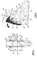
- the ski boot according to the present invention is of the type comprising a shell 12 and a boot leg 14 which extends above the shell 12.
- the boot leg 14 is hinged, in a known manner, to the shell 12 by means of a pin 16 which allows the boot to assume the two known operating positions corresponding to skiing (which is that shown in Figure 1) and that for walking (not shown) in which the boot leg 14 is opened, allowing the user to keep the legs substantially vertical.
- the boot leg 14 is provided in a known manner with means 18 for closing and locking the latter which, in Figure 1, are shown in the closed position.
- the means 18 are generally of the type with locking lever of a known type and are therefore not described in detail.
- the boot leg 14 is formed by a first and a second portion, respectively front 20 and rear 22 which, according to one of the characteristics of the boot according to the present invention, can be spread apart from each other, and more precisely in a mutually adjustable position, independently of whether the boot is in the condition of Figure 1 (corresponding to skiing) or in the condition corresponding to walking, that is to say, with the closure and locking means 18 disactivated (not shown).
- the front portion 20 of the boot leg 14 is sub-divided into two side pieces 24 which at the front define the opening 26 for the introduction of the foot of the skier, while at the rear they are connected to each other by a rear panel 28.
- the aforesaid side pieces 24 partially overlap the rear panel 28, and the latter in particular, as will be revealed more clearly hereinafter, constitutes the movable element of the boot leg for the spreading apart thereof, that is to say, its displaceable part, since the aforesaid side pieces 24 are stationary as part of the boot leg 14.
- the side pieces 24 and the rear panel 28 are expediently connected to one another, and with them there are associated cam means, described hereinafter, the actuation of which is such as to control displacements of the rear panel 28 with respect to the side pieces 24 so as to bring the former close to or away from the latter.
- the rear panel 28 is hinged at the bottom to the side pieces 24 by means of a pair of pins 30 (both visible in Figure 3) which are introduced into corresponding holes 32 in the panel 28 and in the side pieces 24.
- This type of connection allows in particular the rotation of the entire panel 28 about its lower end in both possible directions of rotation, as is particularly clear from Figures 1 and 3.
- the panel 28 and the side pieces 24 are also connected to one another by means which guide the rotation of the panel 28 with respect to the side pieces 24.
- Such means comprise a pin and slot connection wherein, in the exemplary embodiment under consideration, the pin 34 is arranged on the side piece 24 and its shank 36 projects in the direction of the panel 28 and is first introduced into a slit or slot 38 in the side piece 24, and then into a hole 40 in the panel 28.
- the slot 38 is more clearly visible in the cut-away region of Figure 4, from which it will be noted that the said slot 38 extends transversely on the side piece 24 in the direction of the rear panel 28. In this way, when the said panel 28 is caused to rotate in one direction or the other, the shank 36 of the pins 34 can slide freely in the said slot 38, thus allowing the rotational displacements of the panel 28.
- the ski boot according to the present invention further comprises cam means associated with each side piece 24 and with the rear panel 28, a portion of which, arranged so as to be displaceable in the side piece 24, is actuated directly by the user, there being associated with said portion a further portion co-operating with the rear panel which, when the portion arranged in the side piece 24 is actuated, controls the displacements of the rear panel 28.
- said cam means comprise firstly a first portion, arranged in the side piece 24 and displaceable therein, which is essential-ly constituted by a disc-like element 42 provided, on the visible face, with a recess 44 and which is received in a slot 46 provided in the side piece 24.
- the slot 46 is substantially rectangular in shape and has two rectilinear sides which are parallel and inclined upwards towards the front part of the boot and which are connected to each other at the ends by curved segments, in particular of essentially semicircular profile so as to receive the disc-like element 42, as can be seen in particular from Figure 1 and from the other analogous Figures illustrating the boot substantially in the same view, as well as from Figure 14.
- the disc-like element 42 which can be considered as an actuating button, can be caused to rotate in the slot 46 and simultaneously displaced longitudinally along the latter. It is sufficient, using any known tool such as a screwdriver or the like, to insert the head of the screwdriver into the recess 44 of the disc-like element 42 and to bring about its rotation. The latter, owing to the particular configuration of the slot 46, takes place along a substantially central axis of the disc-like element 42 while by means of the same tool a longitudinal displacement of the said disc-like element 42 is effected.
- This displacement in particular may be such as to bring the disc-like element 42 from one end of the slot 46, as shown in Figure 1 and in the analogous Figures, to the other end, as can be seen in Figure 14, completing a rotation of 180°.
- the disc-like element 42 during the aforesaid movement in translation, can be arrested in an intermediate position in the slot 46, the function of which will be described hereinafter.
- the disc-like element 42 is provided, on one of its faces, with a pin 48 substantially perpendicular to the body of the disc-like element 42 and, according to one of the principal characteristics of the boot according to the present invention, arranged eccentrically with respect to the aforesaid disc-like element 42.
- the rear panel 28 is provided, at the level of the slot 46, with a hole 50 capable of receiving the pin 48 when the disc-like element 42 is arranged in the slot 46. In this way, the disc-like element 42 and its pin 48 produce an eccentric connection between each side piece 24 and the rear panel 28.
- the aforesaid backward rotation is allowed both by the hinging by means of the pins 30 of the panel 28 to the side pieces 24, and by the pin 34/slot 38 connection between the side pieces 24 and the panel 28.
- the amplitude of the backward rotation of the panel 28 depends on the nature of the rotation and the movement in translation imparted to the disc-like element 42, which will then expediently transmit a backward pushing action by means of its pin 48.
- the action now described of course takes place on both sides of the boot leg, so that ultimately the said action is distributed in a uniform and balanced manner.
- the spreading apart of the boot leg 14 can be achieved both with the boot in the skiing condition (that is to say, with the closure and locking means 18 closed) and with the boot in the walking condition (that is to say, with the closure and locking means 18 disabled).
- the boot can be returned to the starting condition, that is to say, that shown in Figure 1, by operating in the opposite direction to the preceding direction.
- Figures 7 and 9 respectively show more precisely two possible positions of the disc-like element 42, in the first of which ( Figure 7) the panel 28 is in the position closest to the side piece 24, while in the second ( Figure 9) the panel 28 has been moved back with respect to the side piece 24 owing to the action of the cam means with which the boot according to the present invention is provided.
- Figures 11, 13, and 15 are views analogous to Figures 7 and 9, which represent the cam means of the boot accord-ing to the present invention in the different successive operating positions. More precisely, in the condition in Figure 11, the cam means mentioned above are arranged so as to maintain the panel 28 in the position closest to the side pieces 24. In Figure 3, by means of rotation still in the direction of the arrow G, the disc-like element 42 is caused to rotate to bring about the backward rotation of the panel 28 as indicated diagrammatically in Figure 12. Finally, in Figure 15, the rotation of the disc-like element 42 ends, so that the panel is in the position of maximum spreading apart with respect to the side piece 24, as illustrated diagrammatically in Figure 15.
- FIGS 11, 13 and 15 show diagrammatically in succession in the various operating positions the pin 48 with which the disc-like element 42 is provided.
- the cam means mentioned above function as a control lever which transmits the movement to the panel 28 from the disc-like element 42.
- the latter in particular is comparable to the fulcrum of the aforesaid lever and in particular is a movable fulcrum in so far as during the operating step of displacement of the panel 28, the latter is caused to rotate and to move in translation in the slot 46. This clearly applies both in the step of actual spreading apart of the boot leg of the boot and in the step of returning the latter to the initial condition.
Landscapes
- Health & Medical Sciences (AREA)
- General Health & Medical Sciences (AREA)
- Physical Education & Sports Medicine (AREA)
- Footwear And Its Accessory, Manufacturing Method And Apparatuses (AREA)
- Golf Clubs (AREA)
- Sealing Devices (AREA)
Applications Claiming Priority (2)
| Application Number | Priority Date | Filing Date | Title |
|---|---|---|---|
| IT1996TV000059U IT242131Y1 (it) | 1996-09-20 | 1996-09-20 | Scarpone da sci comprendente uno scafo ed un gambetto incernierati traloro in cui il gambetto e' realizzato in due porzioni divaricabili tra |
| ITTV960059U | 1996-09-20 |
Publications (3)
| Publication Number | Publication Date |
|---|---|
| EP0830821A2 true EP0830821A2 (fr) | 1998-03-25 |
| EP0830821A3 EP0830821A3 (fr) | 1999-01-27 |
| EP0830821B1 EP0830821B1 (fr) | 2002-01-23 |
Family
ID=11419915
Family Applications (1)
| Application Number | Title | Priority Date | Filing Date |
|---|---|---|---|
| EP97202625A Expired - Lifetime EP0830821B1 (fr) | 1996-09-20 | 1997-08-27 | Chaussure de ski avec une tige formée de deux parties pouvant être écartées |
Country Status (6)
| Country | Link |
|---|---|
| US (1) | US5875570A (fr) |
| EP (1) | EP0830821B1 (fr) |
| JP (1) | JPH1099102A (fr) |
| AT (1) | ATE212197T1 (fr) |
| DE (1) | DE69710013T2 (fr) |
| IT (1) | IT242131Y1 (fr) |
Cited By (1)
| Publication number | Priority date | Publication date | Assignee | Title |
|---|---|---|---|---|
| US9241532B2 (en) | 2012-01-04 | 2016-01-26 | K-2 Corporation | Ski/walk mechanism |
Families Citing this family (5)
| Publication number | Priority date | Publication date | Assignee | Title |
|---|---|---|---|---|
| FR2776896B1 (fr) * | 1998-04-03 | 2000-06-30 | Salomon Sa | Chaussure de sport a ossature rigide partiellement recouverte |
| US6543793B1 (en) | 2000-10-03 | 2003-04-08 | The Burton Corporation | Highback formed of multiple materials |
| AU2634401A (en) | 2000-01-06 | 2001-07-16 | Burton Corporation, The | Highback formed of multiple materials |
| EP2116145B1 (fr) * | 2008-05-08 | 2012-12-05 | OBER ALP S.p.A. | Chaussure de ski, en particulier pour le ski de randonnée |
| CN105288989B (zh) * | 2015-10-30 | 2018-07-17 | 宁波金峰文体器材有限公司 | 便于穿脱的轮滑鞋鞋壳 |
Family Cites Families (16)
| Publication number | Priority date | Publication date | Assignee | Title |
|---|---|---|---|---|
| FR2527908A1 (fr) * | 1982-06-02 | 1983-12-09 | Salomon & Fils F | Dispositif de reglage d'une chaussure de ski |
| FR2575045B1 (fr) * | 1984-12-20 | 1987-01-23 | Salomon Sa | Chaussure de ski alpin |
| FR2622776B1 (fr) * | 1987-11-10 | 1990-03-23 | Salomon Sa | Chaussure de ski alpin a tige articulee sur un bas de coque |
| IT1222288B (it) * | 1988-05-20 | 1990-09-05 | Nordica Spa | Scarpone da sci a calzabilita' migliorata |
| CH677589A5 (fr) * | 1988-11-30 | 1991-06-14 | Lange Int Sa | |
| FR2640123B1 (fr) * | 1988-12-09 | 1991-08-23 | Salomon Sa | Chaussure de ski alpin |
| CH680557A5 (fr) * | 1989-08-28 | 1992-09-30 | Lange Int Sa | |
| IT1240266B (it) * | 1990-01-15 | 1993-11-30 | Nordica Spa | Dispositivo di appoggio posteriore regolabile,particolarmente per scarponi da sci |
| FR2663515A1 (fr) * | 1990-06-26 | 1991-12-27 | Rossignol Sa | Chaussure de ski en matiere plastique. |
| IT223064Z2 (it) * | 1990-09-27 | 1995-06-09 | Nordica Spa | Struttura di dispositivo di regolazione dell'appoggio posteriore particolarmente per scarponi da sci |
| FR2673081B1 (fr) * | 1991-02-26 | 1994-11-18 | Rossignol Sa | Chaussure de ski a coque et collier. |
| FR2682859A1 (fr) * | 1991-10-28 | 1993-04-30 | Salomon Sa | Chaussure de ski comportant des moyens de reglage de la flexion longitudinale. |
| CH688635A5 (fr) * | 1993-04-02 | 1997-12-31 | Lange Int Sa | Chaussure de ski. |
| EP0657114B1 (fr) * | 1993-12-07 | 1998-10-21 | TECNICA S.p.A | Chaussure de ski avec rembourrage amélioré et languette glissante |
| CH689630A5 (fr) * | 1994-03-10 | 1999-07-30 | Lange Int Sa | Chaussure de ski en matière synthétique. |
| FR2732562B1 (fr) * | 1995-04-06 | 1997-05-23 | Salomon Sa | Chaussure de sport a tige reglable |
-
1996
- 1996-09-20 IT IT1996TV000059U patent/IT242131Y1/it active
-
1997
- 1997-08-15 US US08/912,238 patent/US5875570A/en not_active Expired - Lifetime
- 1997-08-27 DE DE69710013T patent/DE69710013T2/de not_active Expired - Lifetime
- 1997-08-27 AT AT97202625T patent/ATE212197T1/de active
- 1997-08-27 EP EP97202625A patent/EP0830821B1/fr not_active Expired - Lifetime
- 1997-09-22 JP JP9256751A patent/JPH1099102A/ja active Pending
Cited By (1)
| Publication number | Priority date | Publication date | Assignee | Title |
|---|---|---|---|---|
| US9241532B2 (en) | 2012-01-04 | 2016-01-26 | K-2 Corporation | Ski/walk mechanism |
Also Published As
| Publication number | Publication date |
|---|---|
| DE69710013D1 (de) | 2002-03-14 |
| IT242131Y1 (it) | 2001-06-04 |
| ATE212197T1 (de) | 2002-02-15 |
| JPH1099102A (ja) | 1998-04-21 |
| US5875570A (en) | 1999-03-02 |
| ITTV960059U1 (it) | 1998-03-20 |
| DE69710013T2 (de) | 2002-09-05 |
| EP0830821B1 (fr) | 2002-01-23 |
| ITTV960059V0 (it) | 1996-09-20 |
| EP0830821A3 (fr) | 1999-01-27 |
Similar Documents
| Publication | Publication Date | Title |
|---|---|---|
| US4222184A (en) | Ski boot | |
| EP0232801B1 (fr) | Dispositif de fermeture de quartiers, en particulier de chaussures de ski | |
| US5003711A (en) | Alpine ski boot | |
| US4694592A (en) | Closure device particularly for rear entrance ski boots | |
| JPS60259203A (ja) | 足固定装置を備えたスキーブーツ | |
| JPH0580201B2 (fr) | ||
| EP0830821B1 (fr) | Chaussure de ski avec une tige formée de deux parties pouvant être écartées | |
| JPS62114501A (ja) | 後方插入型スキ−靴 | |
| JPH0381362B2 (fr) | ||
| EP0512582A1 (fr) | Dispositif de fermeture et d'ajustement, en particulier pour chaussure de ski | |
| US5134792A (en) | Read-fitting ski boot | |
| JPH01198501A (ja) | 胴部のヒンジ連結軸の傾斜調節装置を含む靴 | |
| EP0174000A1 (fr) | Structure de dispositif pour varier l'inclinaison de chaussures de ski | |
| JPH03191901A (ja) | スキー靴 | |
| US5065530A (en) | Closure device, particularly for ski boots | |
| US5381613A (en) | Ski boot | |
| US5107609A (en) | Ski boot with improved fit | |
| EP0134562A1 (fr) | Dispositif de blocage du pied, en particulier pour chaussures de ski à entrée avant | |
| US4949480A (en) | Ski boot | |
| US5020248A (en) | Ski boot | |
| JPH0399601A (ja) | 特にスキー靴用の調節可能な閉鎖装置 | |
| JPH04244101A (ja) | 胴部にヒンジ連結した硬直化用部材を有するリヤエントリー式アルペンスキー靴 | |
| JPH0576401A (ja) | 後部覆い上にヒンジ連結したエネルギー付加用鐙形部材を有するアルペンスキー靴 | |
| US5826355A (en) | Ski boot having a combined closure and heel-engaging member | |
| JPH04226602A (ja) | 調整可能な後部サポートプレートを備えたスキーブーツ |
Legal Events
| Date | Code | Title | Description |
|---|---|---|---|
| PUAI | Public reference made under article 153(3) epc to a published international application that has entered the european phase |
Free format text: ORIGINAL CODE: 0009012 |
|
| AK | Designated contracting states |
Kind code of ref document: A2 Designated state(s): AT CH DE FR IT LI |
|
| PUAL | Search report despatched |
Free format text: ORIGINAL CODE: 0009013 |
|
| AK | Designated contracting states |
Kind code of ref document: A3 Designated state(s): AT BE CH DE DK ES FI FR GB GR IE IT LI LU MC NL PT SE |
|
| 17P | Request for examination filed |
Effective date: 19990715 |
|
| AKX | Designation fees paid |
Free format text: AT CH DE FR IT LI |
|
| GRAG | Despatch of communication of intention to grant |
Free format text: ORIGINAL CODE: EPIDOS AGRA |
|
| 17Q | First examination report despatched |
Effective date: 20010810 |
|
| GRAG | Despatch of communication of intention to grant |
Free format text: ORIGINAL CODE: EPIDOS AGRA |
|
| GRAH | Despatch of communication of intention to grant a patent |
Free format text: ORIGINAL CODE: EPIDOS IGRA |
|
| GRAH | Despatch of communication of intention to grant a patent |
Free format text: ORIGINAL CODE: EPIDOS IGRA |
|
| GRAA | (expected) grant |
Free format text: ORIGINAL CODE: 0009210 |
|
| AK | Designated contracting states |
Kind code of ref document: B1 Designated state(s): AT CH DE FR IT LI |
|
| PG25 | Lapsed in a contracting state [announced via postgrant information from national office to epo] |
Ref country code: FR Free format text: LAPSE BECAUSE OF FAILURE TO SUBMIT A TRANSLATION OF THE DESCRIPTION OR TO PAY THE FEE WITHIN THE PRESCRIBED TIME-LIMIT Effective date: 20020123 |
|
| REF | Corresponds to: |
Ref document number: 212197 Country of ref document: AT Date of ref document: 20020215 Kind code of ref document: T |
|
| REG | Reference to a national code |
Ref country code: CH Ref legal event code: EP |
|
| REF | Corresponds to: |
Ref document number: 69710013 Country of ref document: DE Date of ref document: 20020314 |
|
| REG | Reference to a national code |
Ref country code: CH Ref legal event code: NV Representative=s name: ZIMMERLI, WAGNER & PARTNER AG |
|
| EN | Fr: translation not filed | ||
| PLBE | No opposition filed within time limit |
Free format text: ORIGINAL CODE: 0009261 |
|
| STAA | Information on the status of an ep patent application or granted ep patent |
Free format text: STATUS: NO OPPOSITION FILED WITHIN TIME LIMIT |
|
| 26N | No opposition filed | ||
| PG25 | Lapsed in a contracting state [announced via postgrant information from national office to epo] |
Ref country code: IT Free format text: LAPSE BECAUSE OF NON-PAYMENT OF DUE FEES Effective date: 20070827 |
|
| REG | Reference to a national code |
Ref country code: CH Ref legal event code: PFA Owner name: TECNICA SPA Free format text: TECNICA SPA#VIA FANTE D'ITALIA 56#I-31040 GIAVERA DEL MONTELLO (TREVISO) (IT) -TRANSFER TO- TECNICA SPA#VIA FANTE D'ITALIA 56#I-31040 GIAVERA DEL MONTELLO (TREVISO) (IT) |
|
| PGFP | Annual fee paid to national office [announced via postgrant information from national office to epo] |
Ref country code: AT Payment date: 20100722 Year of fee payment: 14 |
|
| PGFP | Annual fee paid to national office [announced via postgrant information from national office to epo] |
Ref country code: IT Payment date: 20110825 Year of fee payment: 15 |
|
| REG | Reference to a national code |
Ref country code: AT Ref legal event code: MM01 Ref document number: 212197 Country of ref document: AT Kind code of ref document: T Effective date: 20110827 |
|
| PG25 | Lapsed in a contracting state [announced via postgrant information from national office to epo] |
Ref country code: AT Free format text: LAPSE BECAUSE OF NON-PAYMENT OF DUE FEES Effective date: 20110827 |
|
| PG25 | Lapsed in a contracting state [announced via postgrant information from national office to epo] |
Ref country code: IT Free format text: LAPSE BECAUSE OF NON-PAYMENT OF DUE FEES Effective date: 20120827 |
|
| PGFP | Annual fee paid to national office [announced via postgrant information from national office to epo] |
Ref country code: CH Payment date: 20130826 Year of fee payment: 17 Ref country code: DE Payment date: 20130823 Year of fee payment: 17 |
|
| REG | Reference to a national code |
Ref country code: CH Ref legal event code: NV Representative=s name: WAGNER PATENT AG, CH |
|
| REG | Reference to a national code |
Ref country code: DE Ref legal event code: R119 Ref document number: 69710013 Country of ref document: DE |
|
| REG | Reference to a national code |
Ref country code: CH Ref legal event code: PL |
|
| PG25 | Lapsed in a contracting state [announced via postgrant information from national office to epo] |
Ref country code: LI Free format text: LAPSE BECAUSE OF NON-PAYMENT OF DUE FEES Effective date: 20140831 Ref country code: CH Free format text: LAPSE BECAUSE OF NON-PAYMENT OF DUE FEES Effective date: 20140831 |
|
| REG | Reference to a national code |
Ref country code: DE Ref legal event code: R119 Ref document number: 69710013 Country of ref document: DE Effective date: 20150303 |
|
| PG25 | Lapsed in a contracting state [announced via postgrant information from national office to epo] |
Ref country code: DE Free format text: LAPSE BECAUSE OF NON-PAYMENT OF DUE FEES Effective date: 20150303 |