EP0831224A2 - Agencement de capteurs pour identifier rapidement un cylindre dans uns moteur à combustion interne - Google Patents
Agencement de capteurs pour identifier rapidement un cylindre dans uns moteur à combustion interne Download PDFInfo
- Publication number
- EP0831224A2 EP0831224A2 EP97114153A EP97114153A EP0831224A2 EP 0831224 A2 EP0831224 A2 EP 0831224A2 EP 97114153 A EP97114153 A EP 97114153A EP 97114153 A EP97114153 A EP 97114153A EP 0831224 A2 EP0831224 A2 EP 0831224A2
- Authority
- EP
- European Patent Office
- Prior art keywords
- encoder
- angle
- crankshaft
- mark
- marks
- Prior art date
- Legal status (The legal status is an assumption and is not a legal conclusion. Google has not performed a legal analysis and makes no representation as to the accuracy of the status listed.)
- Granted
Links
Images



Classifications
-
- F—MECHANICAL ENGINEERING; LIGHTING; HEATING; WEAPONS; BLASTING
- F02—COMBUSTION ENGINES; HOT-GAS OR COMBUSTION-PRODUCT ENGINE PLANTS
- F02D—CONTROLLING COMBUSTION ENGINES
- F02D41/00—Electrical control of supply of combustible mixture or its constituents
- F02D41/009—Electrical control of supply of combustible mixture or its constituents using means for generating position or synchronisation signals
-
- F—MECHANICAL ENGINEERING; LIGHTING; HEATING; WEAPONS; BLASTING
- F02—COMBUSTION ENGINES; HOT-GAS OR COMBUSTION-PRODUCT ENGINE PLANTS
- F02D—CONTROLLING COMBUSTION ENGINES
- F02D41/00—Electrical control of supply of combustible mixture or its constituents
- F02D41/02—Circuit arrangements for generating control signals
- F02D41/04—Introducing corrections for particular operating conditions
- F02D41/06—Introducing corrections for particular operating conditions for engine starting or warming up
- F02D41/062—Introducing corrections for particular operating conditions for engine starting or warming up for starting
Definitions
- the invention relates to an encoder arrangement for fast Cylinder detection in a multi-cylinder Internal combustion engine according to the type of the main claim.
- crankshaft sensors and a camshaft sensor these sensors with the crankshaft and the camshaft connected encoder disks with a characteristic Scan the surface and output signals to the control unit deliver that carries out the required evaluations and Trigger pulses triggered.
- the two encoder disks are more suitable with the help Sensor scanned.
- the output signals of these sensors are evaluated in the control unit and when generating Ignition and injection pulses taken into account.
- the encoder arrangement according to the invention for fast Has cylinder detection in an internal combustion engine has the advantage that one more faster and more reliable cylinder detection can be carried out at the start. Because of the advantageous Design of the encoder disks or the associated ones Angle marks are different types of systems can be used, for example inductive sensors, Hall sensors, capacitive sensors or with a corresponding modification also optical sensors.
- the encoder disk connected to the internal combustion engine has two reference marks that are opposite each other or by using a number of fiducials, which corresponds to the number of cylinders in the internal combustion engine.
- the connected to the camshaft of the internal combustion engine Encoder disc has a so-called segment angle mark pro Number of cylinders Z, the distances between the segment angle marks are the same.
- Z is minus 1 segment angle marks each assigned a synchronization angle mark, where the distances between the segment angle marks and the associated synchronization angle marks different are.
- the encoder arrangement according to the invention for fast Cylinder detection in a multi-cylinder Internal combustion engine can both advantageously for diesel and also spark-ignited internal combustion engines deploy.
- diesel engines with EDC systems the injection can be based on that of the claimed Signals delivered after very early on the start of the internal combustion engine and also in the further Regulate the course of operation of the internal combustion engine.
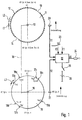
- Figure 1 is an embodiment of the invention shown schematically, being from the internal combustion engine only the parts essential to the invention are specified.
- Figure 1 shows a rigid with the crankshaft 10 connected encoder disk 11, which has a number on its circumference of the same angle marks 12.
- the angle marks 12 extend over a length L1 and face each other a distance L2.
- Two reference marks 13, 14 are marked by two missing angle marks were formed. They lie to each other on the encoder disc opposite.
- the length L1 of the Angle marks is in the correct ratio, e.g. B. to the pole core of the associated transducer.
- a second encoder disk 15 is connected to the camshaft 16 Internal combustion engine connected and points to its scope Segment angle marks 17 on, with a length L3.
- segment angle marks 17a, 17b, 17c, 17d are further synchronization angle marks 18a, 18b, 18c present, one of each Synchronization angle marks of a segment angle mark is assigned and the distances between the segment angle marks and the synchronization angle marks are of different lengths.
- One of the segment angle marks is in the embodiment of the segment angle mark 17d no synchronization angle mark assigned.
- the camshaft 16 of the internal combustion engine is operated by the Crankshaft 10 driven and rotated in the usual way at half the speed of the crankshaft 10.
- the rigid connection between crankshaft 10 and camshaft 16 is symbolized by line 19.
- the encoder disks run the angle marks past sensors 20 and 21. In the transducers this creates tensions that affect the surface of the Play encoder disks.
- the encoder disk 11 and the Pickups 20 are also used as crankshaft sensors and Sensor disc 15 with the sensor 21 as a camshaft sensor designated.
- Inductive sensors, Hall sensors, capacitive transducers or with a corresponding adjustment also use optical sensors, these optical Sensors then consist of a transmitter and a receiver and there are angular marks between these two elements move.
- the direction of rotation of the shafts or disks is each indicated by an arrow.
- the signals of the Pickups 20 and 21 are designated S1 and S2. she are fed to a control unit 22, in which at least a computing device, for example a microprocessor including the associated memory. in the Control unit, the signal curves are evaluated.
- an EDC control unit run for the regulation of the internal combustion engine required Calculations based on the data from the sensors 20, 21 delivered signals S1 and S2.
- the control unit further information supplied by corresponding Sensors are supplied and via corresponding inputs E1 be fed.
- the control unit outputs A1, for example Injection pulses to the injectors 24.
- the Power is supplied via the switch 25 through the Battery 26.
- each cylinder of the internal combustion engine Segment angle mark on the assigned to the camshaft 16 Assigned encoder disc 15.
- Get three of the four cylinders additionally one in one for the cylinder characteristic distance to the segment angle mark arranged synchronization angle mark.
- At one of the No synchronization angle mark is placed on the cylinder, but only a segment angle mark.
- the position of the encoder disks relative to each other can be Synchronization angle mark a certain Crankshaft encoder disc angle mark 12 can be assigned. This is a clear cylinder detection and thus synchronization of the crankshaft encoder disk possible.
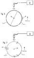
- FIGS. 2 and 3 specified signal profiles, or relationships between Signals and encoder disc surface.
- Figure 2 is based the example of the camshaft segment of cylinder 2 shows how the signals are generated.
- the surface of the encoder disk 15 in Figure 2a Area of the segment mark 17c, or the synchronization angle mark 18c shown.
- the distance between the Segment angle mark 17b and the synchronization angle mark 18b is 18 ° NW (i.e. related to the camshaft).
- the Direction of rotation is symbolized by an arrow.
- FIG 2b is the associated signal curve S2, which the pickup 21 delivers, represented. From this waveform the Figure 2c shown square wave signal that ultimately to Synchronization is used, formed.
- the surface of the encoder disk 11 is shown in FIG. 2d with the angle marks 12 and the reference mark 14.
- the signal S1 is generated that in Figure 2e is specified.
- This signal S1 becomes the rectangular one Signal that is shown in Figure 2f formed.
- the education of square wave signals from sinusoidal signals takes place in generally known manner. For example, in a the evaluation circuit assigned to the transducer or in Control unit 22 take place.
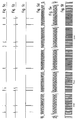
- FIG. 3 the processed signals are above Crankshaft angle plotted, the crankshaft angle is given in degrees OT.
- Figure 3a that is from the Scanning the multitude of angle marks on the So-called crankshaft encoder disk obtained Incremental signal that occurs when using a crankshaft encoder disc 11 according to FIG. 1 results. This Increment signal is at the input of the control unit integrated angle clock.
- Figure 3b is the processed Camshaft sensor signal, which at the input of the computer of the Control unit 22 is present for the various Areas of the camshaft sensor disk assigned to respective cylinders shown.
- FIG. 3c shows in which crankshaft angle tolerance range the camshaft sensor signals may occur so that they are still clear can be assigned.
- the reference mark lies due to boundary conditions 1 and 4 between the preferred position of the internal combustion engine and the the next but one ignition TDC.
- the maximum Total tolerance of the position of the camshaft pulses to the Crankshaft pulses should be less than +/- 9 ° KW.
- This Total tolerance is made up of the Manufacturing tolerances of the angle marks and the Mounting tolerances of the two encoder disks from which Angle of rotation between crankshaft 10 and camshaft 16 and from inaccuracies in the signal acquisition and from the Processing time of the computer.
- FIG. 4 shows the sequence of the camshaft sensor signals.
- FIG. 5 shows those already shown with reference to FIG. 2 Encoder disk configurations, or signals via a shown larger crankshaft angle range.
- the associated system of a quick start encoder disk configuration for one Four-cylinder internal combustion engine is through synchronization angle marks able on the camshaft encoder disc quickly recognize the current cylinder. This is through Querying the position of the synchronization angle mark to be checked realized in the cylinder segment. Will a location identified from several possible, then this location, defined by an upper and a lower limit, in Data record that is stored in the computer of the control unit Assigned cylinder. If a cylinder is identified, it runs then a cylinder counter.
- This cylinder counter is running in a four-cylinder internal combustion engine from zero to three. In general, Z cylinders are counted up to Z-1. By checking the correctness of this process can be further information regarding the functionality of the System. To determine whether the process is correct is, the position of the Synchronization angle marks checked. The determined Meter reading indicates a specific location of the Synchronization angle mark, which is stored in the data record is. If the angle mark that occurs has this target position, classified them as plausible. Is it in a position other than that determined by the cylinder counter and with a lower and upper limit position defined in the data set, the relevant synchronization angle mark is used as classified incorrectly and possibly a malfunction of the system recognized and displayed.
- crankshaft encoder disk the camshaft sensor disk and the associated waveforms for a 3 cylinder Internal combustion engine specified.
- the one with the crankshaft connected encoder disc has a reference mark for every cylinder.
Landscapes
- Engineering & Computer Science (AREA)
- Chemical & Material Sciences (AREA)
- Combustion & Propulsion (AREA)
- Mechanical Engineering (AREA)
- General Engineering & Computer Science (AREA)
- Combined Controls Of Internal Combustion Engines (AREA)
- Measurement Of Length, Angles, Or The Like Using Electric Or Magnetic Means (AREA)
- Length Measuring Devices By Optical Means (AREA)
- Length Measuring Devices With Unspecified Measuring Means (AREA)
- Transmission And Conversion Of Sensor Element Output (AREA)
Applications Claiming Priority (2)
| Application Number | Priority Date | Filing Date | Title |
|---|---|---|---|
| DE19638338 | 1996-09-19 | ||
| DE19638338A DE19638338A1 (de) | 1996-09-19 | 1996-09-19 | Geberanordnung zur schnellen Zylindererkennung bei einer Brennkraftmaschine |
Publications (3)
| Publication Number | Publication Date |
|---|---|
| EP0831224A2 true EP0831224A2 (fr) | 1998-03-25 |
| EP0831224A3 EP0831224A3 (fr) | 1999-10-20 |
| EP0831224B1 EP0831224B1 (fr) | 2001-10-24 |
Family
ID=7806192
Family Applications (1)
| Application Number | Title | Priority Date | Filing Date |
|---|---|---|---|
| EP97114153A Expired - Lifetime EP0831224B1 (fr) | 1996-09-19 | 1997-08-16 | Agencement de capteurs pour identifier rapidement un cylindre dans un moteur à combustion interne |
Country Status (3)
| Country | Link |
|---|---|
| EP (1) | EP0831224B1 (fr) |
| JP (1) | JP3949236B2 (fr) |
| DE (2) | DE19638338A1 (fr) |
Cited By (6)
| Publication number | Priority date | Publication date | Assignee | Title |
|---|---|---|---|---|
| EP1111204A3 (fr) * | 1999-11-27 | 2002-11-06 | Dr.Ing. h.c.F. Porsche Aktiengesellschaft | Commande de soupapes |
| FR2839748A1 (fr) * | 2002-05-14 | 2003-11-21 | Siemens Ag | Procede et dispositif de demarrage d'un moteur a combustion interne a plusieurs cylindres |
| WO2017065672A1 (fr) * | 2015-10-16 | 2017-04-20 | Scania Cv Ab | Procédé et système de diagnostic pour une unité de capteur de position de rotation de vilebrequin |
| WO2018117930A1 (fr) * | 2016-12-19 | 2018-06-28 | Scania Cv Ab | Détection de cylindre dans un moteur à combustion interne à quatre temps |
| WO2020084055A1 (fr) * | 2018-10-24 | 2020-04-30 | Continental Automotive France | Procédé de synchronisation d'un moteur à combustion |
| CN115653768A (zh) * | 2022-10-27 | 2023-01-31 | 江门市大长江集团有限公司 | 摩托车双缸发动机的控制方法、装置和系统 |
Families Citing this family (14)
| Publication number | Priority date | Publication date | Assignee | Title |
|---|---|---|---|---|
| DE19741597A1 (de) * | 1997-09-20 | 1999-03-25 | Schaeffler Waelzlager Ohg | Nockenpulsrad für eine Brennkraftmaschine mit variabler Nockenwellensteuerung |
| JP4466929B2 (ja) | 1998-06-03 | 2010-05-26 | 株式会社ケーヒン | 回転体の回転角度位置検出装置 |
| KR100335927B1 (ko) * | 1999-07-21 | 2002-05-09 | 이계안 | 크랭크 각도 신호 처리장치 및 그 처리 방법 |
| KR100356661B1 (ko) * | 1999-09-15 | 2002-10-19 | 기아자동차주식회사 | 자동차의 실린더 판별 장치의 캠 타겟 휠 |
| FR2802242B1 (fr) * | 1999-12-10 | 2002-05-10 | Siemens Automotive Sa | Procede de determination de la position moteur et dispositif correspondant |
| JP3506116B2 (ja) * | 2000-01-27 | 2004-03-15 | 株式会社デンソー | エンジン制御装置 |
| JP3794485B2 (ja) * | 2002-06-26 | 2006-07-05 | 三菱電機株式会社 | 内燃機関の気筒判別装置 |
| JP3768927B2 (ja) * | 2002-07-10 | 2006-04-19 | 三菱電機株式会社 | 内燃機関の気筒判別装置 |
| JP3786269B2 (ja) * | 2002-11-06 | 2006-06-14 | 三菱電機株式会社 | 内燃機関のクランク角度検出装置 |
| DE10313219B4 (de) * | 2003-03-25 | 2017-05-11 | Robert Bosch Gmbh | Verfahren zum Betreiben einer Brennkraftmaschine |
| DE102004035199B3 (de) * | 2004-07-21 | 2006-03-30 | Siemens Ag | Verfahren zum Bestimmen der Winkelposition einer Brennkraftmaschine zum zeitgerechten Steuern der zweiten Verbrennung beim Start |
| ITPI20080042A1 (it) * | 2008-05-15 | 2009-11-16 | Domenico Morello | Supporto per televisore a schermo piatto |
| JP7730823B2 (ja) * | 2020-08-19 | 2025-08-28 | マーレ インターナショナル ゲゼルシャフト ミット ベシュレンクテル ハフツング | エンジン用信号発生装置 |
| DE102023207081A1 (de) | 2023-07-25 | 2025-01-30 | Robert Bosch Gesellschaft mit beschränkter Haftung | Brennkraftmaschine |
Family Cites Families (6)
| Publication number | Priority date | Publication date | Assignee | Title |
|---|---|---|---|---|
| DE3608321A1 (de) * | 1986-03-13 | 1987-09-17 | Pierburg Gmbh & Co Kg | Einrichtung zum erfassen der zylinderbezogenen kurbelwellenstellung |
| JPH03145547A (ja) * | 1989-10-30 | 1991-06-20 | Mitsubishi Electric Corp | 内燃機関制御方法 |
| US5156125A (en) * | 1990-10-11 | 1992-10-20 | Mitsubishi Denki Kabushiki Kaisha | Engine control apparatus |
| DE4141713C2 (de) * | 1991-12-18 | 2003-11-06 | Bosch Gmbh Robert | Geberanordnung zur Zylindererkennung und zum Notlaufbetrieb bei einer Brennkraftmaschine mit n Zylindern |
| DE4243177C2 (de) * | 1992-12-19 | 2003-08-28 | Bosch Gmbh Robert | Einrichtung zur schnellen Zylindererkennung bei einer Brennkraftmaschine |
| IT1261576B (it) * | 1993-09-03 | 1996-05-23 | Fiat Ricerche | Sistema di sincronizzazione di un motore a combustione interna |
-
1996
- 1996-09-19 DE DE19638338A patent/DE19638338A1/de not_active Ceased
-
1997
- 1997-08-16 EP EP97114153A patent/EP0831224B1/fr not_active Expired - Lifetime
- 1997-08-16 DE DE59705056T patent/DE59705056D1/de not_active Expired - Lifetime
- 1997-09-18 JP JP25387597A patent/JP3949236B2/ja not_active Expired - Fee Related
Cited By (12)
| Publication number | Priority date | Publication date | Assignee | Title |
|---|---|---|---|---|
| EP1111204A3 (fr) * | 1999-11-27 | 2002-11-06 | Dr.Ing. h.c.F. Porsche Aktiengesellschaft | Commande de soupapes |
| FR2839748A1 (fr) * | 2002-05-14 | 2003-11-21 | Siemens Ag | Procede et dispositif de demarrage d'un moteur a combustion interne a plusieurs cylindres |
| WO2017065672A1 (fr) * | 2015-10-16 | 2017-04-20 | Scania Cv Ab | Procédé et système de diagnostic pour une unité de capteur de position de rotation de vilebrequin |
| WO2018117930A1 (fr) * | 2016-12-19 | 2018-06-28 | Scania Cv Ab | Détection de cylindre dans un moteur à combustion interne à quatre temps |
| CN110139978A (zh) * | 2016-12-19 | 2019-08-16 | 斯堪尼亚商用车有限公司 | 四冲程内燃机中的汽缸检测 |
| US11585287B2 (en) | 2016-12-19 | 2023-02-21 | Scania Cv Ab | Cylinder detection in a four-stroke internal combustion engine |
| WO2020084055A1 (fr) * | 2018-10-24 | 2020-04-30 | Continental Automotive France | Procédé de synchronisation d'un moteur à combustion |
| FR3087838A1 (fr) * | 2018-10-24 | 2020-05-01 | Continental Automotive France | Procede de synchronisation d'un moteur a combustion |
| CN113167183A (zh) * | 2018-10-24 | 2021-07-23 | 纬湃科技有限责任公司 | 用于同步内燃发动机的方法 |
| CN113167183B (zh) * | 2018-10-24 | 2023-03-14 | 纬湃科技有限责任公司 | 同步机动车辆的内燃发动机的方法、车辆的计算机及机动车辆 |
| US11668257B2 (en) | 2018-10-24 | 2023-06-06 | Vitesco Technologies GmbH | Method for synchronising a combustion engine |
| CN115653768A (zh) * | 2022-10-27 | 2023-01-31 | 江门市大长江集团有限公司 | 摩托车双缸发动机的控制方法、装置和系统 |
Also Published As
| Publication number | Publication date |
|---|---|
| JP3949236B2 (ja) | 2007-07-25 |
| JPH10103946A (ja) | 1998-04-24 |
| DE59705056D1 (de) | 2001-11-29 |
| EP0831224A3 (fr) | 1999-10-20 |
| DE19638338A1 (de) | 1998-04-02 |
| EP0831224B1 (fr) | 2001-10-24 |
Similar Documents
| Publication | Publication Date | Title |
|---|---|---|
| EP0831224B1 (fr) | Agencement de capteurs pour identifier rapidement un cylindre dans un moteur à combustion interne | |
| EP0643803B1 (fr) | Agencement de capteurs permettant d'identifier rapidement un cylindre dans un moteur polycylindrique a combustion interne | |
| EP0572584B1 (fr) | Systeme de capteurs pour l'identification des cylindres dans un moteur a combustion interne | |
| DE4440656B4 (de) | Variable Nockenwelleneinstellvorrichtung | |
| DE4037546C2 (de) | Zylinderidentifikationsvorrichtung | |
| EP0607177B1 (fr) | Agencement de detection de la position angulaire d'une piece rotative | |
| EP1045967B1 (fr) | Dispositif de reconnaissance de phase | |
| EP0862692A1 (fr) | Procede permettant de determiner l'angle de phase d'un moteur a combustion interne a quatre temps et a nombre impair de cylindres | |
| DE4434833A1 (de) | Einrichtung zur Erkennung des Rückdrehens eines rotierenden Teiles einer Brennkraftmaschine | |
| EP0638717B1 (fr) | Dispositif pour commander l'injection en carburant et l'allumage d'un moteur à combustion | |
| DE69916547T2 (de) | Verfahren zur Synchronisation einer Brennkraftmaschine | |
| DE3932075C2 (de) | Verfahren zur Erkennung eines Bezugszylinders bei einer Mehrzylinder-Brennkraftmaschine und Vorrichtung zur Durchführung des Verfahrens | |
| EP1070964A2 (fr) | Dispositif de reconnaissance de la rotation inverse d'une partie tournante d'un moteur à combustion interne | |
| DE10329586A1 (de) | Kurbelwinkeldetektoreinrichtung für Brennkraftmaschinen | |
| WO2001048488A2 (fr) | Procede et dispositif de reconnaissance d'une inversion de polarite d'un detecteur de signaux | |
| EP0931212A1 (fr) | Procede de determination de temps segmentaires | |
| EP0898070B1 (fr) | Méthode pour identifier la phase de combustion d'un cylindre déterminé pendant le démarrage d'un moteur à combustion interne | |
| DE4241683A1 (fr) | ||
| DE4011503A1 (de) | Vorrichtung zur erfassung eines rotierenden teils einer brennkraftmaschine | |
| DE68922309T2 (de) | Verfahren und Vorrichtung für die Detektierung eines Referenzdrehwinkels für jeden Zylinder in einer inneren Brennkraftmaschine. | |
| DE3933147C2 (fr) | ||
| DE19620423C2 (de) | Steuerung für eine Viertakt-Brennkraftmaschine | |
| DE4411714C2 (de) | Vorrichtung zur Steuerung einer Brennkraftmaschine | |
| DE3933148A1 (de) | Vorrichtung zur zylindererkennung bei einer brennkraftmaschine | |
| DE3536034A1 (de) | Eingebersystem fuer einspritzduesen |
Legal Events
| Date | Code | Title | Description |
|---|---|---|---|
| PUAI | Public reference made under article 153(3) epc to a published international application that has entered the european phase |
Free format text: ORIGINAL CODE: 0009012 |
|
| AK | Designated contracting states |
Kind code of ref document: A2 Designated state(s): DE FR GB IT |
|
| PUAL | Search report despatched |
Free format text: ORIGINAL CODE: 0009013 |
|
| AK | Designated contracting states |
Kind code of ref document: A3 Designated state(s): AT BE CH DE DK ES FI FR GB GR IE IT LI LU MC NL PT SE |
|
| 17P | Request for examination filed |
Effective date: 20000420 |
|
| AKX | Designation fees paid |
Free format text: DE FR GB IT |
|
| GRAG | Despatch of communication of intention to grant |
Free format text: ORIGINAL CODE: EPIDOS AGRA |
|
| 17Q | First examination report despatched |
Effective date: 20000914 |
|
| GRAG | Despatch of communication of intention to grant |
Free format text: ORIGINAL CODE: EPIDOS AGRA |
|
| GRAH | Despatch of communication of intention to grant a patent |
Free format text: ORIGINAL CODE: EPIDOS IGRA |
|
| GRAH | Despatch of communication of intention to grant a patent |
Free format text: ORIGINAL CODE: EPIDOS IGRA |
|
| GRAA | (expected) grant |
Free format text: ORIGINAL CODE: 0009210 |
|
| AK | Designated contracting states |
Kind code of ref document: B1 Designated state(s): DE FR GB IT |
|
| REF | Corresponds to: |
Ref document number: 59705056 Country of ref document: DE Date of ref document: 20011129 |
|
| REG | Reference to a national code |
Ref country code: GB Ref legal event code: IF02 |
|
| GBT | Gb: translation of ep patent filed (gb section 77(6)(a)/1977) |
Effective date: 20020122 |
|
| ET | Fr: translation filed | ||
| PLBE | No opposition filed within time limit |
Free format text: ORIGINAL CODE: 0009261 |
|
| STAA | Information on the status of an ep patent application or granted ep patent |
Free format text: STATUS: NO OPPOSITION FILED WITHIN TIME LIMIT |
|
| 26N | No opposition filed | ||
| PGFP | Annual fee paid to national office [announced via postgrant information from national office to epo] |
Ref country code: IT Payment date: 20100825 Year of fee payment: 14 Ref country code: FR Payment date: 20100901 Year of fee payment: 14 |
|
| PGFP | Annual fee paid to national office [announced via postgrant information from national office to epo] |
Ref country code: GB Payment date: 20100823 Year of fee payment: 14 |
|
| GBPC | Gb: european patent ceased through non-payment of renewal fee |
Effective date: 20110816 |
|
| REG | Reference to a national code |
Ref country code: FR Ref legal event code: ST Effective date: 20120430 |
|
| PG25 | Lapsed in a contracting state [announced via postgrant information from national office to epo] |
Ref country code: IT Free format text: LAPSE BECAUSE OF NON-PAYMENT OF DUE FEES Effective date: 20110816 |
|
| PG25 | Lapsed in a contracting state [announced via postgrant information from national office to epo] |
Ref country code: FR Free format text: LAPSE BECAUSE OF NON-PAYMENT OF DUE FEES Effective date: 20110831 Ref country code: GB Free format text: LAPSE BECAUSE OF NON-PAYMENT OF DUE FEES Effective date: 20110816 |
|
| PGFP | Annual fee paid to national office [announced via postgrant information from national office to epo] |
Ref country code: DE Payment date: 20131025 Year of fee payment: 17 |
|
| REG | Reference to a national code |
Ref country code: DE Ref legal event code: R119 Ref document number: 59705056 Country of ref document: DE |
|
| REG | Reference to a national code |
Ref country code: DE Ref legal event code: R119 Ref document number: 59705056 Country of ref document: DE Effective date: 20150303 |
|
| PG25 | Lapsed in a contracting state [announced via postgrant information from national office to epo] |
Ref country code: DE Free format text: LAPSE BECAUSE OF NON-PAYMENT OF DUE FEES Effective date: 20150303 |