EP0831325B1 - Method and apparatus for ion discrimination in an electron capture detector - Google Patents
Method and apparatus for ion discrimination in an electron capture detector Download PDFInfo
- Publication number
- EP0831325B1 EP0831325B1 EP97112297A EP97112297A EP0831325B1 EP 0831325 B1 EP0831325 B1 EP 0831325B1 EP 97112297 A EP97112297 A EP 97112297A EP 97112297 A EP97112297 A EP 97112297A EP 0831325 B1 EP0831325 B1 EP 0831325B1
- Authority
- EP
- European Patent Office
- Prior art keywords
- gas
- anode
- ionization chamber
- liner
- electron capture
- Prior art date
- Legal status (The legal status is an assumption and is not a legal conclusion. Google has not performed a legal analysis and makes no representation as to the accuracy of the status listed.)
- Expired - Lifetime
Links
- 230000005264 electron capture Effects 0.000 title claims description 34
- 238000000034 method Methods 0.000 title description 3
- 239000012530 fluid Substances 0.000 claims description 32
- 239000000203 mixture Substances 0.000 claims description 29
- 238000010926 purge Methods 0.000 claims description 10
- 230000001133 acceleration Effects 0.000 claims description 9
- 230000009467 reduction Effects 0.000 claims description 7
- 230000000694 effects Effects 0.000 claims description 6
- VYPSYNLAJGMNEJ-UHFFFAOYSA-N silicon dioxide Inorganic materials O=[Si]=O VYPSYNLAJGMNEJ-UHFFFAOYSA-N 0.000 claims description 6
- 239000005350 fused silica glass Substances 0.000 claims description 3
- 150000002500 ions Chemical class 0.000 claims description 3
- 239000000463 material Substances 0.000 claims description 3
- 239000010453 quartz Substances 0.000 claims description 3
- 238000004891 communication Methods 0.000 claims description 2
- 238000004817 gas chromatography Methods 0.000 claims description 2
- 239000011521 glass Substances 0.000 claims description 2
- 239000007789 gas Substances 0.000 description 45
- 230000004044 response Effects 0.000 description 14
- 239000003574 free electron Substances 0.000 description 8
- 230000002285 radioactive effect Effects 0.000 description 8
- 150000001875 compounds Chemical class 0.000 description 5
- 238000001514 detection method Methods 0.000 description 4
- 239000012159 carrier gas Substances 0.000 description 3
- 239000011888 foil Substances 0.000 description 3
- XKRFYHLGVUSROY-UHFFFAOYSA-N Argon Chemical compound [Ar] XKRFYHLGVUSROY-UHFFFAOYSA-N 0.000 description 2
- PNEYBMLMFCGWSK-UHFFFAOYSA-N aluminium oxide Inorganic materials [O-2].[O-2].[O-2].[Al+3].[Al+3] PNEYBMLMFCGWSK-UHFFFAOYSA-N 0.000 description 2
- 239000012491 analyte Substances 0.000 description 2
- 230000008901 benefit Effects 0.000 description 2
- 230000015556 catabolic process Effects 0.000 description 2
- 238000010276 construction Methods 0.000 description 2
- 238000011109 contamination Methods 0.000 description 2
- 238000006731 degradation reaction Methods 0.000 description 2
- 230000001419 dependent effect Effects 0.000 description 2
- 238000013461 design Methods 0.000 description 2
- 238000009826 distribution Methods 0.000 description 2
- 230000013011 mating Effects 0.000 description 2
- 239000000575 pesticide Substances 0.000 description 2
- 238000007789 sealing Methods 0.000 description 2
- 238000000926 separation method Methods 0.000 description 2
- 238000012360 testing method Methods 0.000 description 2
- 238000009827 uniform distribution Methods 0.000 description 2
- YZCKVEUIGOORGS-NJFSPNSNSA-N Tritium Chemical compound [3H] YZCKVEUIGOORGS-NJFSPNSNSA-N 0.000 description 1
- 150000001298 alcohols Chemical class 0.000 description 1
- 150000001350 alkyl halides Chemical class 0.000 description 1
- 238000004458 analytical method Methods 0.000 description 1
- 229910052786 argon Inorganic materials 0.000 description 1
- 230000000712 assembly Effects 0.000 description 1
- 238000000429 assembly Methods 0.000 description 1
- 230000004888 barrier function Effects 0.000 description 1
- 238000009835 boiling Methods 0.000 description 1
- 239000000919 ceramic Substances 0.000 description 1
- 238000013375 chromatographic separation Methods 0.000 description 1
- 238000004140 cleaning Methods 0.000 description 1
- 230000003749 cleanliness Effects 0.000 description 1
- 230000006835 compression Effects 0.000 description 1
- 238000007906 compression Methods 0.000 description 1
- 239000000470 constituent Substances 0.000 description 1
- 239000000356 contaminant Substances 0.000 description 1
- 238000003869 coulometry Methods 0.000 description 1
- 235000013305 food Nutrition 0.000 description 1
- 239000012634 fragment Substances 0.000 description 1
- 239000000295 fuel oil Substances 0.000 description 1
- 229910052736 halogen Inorganic materials 0.000 description 1
- 150000002367 halogens Chemical class 0.000 description 1
- 239000003779 heat-resistant material Substances 0.000 description 1
- 239000001307 helium Substances 0.000 description 1
- 229910052734 helium Inorganic materials 0.000 description 1
- SWQJXJOGLNCZEY-UHFFFAOYSA-N helium atom Chemical compound [He] SWQJXJOGLNCZEY-UHFFFAOYSA-N 0.000 description 1
- 229930195733 hydrocarbon Natural products 0.000 description 1
- 150000002430 hydrocarbons Chemical class 0.000 description 1
- 239000001257 hydrogen Substances 0.000 description 1
- 150000002431 hydrogen Chemical class 0.000 description 1
- 229910052739 hydrogen Inorganic materials 0.000 description 1
- 239000012212 insulator Substances 0.000 description 1
- 230000005865 ionizing radiation Effects 0.000 description 1
- 150000002576 ketones Chemical class 0.000 description 1
- 238000005259 measurement Methods 0.000 description 1
- 239000002184 metal Substances 0.000 description 1
- PXHVJJICTQNCMI-RNFDNDRNSA-N nickel-63 Chemical compound [63Ni] PXHVJJICTQNCMI-RNFDNDRNSA-N 0.000 description 1
- 230000010399 physical interaction Effects 0.000 description 1
- 238000007747 plating Methods 0.000 description 1
- 230000008569 process Effects 0.000 description 1
- 239000012857 radioactive material Substances 0.000 description 1
- 230000000717 retained effect Effects 0.000 description 1
- 238000012552 review Methods 0.000 description 1
- 230000035945 sensitivity Effects 0.000 description 1
- 229910001220 stainless steel Inorganic materials 0.000 description 1
- 239000010935 stainless steel Substances 0.000 description 1
- 239000000126 substance Substances 0.000 description 1
- 229910052722 tritium Inorganic materials 0.000 description 1
- 238000011144 upstream manufacturing Methods 0.000 description 1
- 238000012795 verification Methods 0.000 description 1
Images


Classifications
-
- G—PHYSICS
- G01—MEASURING; TESTING
- G01N—INVESTIGATING OR ANALYSING MATERIALS BY DETERMINING THEIR CHEMICAL OR PHYSICAL PROPERTIES
- G01N30/00—Investigating or analysing materials by separation into components using adsorption, absorption or similar phenomena or using ion-exchange, e.g. chromatography or field flow fractionation
- G01N30/02—Column chromatography
- G01N30/62—Detectors specially adapted therefor
- G01N30/64—Electrical detectors
- G01N30/70—Electron capture detectors
Definitions
- This invention relates generally to ionization detectors and more particularly to an electron capture type of detector for use in detecting the constituent gases of a sample eluted from a gas chromatograph.
- Electron capture detectors for gas chromatography are well known in the art. For example, a review of such detectors is contained in an article entitled " Electron Capture Detectors for GC", by Debra Noble, Analytical Chemistry, July 1, 1995, pages 439A-442A .
- the electron capture detector is extremely sensitive to certain molecules such as alkyl halides, but is relatively insensitive to hydrocarbons, alcohols, ketones, etc.
- This type of detector features high sensitivity and high selectivity towards electrophilic compounds and is widely used for detecting trace amounts of pesticides in biological systems and in food products. Such compounds typically contain halogens which combine with free electrons in the detector. The resulting decrease in free electrons is monitored and used as an indication of the concentration of the test substances in a sample.
- the electron capture detector can take several forms but all the forms are characterized by a flow-through chamber containing spaced apart, insulated electrodes and a source of ionizing radiation.
- Figs. 1A and 1B illustrate the general design of a prior art electron capture detector 100, such as the electron capture detector installed in the HP 5890 Series II gas chromatograph, produced by Hewlett-Packard Co., Palo Alto, CA.
- a generally cylindrical, electrically-pulsed metal electrode (anode) 115 is connected at its upper end to the upper body of the electron capture detector, separated therefrom by an insulator 116.
- the other end of the anode 115 projects into a lower region in a detection cell defined by an ionization chamber 120 having a grounded collector (cathode) 124.
- An outlet end of a separation column 111 is housed concentrically inside a fused silica liner 112 and an adapter 113.
- the placement of the column 111 in the liner 112 with respect to a make up gas feed line 114 is such that a passageway 118 is formed having an annular cross section between the inner wall of the liner 112 and the outer wall of the column 111.
- This passageway 118 in liner 112 is provided for passage of a make-up gas into the detector when, for example, the column 111 is a capillary column.
- the make-up gas is expected to be mixed with the effluent from the column 111.
- the top end of the chamber 120 is provided with side ports 121, 122.
- Side port 121 is typically connected to a pressurized supply of purge gas and side port 122 acts as a chamber vent.
- the sample from the column 111 and the make-up gas from the passageway 118 are expected to enter the interior of the chamber 120 from below and travel upwards to the anode 115.
- Free electrons in the ionization chamber 120 are produced by radioactive beta emitters in the form of a foil or plating disposed inside the detector. Examples of such beta emitters are Tritium (H 3 ) and Nickel-63 (Ni 63 ).
- a radioactive foil 125 which, in the illustrated example, is a Ni 63 radioactive source.
- the Ni 63 source ionizes the molecules of the make-up gas as it flows through the ionization chamber 120 and the electrons thus produced are caused to migrate to the anode 115, forming a pulsed electron current.
- This electron current becomes reduced if a sample containing electron-absorbing molecules is introduced; this loss of current can be amplified by an electrometer for analysis.
- the electrons may be captured by the sample molecule to create negatively charged ions.
- the voltage across the cell electrodes is pulsed to collect the remaining free electrons while the heavier ions are relatively uneffected and are swept with the carrier gas through the ionization chamber and out of the port 122
- the cell current is measured and compared to the reference current.
- the pulse rate is then adjusted to maintain a constant cell current.
- the pulse rate increases.
- the pulse rate is converted to a voltage and recorded. Hence, the pulse rate is the detector output signal.
- the response of the typical electron capture detector has been observed to be dependent upon many variables, such as the molecular composition of the analyte and its concentration, the cleanliness and the temperature of the detector cell, and the flow rates of the make-up gas and effluent.
- variables such as the molecular composition of the analyte and its concentration, the cleanliness and the temperature of the detector cell, and the flow rates of the make-up gas and effluent.
- the behavior of the electron capture detector with regard many of these variables is not completely understood.
- GB-A-2,147,734 shows an electron capture detector having a detector cell having provided on its inner walls a radioactive foil. An outlet is provided on top of the cell and at the bottom of the cell, via side ports, a mixture of a sample from a column and a make-up gas is inserted into the detection cell. An inlet tube is provided holding the column and also forming a passageway for providing the make-up gas to the end of the column. Between the side ports of the detector cell and the inlet tube, a tubular anode is provided for guiding the mixture of a sample with the make-up gas from the inlet tube to the side ports.
- Substantial performance improvements in the detector response may be realized by improving the conditions for ionization of the sample molecules. Because the process of electron capture is based on the physical interaction between the sample molecules and the free electrons, the detector response is limited by the distribution of free electrons that are available for capture by the sample molecules. It was found that improving the uniformity of the distribution of the make-up gas with respect to the sample molecules is a prerequisite to providing a uniform distribution of free electrons to be captured by the sample molecules. Accordingly, it was found that achieving a uniform mixing of the column effluent and the make-up gas, prior to their introduction to the ionization chamber, is essential to obtaining an accurate and consistent detector response signal. Furthermore, it was found that other improvements in the electron capture detector response are obtainable only after achieving the aforementioned uniform mixing of make-up gas and column effluent.
- the effluent gas stream and the make up gas stream typically does not achieve a uniform mixture.
- the degree of mixing is dependent on how far the column is inserted and the degree of concentricity of the effluent fluid stream with respect to the anode and the linear velocities of the effluent and the make-up gas.
- the fast-moving effluent fluid stream is more likely to impinge upon, and then be reflected from, the anode and/or the ionization chamber walls withour becoming uniformly mixed with the make-up gas.
- the ionization chamber is less subject to contamination, as more of the heavy oils and high boiling point contaminants are retained in the liner.
- the tasks of cleaning or replacement of the liner are also easier to perform in comparison to such tasks when performed on the ionization chamber (because, for example, the ionization chamber contains radioactive material).
- the preferred localized reduction in the internal diameter of the liner prevents the passage of most fragments of the column into the ionization chamber.
- the pneumatic manifold may be operated to effect a modulation of any of the aforementioned gas flows, and in particular to supply modulated purge gas flow and make-up gas flow to the electron capture detector described hereinbelow.
- Aspects of such fluid supply in the embodiments illustrated in Figures 2 et seq. is preferably provided via electronic pneumatic control (EPC).
- EPC electronic pneumatic control
- the lower body 250 includes a recess 251 in an interface 252 for receiving the seal 240 and for receiving a corresponding mating surface 216 on the upper body 210.
- the lower body 250 includes a plurality of coaxially displaced, interconnected interior chambers which are in fluid communication therebetween: a central bore 254, a cap relief 255, an ionization chamber 256 having therein a radioactive source 258, and anode chamber 257.
- the curved washer 230 and flow guide 220 are locatable in the anode chamber 257 such that the uppermost surface of the flow guide 220 closely fits onto the opposing surface of the anode tube 213.
- the upper body 210 is operable as a collector electrode and also includes a purge flow inlet 218 which communicates with the central bore 214 and a purge flow outlet 219 which communicates with the anode chamber 257.
- Hermetic sealing between the mating surfaces 216, 252 is provided by compression of the seal 240 by appropriate clamping means such as screws extending through screw bores 242 into suitable receiving means (not shown) that may be located on or in the upper body 210.
- the upper body 210, lower body 250, and certain components therein are preferably constructed of inert, heat resistant material such as stainless steel.
- the adapter 260, upper body 210, and lower body 250 may be heated to a selected temperature by means (not shown) as known in the art.
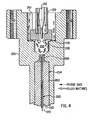
- An outlet end of a chromatographic column 270 is positioned in a liner 262 and the column/liner assembly is located in the central bore 263. Gas to be analyzed, such as the effluent (E) from the chromatographic column 270 is conducted within the column 270.
- Make-up fluid (M) is thereafter supplied into the central bore 263 and into a central bore of the liner 262 by a make-up gas feed 264.
- a fluid mixture (X) composed of a substantially uniform mixture of the make-up gas (M) and the column effluent (E) are then passed into the central bore 254 from an adapter cap 266.
- the fluid mixture (X) exits the cap 266 and immediately enters into the ionization chamber 256.
- the flow guide 220 is located at the uppermost portion of the ionization chamber 250 to effect an uppermost boundary to the active volume of the ionization chamber 256, the latter being defined as the region from which electrons are collected for measurement. Hence the active region is situated below the flow guide 220, thereby separating the anode 212 from the active volume.
- the flow guide 220 is made of a highly insulative material, such as a high purity alumina composition marketed as AL-300 and available from Wesgo/Duramic Precision Engineering Ceramics, Fairfield, N.J.
- the presence of the curved washer 230 and the flat sides 222 allow the passage of purge gas (P) that originates from the purge flow inlet 218 and travels through the central bores 214 and 226 so as to be redirected (illustrated as purge gas P) over the lower major surface 229 of the flow guide 220.
- purge gas P purge gas
- the lower major side 229 of the flow guide 220 faces into the ionization chamber 256 and thus towards the outlet end of the column/liner assembly.
- the ionization chamber 256 has a cup-shaped section with the radioactive source 258 on its side wall being so designed and positioned such that the fluid mixture (X) can pass upwardly into the ionization chamber 256 for subsequent ionization of the sample molecules that are present in the fluid mixture (X). Further flow of the fluid mixture (X) is partially constrained by the lower major surface 229 of the flow guide 222 and by a fluid barrier provided by the purge gas flow (P) from a central bore 226 in the flow guide 222. That is, the fluid mixture (X) is prevented from contacting the anode 212 and is made to exit the ionization chamber 256 along the flat portions 222 of the side wall of the flow guide 222.
- the anode 212 is not actively swept by the fluid mixture (X).
- the anode 212 is effectively separated by the flow guide 220 from the fluid mixture (X) and the potential for contamination of the anode 212 by compounds in the fluid mixture is greatly reduced.
- the desired mixing of the effluent and make-up gas is preferably implemented by a mixing device provided in the form of a hollow, tubular liner 500 formed of deactivated quartz and having a flow acceleration region 510 wherein the make-up gas and the effluent are subject to a momentary but substantial increase in velocity, thus causing turbulent flow within the flow acceleration region 510.
- the desired turbulent flow provides a substantially uniformly mixed product of the effluent (E) and the make-up gas (M).
- the flow acceleration region 510 is preferably provided by localized reduction of the internal diameter (I.D.) of the liner to a value that is approximately one-half to one-quarter of the average internal diameter. In one prototype of the liner 500, successful mixing was effected by a reduction of an average internal diameter of approximately 1000 micrometers to approximately 300 micrometers.
- FIG. 6 improved quantitative results are represented in a response curve obtained from the ECD 100 illustrated in Figured 1 (i.e., the ECD installed in the HP 5890 Gas Chromatograph) which was modified to include a sample inlet system having a prototype version of the illustrated liner 500.
- the illustrated response curve indicates the relationship between an injected sample amount and the resulting area count in the detector response.
- the detector response factor is considered to be the detector response per unit sample.
- the illustrated curves exhibit: (a) in the concentration mode of operation, the detector response factor follows a linear decrease in response to an increase in the flow rate of the fluid mixture (X); and (b) in the coulometric mode of operation, the detector response factor is generally independent of the flow rate of the fluid mixture (X).
Landscapes
- Physics & Mathematics (AREA)
- Health & Medical Sciences (AREA)
- Life Sciences & Earth Sciences (AREA)
- Chemical & Material Sciences (AREA)
- Analytical Chemistry (AREA)
- Biochemistry (AREA)
- General Health & Medical Sciences (AREA)
- General Physics & Mathematics (AREA)
- Immunology (AREA)
- Pathology (AREA)
- Other Investigation Or Analysis Of Materials By Electrical Means (AREA)
Applications Claiming Priority (2)
| Application Number | Priority Date | Filing Date | Title |
|---|---|---|---|
| US706900 | 1996-09-03 | ||
| US08/706,900 US5760291A (en) | 1996-09-03 | 1996-09-03 | Method and apparatus for mixing column effluent and make-up gas in an electron capture detector |
Publications (2)
| Publication Number | Publication Date |
|---|---|
| EP0831325A1 EP0831325A1 (en) | 1998-03-25 |
| EP0831325B1 true EP0831325B1 (en) | 2008-06-04 |
Family
ID=24839540
Family Applications (1)
| Application Number | Title | Priority Date | Filing Date |
|---|---|---|---|
| EP97112297A Expired - Lifetime EP0831325B1 (en) | 1996-09-03 | 1997-07-17 | Method and apparatus for ion discrimination in an electron capture detector |
Country Status (4)
| Country | Link |
|---|---|
| US (1) | US5760291A (2) |
| EP (1) | EP0831325B1 (2) |
| JP (1) | JP3907793B2 (2) |
| DE (1) | DE69738746D1 (2) |
Families Citing this family (5)
| Publication number | Priority date | Publication date | Assignee | Title |
|---|---|---|---|---|
| US5804828A (en) * | 1996-09-30 | 1998-09-08 | Hewlett-Packard Company | Method and apparatus for optimizing the sensitivity and linearity of an electron capture detector |
| GB0712362D0 (en) * | 2007-06-26 | 2007-08-01 | Smiths Group Plc | Detectors and nozzles |
| US8802581B2 (en) | 2009-08-21 | 2014-08-12 | Corning Incorporated | Zircon compatible glasses for down draw |
| US8713989B2 (en) | 2011-03-23 | 2014-05-06 | Agilent Technologies, Inc. | Restricted line of sight design for inlet liner |
| WO2014184947A1 (ja) * | 2013-05-17 | 2014-11-20 | 株式会社島津製作所 | 電子捕獲検出器 |
Family Cites Families (41)
| Publication number | Priority date | Publication date | Assignee | Title |
|---|---|---|---|---|
| US3009097A (en) * | 1958-02-19 | 1961-11-14 | Mine Safety Appliances Co | Method of oxygen detection |
| US3247375A (en) * | 1960-12-23 | 1966-04-19 | James E Lovelock | Gas analysis method and device for the qualitative and quantitative analysis of classes of organic vapors |
| US3378725A (en) * | 1964-04-15 | 1968-04-16 | Beckman Instruments Inc | Electron capture detector having separate ionization and sensing regions |
| US3444722A (en) * | 1966-09-09 | 1969-05-20 | Phillips Petroleum Co | Device for supplying carrier gas to transport eluted portion of sample and to backflush chromatographic column |
| US3566107A (en) * | 1967-11-24 | 1971-02-23 | Hewlett Packard Co | Nickel 63 electron capture detector |
| US3668382A (en) * | 1968-11-26 | 1972-06-06 | Franklin Gno Corp | Separation and detection of trace substances in gaseous samples containing moisture by diluting with dry air |
| US3634754A (en) * | 1969-06-23 | 1972-01-11 | Shell Oil Co | Method and apparatus for linearly measuring electron capture with an electron capture detector |
| CS154807B1 (2) * | 1972-05-15 | 1974-04-30 | ||
| GB1482611A (en) * | 1974-04-08 | 1977-08-10 | Lovelock J | Selective detection of a component in an atmosphere |
| US4031397A (en) * | 1975-08-25 | 1977-06-21 | Massachusetts Institute Of Technology | Method and apparatus for separating isotopes |
| US4063156A (en) * | 1976-02-27 | 1977-12-13 | Varian Associates, Inc. | Assymetric cylinder electron capture detector |
| DE2658371C2 (de) * | 1976-12-23 | 1983-03-03 | Carl Robert Eckelmann AG, 2000 Hamburg | Verfahren zum Pyrolysieren von Altreifen |
| GB1597622A (en) * | 1977-03-11 | 1981-09-09 | Lovelock J E | Solute switching systems incorporating corona discharge devices |
| EP0009787B2 (de) * | 1978-10-11 | 1986-07-09 | Bayer Ag | Verfahren zur Monohalogenierung von Alkylbenzolen in alpha-Stellung |
| US4264817A (en) * | 1979-02-27 | 1981-04-28 | Hewlett-Packard Company | Coaxial electron capture detector with thermionic emission electron source |
| US4304997A (en) * | 1979-02-27 | 1981-12-08 | Hewlett-Packard Company | Electron capture detector with thermionic emission electron source |
| US4261964A (en) * | 1979-07-16 | 1981-04-14 | J. M. Huber Corporation | Utilization of combustible components of a tail-gas in the manufacture of carbon black at a high production rate |
| US4308242A (en) * | 1980-01-24 | 1981-12-29 | Phillips Petroleum Company | Producing sulfur-containing compositions from gaseous sulfur compounds |
| IT1134198B (it) * | 1980-11-06 | 1986-07-31 | Erba Strumentazione | Dispositivo per l'iniezione a vaporizzazione in una colonna gas-cromatografica |
| US4388411A (en) * | 1981-04-29 | 1983-06-14 | Hewlett-Packard Company | Apparatus and method for detecting fluid |
| US4517394A (en) * | 1983-07-05 | 1985-05-14 | W. R. Grace & Co. | Preparation of nitro compounds by vapor phase nitration of carboxylic acids |
| GB2147734B (en) * | 1983-08-11 | 1987-03-04 | Varian Associates | Flow contoured electron capture detector cell |
| US4684807A (en) * | 1983-08-11 | 1987-08-04 | Varian Associates, Inc. | Flow contoured electron capture detector cell |
| US4651008A (en) * | 1983-08-11 | 1987-03-17 | Varian Associates, Inc. | Sample inlet system for an electron capture detector |
| US4670220A (en) * | 1984-03-07 | 1987-06-02 | Varian Associates, Inc. | Sample valve for solute modulated synchronous detection |
| GB8431663D0 (en) * | 1984-12-14 | 1985-01-30 | Perkin Elmer Corp | Ionization detector |
| GB8506788D0 (en) * | 1985-03-15 | 1985-04-17 | Secr Defence | Thermal electron source |
| SU1693536A1 (ru) * | 1985-06-11 | 1991-11-23 | Специализированное конструкторско-технологическое бюро с опытным производством Института электроники им.У.А.Арифова | Поверхностно-ионизационный детектор органических соединений |
| US4851683A (en) * | 1987-03-09 | 1989-07-25 | Brigham Young University | Element specific radio frequency discharge helium plasma detector for chromatography |
| US4887464A (en) * | 1988-11-22 | 1989-12-19 | Anadrill, Inc. | Measurement system and method for quantitatively determining the concentrations of a plurality of gases in drilling mud |
| US4994096A (en) * | 1989-05-09 | 1991-02-19 | Hewlett-Packard Co. | Gas chromatograph having integrated pressure programmer |
| US4995222A (en) * | 1990-01-08 | 1991-02-26 | The Upjohn Company | Ampoule sealing apparatus |
| US5302325A (en) * | 1990-09-25 | 1994-04-12 | Praxair Technology, Inc. | In-line dispersion of gas in liquid |
| US5108466A (en) * | 1990-12-21 | 1992-04-28 | Hewlett-Packard Company | Apparatus and methods for controlling fluids provided to a chromatographic detector |
| US5153519A (en) * | 1991-02-28 | 1992-10-06 | Wentworth Wayne E | High voltage spark excitation and ionization detector system |
| US5281397A (en) * | 1991-03-14 | 1994-01-25 | General Electric Company | Adjustable open-split interface for a gas chromatograph and a mass spectrometer |
| US5108468A (en) * | 1991-03-26 | 1992-04-28 | General Electric Company | Switching system for a multidimensional gas chromatograph |
| DE69329061T2 (de) * | 1992-05-14 | 2000-12-21 | Idec Izumi Corp., Osaka | Vorrichtung zur lösung eines gases in bzw zur mischung einer flüssigkeit |
| GB9309720D0 (en) * | 1993-05-12 | 1993-06-23 | British Nuclear Fuels Plc | Measuring fluid flow rate |
| US5472645A (en) * | 1994-11-23 | 1995-12-05 | Cyclone Technologies, Inc. | Cyclone vortex system and process |
| US5479022A (en) * | 1994-06-17 | 1995-12-26 | Varian Associates, Inc. | Electron capture detector with guard electrode |
-
1996
- 1996-09-03 US US08/706,900 patent/US5760291A/en not_active Expired - Lifetime
-
1997
- 1997-07-17 EP EP97112297A patent/EP0831325B1/en not_active Expired - Lifetime
- 1997-07-17 DE DE69738746T patent/DE69738746D1/de not_active Expired - Lifetime
- 1997-08-22 JP JP22621197A patent/JP3907793B2/ja not_active Expired - Fee Related
Also Published As
| Publication number | Publication date |
|---|---|
| JP3907793B2 (ja) | 2007-04-18 |
| EP0831325A1 (en) | 1998-03-25 |
| JPH10197485A (ja) | 1998-07-31 |
| US5760291A (en) | 1998-06-02 |
| DE69738746D1 (de) | 2008-07-17 |
Similar Documents
| Publication | Publication Date | Title |
|---|---|---|
| US5218203A (en) | Ion source and sample introduction method and apparatus using two stage ionization for producing sample gas ions | |
| US5889404A (en) | Discharge ionization detector having efficient transfer of metastables for ionization of sample molecules | |
| US6410915B1 (en) | Multi-inlet mass spectrometer for analysis of liquid samples by electrospray or atmospheric pressure ionization | |
| US4378499A (en) | Chemical conversion for ion mobility detectors using surface interactions | |
| CA2653623C (en) | Miniaturized ion mobility spectrometer | |
| JP2000504111A (ja) | 分析測定器のためのコロナ放電イオン源 | |
| US5014009A (en) | Detector for gas chromatograph for detecting ammonia and amine compounds | |
| US4304997A (en) | Electron capture detector with thermionic emission electron source | |
| US5739699A (en) | Method and apparatus for ion discrimination in an electron capture detector | |
| US4740695A (en) | Ionization detectors for gas chromatography | |
| EP0831325B1 (en) | Method and apparatus for ion discrimination in an electron capture detector | |
| EP1279955B2 (en) | Helium ionization detector | |
| US6037179A (en) | Method and apparatus for suppression of analyte diffusion in an ionization detector | |
| US4264817A (en) | Coaxial electron capture detector with thermionic emission electron source | |
| US5920072A (en) | Ionization detector | |
| US5948141A (en) | Method and apparatus for purification of a discharge gas | |
| US6107805A (en) | Extended detection zone in an ionization detector | |
| CN112649494A (zh) | 一种基于光电离离子迁移谱的多峰定量方法 | |
| CA2314135A1 (en) | Transport detector with oxide surface coating | |
| US4684807A (en) | Flow contoured electron capture detector cell | |
| Václav et al. | Capillary electrophoresis device with double UV detection and its application to the determination of effective mobilities of peptides | |
| CN119495551B (zh) | 一种控制脉冲性漂气来提高离子迁移谱峰高的方法 | |
| EP0833152A1 (en) | Method and apparatus for optimizing the sensitivity and linearity of an electron capture detector | |
| JP5946111B2 (ja) | プラズマを用いた検出方法および検出装置 | |
| JPH0453256B2 (2) |
Legal Events
| Date | Code | Title | Description |
|---|---|---|---|
| PUAI | Public reference made under article 153(3) epc to a published international application that has entered the european phase |
Free format text: ORIGINAL CODE: 0009012 |
|
| AK | Designated contracting states |
Kind code of ref document: A1 Designated state(s): DE FR GB |
|
| AX | Request for extension of the european patent |
Free format text: AL;LT;LV;RO;SI |
|
| 17P | Request for examination filed |
Effective date: 19980414 |
|
| AKX | Designation fees paid |
Free format text: DE FR GB |
|
| RBV | Designated contracting states (corrected) |
Designated state(s): DE FR GB |
|
| RAP1 | Party data changed (applicant data changed or rights of an application transferred) |
Owner name: HEWLETT-PACKARD COMPANY, A DELAWARE CORPORATION |
|
| RAP1 | Party data changed (applicant data changed or rights of an application transferred) |
Owner name: AGILENT TECHNOLOGIES, INC. |
|
| RAP1 | Party data changed (applicant data changed or rights of an application transferred) |
Owner name: AGILENT TECHNOLOGIES INC. |
|
| RAP1 | Party data changed (applicant data changed or rights of an application transferred) |
Owner name: AGILENT TECHNOLOGIES INC. A DELAWARE CORPORATION |
|
| RAP1 | Party data changed (applicant data changed or rights of an application transferred) |
Owner name: AGILENT TECHNOLOGIES, INC. (A DELAWARE CORPORATION |
|
| 17Q | First examination report despatched |
Effective date: 20040408 |
|
| RAP1 | Party data changed (applicant data changed or rights of an application transferred) |
Owner name: AGILENT TECHNOLOGIES, INC. |
|
| GRAP | Despatch of communication of intention to grant a patent |
Free format text: ORIGINAL CODE: EPIDOSNIGR1 |
|
| GRAS | Grant fee paid |
Free format text: ORIGINAL CODE: EPIDOSNIGR3 |
|
| GRAA | (expected) grant |
Free format text: ORIGINAL CODE: 0009210 |
|
| AK | Designated contracting states |
Kind code of ref document: B1 Designated state(s): DE FR GB |
|
| REG | Reference to a national code |
Ref country code: GB Ref legal event code: FG4D |
|
| REF | Corresponds to: |
Ref document number: 69738746 Country of ref document: DE Date of ref document: 20080717 Kind code of ref document: P |
|
| PLBE | No opposition filed within time limit |
Free format text: ORIGINAL CODE: 0009261 |
|
| STAA | Information on the status of an ep patent application or granted ep patent |
Free format text: STATUS: NO OPPOSITION FILED WITHIN TIME LIMIT |
|
| 26N | No opposition filed |
Effective date: 20090305 |
|
| REG | Reference to a national code |
Ref country code: FR Ref legal event code: ST Effective date: 20090529 |
|
| PG25 | Lapsed in a contracting state [announced via postgrant information from national office to epo] |
Ref country code: FR Free format text: LAPSE BECAUSE OF NON-PAYMENT OF DUE FEES Effective date: 20080731 |
|
| PGFP | Annual fee paid to national office [announced via postgrant information from national office to epo] |
Ref country code: GB Payment date: 20160713 Year of fee payment: 20 Ref country code: DE Payment date: 20160712 Year of fee payment: 20 |
|
| REG | Reference to a national code |
Ref country code: DE Ref legal event code: R071 Ref document number: 69738746 Country of ref document: DE |
|
| REG | Reference to a national code |
Ref country code: GB Ref legal event code: PE20 Expiry date: 20170716 |
|
| PG25 | Lapsed in a contracting state [announced via postgrant information from national office to epo] |
Ref country code: GB Free format text: LAPSE BECAUSE OF EXPIRATION OF PROTECTION Effective date: 20170716 |