EP0831423B1 - Rendu d'image basé sur un espace lumineux - Google Patents
Rendu d'image basé sur un espace lumineux Download PDFInfo
- Publication number
- EP0831423B1 EP0831423B1 EP97307227A EP97307227A EP0831423B1 EP 0831423 B1 EP0831423 B1 EP 0831423B1 EP 97307227 A EP97307227 A EP 97307227A EP 97307227 A EP97307227 A EP 97307227A EP 0831423 B1 EP0831423 B1 EP 0831423B1
- Authority
- EP
- European Patent Office
- Prior art keywords
- image
- ray
- reference plane
- light
- visual point
- Prior art date
- Legal status (The legal status is an assumption and is not a legal conclusion. Google has not performed a legal analysis and makes no representation as to the accuracy of the status listed.)
- Expired - Lifetime
Links
Images


Classifications
-
- G—PHYSICS
- G06—COMPUTING OR CALCULATING; COUNTING
- G06T—IMAGE DATA PROCESSING OR GENERATION, IN GENERAL
- G06T15/00—Three-dimensional [3D] image rendering
- G06T15/10—Geometric effects
- G06T15/20—Perspective computation
- G06T15/205—Image-based rendering
Definitions
- the present invention relates to image processing for forming an image at an arbitrary visual point position by using images obtained by photographing an object at different visual point positions.
- a light is emitted by a light source or a reflection light of an object.
- the light crossing a certain point in the three-dimensional space is unconditionally determined by five variables indicative of its position (x, y, z) and direction ( ⁇ , ⁇ ).
- a function showing a light intensity of the light is defined as f
- light group data in the three-dimensional space is expressed by f(x, y, z, ⁇ , ⁇ ).
- the light group data is expressed by f(x, y, z, ⁇ , ⁇ ; t) and the light group in the three-dimensional space is described as a six-dimensional space.
- This space is called a light space. Since the normal two-dimensional image is considered as an image obtained by recording a light group gathering at a single visual point, it is possible to consider that the two-dimensional image is an image obtained by recording two-dimensional data of f ( ⁇ , ⁇ )
- the plane is called a reference plane.
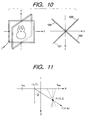
- a real space is as shown in Fig. 11.
- the light group emitted from the reference plane is described as f(x, ⁇ ) by using two variables of a position x and an angle ⁇ . Therefore, with respect to the light group which passes a certain point (X, Z) in the real space, a relation expressed by the following equation is satisfied.
- the discreted light space data includes data in which no value exists (undefined)
- the discreted light space data includes data in which no value exists (undefined)
- a desired image cannot be generated.
- a method whereby the nearest data having a value is obtained and such an undefined value is substituted by this data is also considered.
- this method is used, however, there is a problem such that it takes a surplus time to generate the arbitrary visual point image.
- Light Field Rendering by Levoy and Hanrahan in Computer Graphics Proceedings, Annual Conference Series, 1996, pages 31-42 discloses a method for generating new views from arbitrary camera positions without depth information or feature matching, simply by combining and resampling the available images.
- the key to this technique lies in interpreting the input images as 2D slices of a 4D function - the light field. This function completely characterizes the flow of light through unobstructed space in a static scene with fixed illumination.
- the Lumigraph by Gortler et al in Computer Graphics Proceedings, Annual Conference Series, 1996, pages 43-54 discloses a method for capturing the complete appearance of both synthetic and real world objects and scenes, representing this information, and then using this representation to render images of the object from new camera positions.
- the approach does not rely on geometric representations. Instead a 4D function called a Lumigraph is sampled and reconstructed.
- the Lumigraph is a subset of the complete plenoptic function that describes the flow of light at all positions in all directions. With the Lumigraph, new images of the object can be generated very quickly, independent of the geometric or illumination complexity of the scene or object.
- the present invention also provides an image processing apparatus as set out in claim 10.
- the present invention further provides a computer program product as set out in claim 19.
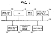
- Fig. 1 shows a schematic diagram of an embodiment of an apparatus for generating and displaying an image at an arbitrary visual point position from an actual photographed image group photographed at a plurality of visual point positions.
- reference numeral 101 denotes an image input apparatus for photographing an actual photographed image group.
- the image input apparatus a number of images can be photographed by deviating one camera or by setting a plurality of cameras.
- a database in which a number of photographed images have previously been stored can be also used.
- Reference numeral 102 denotes a CPU for performing processes in accordance with a processing procedure stored in a memory device 103; 103 the memory device in which image data of the actual photographed image group, light space data formed from a multi-visual point image, a program showing the processing procedure of the CPU, and the like are stored and a part of which is used as a work memory; and 104 a visual point and line of sight detector for detecting a visual point position and a direction of a line of sight of the observer.
- a visual point and line of sight detector an input device such as keyboard, mouse, or the like can be used or a device such as an HMD (head mount display) having a sensor or the like can be used.
- Reference numeral 105 denotes an image output apparatus for displaying an image generated in accordance with the visual point position and direction of the line of sight of the observer.
- an image output apparatus a general two-dimensional display such as CRT, liquid crystal, or the like can be used or a three-dimensional display such as lenticular, HMD, or the like can be also used.
- a program it is sufficient that the program is recorded in a storage medium such as FD (floppy disk), CD-ROM, magnetic tape, or the like and is read out by a storage medium reader 106 and is stored to the memory device 103.
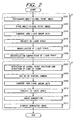
- a frame (A) in Fig. 2 denotes a portion in a range from the photographing of multi-visual point images to the formation of a light space and the processes are performed in an off-line manner.
- a frame (B) in Fig. 2 denotes a portion where the image at an arbitrary visual point position is generated from the light space and is displayed and the processes are performed in an on-line manner.
- step S201 (E) images are photographed at a plurality of visual point positions by using the image input apparatus 101 and are stored into the memory device 103 in step S202.
- step S203 the data of one line at the head in each image data stored in the memory device 103 is decomposed into a light group and the light group is projected to the light space in accordance with the equations (1) and (2).
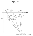
- Fig. 3 shows a situation in which an image is photographed by setting a camera at a position where a deviation angle of an optic axis for the Z axis is equal to ⁇ and the position of the center of lens is equal to Q (x0, z0) (this position is referred to as a visual point position).
- reference numeral 301 denotes a visual point position Q (x0, z0); 302 a photographed plane; 303 a j-th picture element on an arbitrary line in the photographed plane; 304 an X axis; 305 a Z axis; 306 an angle ⁇ formed between the optic axis and the Z axis; 307 an angle ⁇ formed between the Z axis and a light passing the visual point position 301 and picture element 303; 308 an angle ⁇ of view of the camera; and 309 a point at which the light passing the j-th picture element intersects the X axis.
- the directions of lights of data (as many as (E ⁇ m) picture elements) of one line at the head in each image data stored in the memory device 103 are obtained, respectively (step S203).
- Such a light group is projected to the light space in accordance with the equations (1) and (2) (step S204).
- step S205 further, an (x) axis and a (u) axis of the projected light space data are quantized so as to keep a resolution similar to that of the input image. By quantizing in such a manner, a generation of vain data can be suppressed.
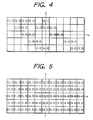
- Fig. 4 shows an example of quantized light space data at a time point when the processes up to step S205 are finished.
- the x axis and u axis are quantized and there are (11 ⁇ 5) elements.
- a set of [image number, picture element number] corresponding to each light is recorded in each element.
- the values of the elements whose values are undefined are presumed.
- a nearest neighbor method is now used as a presuming method, the invention is not limited to this method and they can be also presumed by using any method.
- the presumed values are recorded in the corresponding element as a set of [image number, picture element number].
- a visual point position of an image to be generated for example, a position, a direction of a line of sight, and the like of the observer are inputted.
- a magnetic sensor for example, a magnetic sensor, a line of sight detector, or the like.
- any means can be used so long as the above object is accomplished.
- a virtual camera is set in the inputted visual point position and direction of the line of sight.
- each picture element of the head line of the virtual camera image is decomposed to a light group.
- step S210 to which position in the light space each light of the light group obtained in step S209 is projected is obtained by using the equations (1) and (2). At this time, the data is quantized in a manner similar to the process in step S205. In step S211, an image is generated by reading the element at the position projected in step S210 from the light space. This process will now be described in detail with reference to Fig. 5.
- Fig. 5 is a correspondence relation table obtained by projecting the input image into the light space and performing the quantizing and interpolating processes.
- Numerical values written in each element are a set of [input image number, picture element number in the main scanning direction].
- the positions in the x and u directions of each element are given as shown in the diagram. For instance, the values of element (0, 0) are equal to [2, 3] and the values of element (1, 2) are equal to [3, 2].
- step S210 now assuming that the light beams (five light beams in this case) are projected to the positions of elements (-2, 2), (-1, 1), (0, 0), (1, -1), and (2, -2) in the light space, the values recorded in those elements, namely, [5, 1], [2, 2], [2, 3], [4, 5], and [3, 4] are read out.
- step S211 an image is reconstructed by using the readout values.
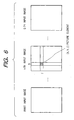
- a picture element existing at the position of the h picture element in the main scanning direction in the k-th image and the j picture element in the sub scanning direction is expressed as ⁇ k, h, j ⁇ (refer to Fig. 6).
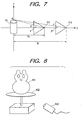
- Fig. 7 is a diagram showing a principle for correcting the distortion of the reconstructed image.
- reference numeral 701 denotes an object to be photographed; 702 an image at a visual point position P to be reconstructed; and 703 an input image at a visual point position S.
- the value of the m'-th scan line of the image 702 at the visual point position P to be reconstructed is equal to the value of the n'-th scan line which is given by the equation (7) of the image 703 at the visual point position S. Therefore, it is sufficient to give the same picture element values as ⁇ 5, 1, R_5_1 ⁇ for the (1, 1) picture element of the reconstructed image, ⁇ 2, 2, R_2_1 ⁇ for the (2, 1) picture element, ..., and ⁇ 3, 4, R_3_1 ⁇ for the (5, 1) picture element.
- R_i_j denotes a value which is calculated by the equation (7) from the i-th input image position, the reconstructed image position, and the line position to be obtained in the reconstructed image.
- the reconstructed image can be generated by obtaining the picture element values as mentioned above with respect to all of the picture elements.
- n' which is given by the equation (7) satisfies the relation (n' ⁇ 0) or (n' > n)
- predetermined picture element values are used.
- the position where the input image is projected to the light space is preliminarily calculated and held in a table format (correspondence relation table).
- a table format correspondence relation table.
- a construction of an image processing apparatus of the second embodiment is similar to Fig. 1.
- Fig. 8 is an explanatory diagram of a method of obtaining multi-visual point images in the image input apparatus 101 of the image processing apparatus of the second embodiment.
- reference numeral 801 denotes an object which is used for photographing; 802 a rotational table which rotates with the object 801 thereon in order to photograph the object 801 from the positions around it; and 803 a CCD camera which is used to photograph the object 801.
- the object 801 is put on the rotational table 802 and multi-visual point images are photographed by the CCD camera 803 while rotating the table 802.
- the multi-visual point images photographed by the CCD camera 803 are stored into the memory device 103.
- Fig. 9 is a flowchart showing a flow of processes of the image processing apparatus of the second embodiment.
- multi-visual point images are obtained from the image input apparatus 101 in step S901 and are stored in the memory device 103 in step S902.
- the number of reference planes of the light space and their arrangement are determined in step S903.
- predetermined values can be used or a method whereby the operator inputs them from a data input device (not shown) at the time of starting the processes can be also used.
- reference planes of the number according to such a limited plane can be also set.
- the invention is not limited to the above value.
- the reference planes are radially arranged so that the u axes of four reference planes are overlapped and the reference planes are deviated every 90° around the u axis as a center.
- Fig. 10 This state is shown in Fig. 10.
- the number of reference planes is not limited to four but any number of reference planes can be used.
- the reference planes are arranged at regular intervals of every 90° in this example, it is not always necessary to arrange them at regular intervals.
- a construction such that they are radially arranged denotes that all of the reference planes are crossed on one straight line (rotary axis at the time of photographing the object. In this case, this straight line is set to the Y axis.) passing the object and all of the angles formed by the adjacent reference planes are equal and an angle between one of the reference planes and the Z axis is equal to ⁇ /2 (where, ⁇ denotes an angle between the neighboring reference planes).
- reference numeral 1001 denotes a reference plane 1 corresponding to the light space to record a locus of the light which arrives from the object 801 and whose angle lies within a range of (0° ⁇ ⁇ ⁇ 90°); 1002 a reference plane 2 corresponding to the light space to record a locus of the light which arrives from the object 801 and whose angle lies within a range of (90° ⁇ ⁇ ⁇ 180°); 1003 a reference plane 3 corresponding to the light space to record a locus of the light which arrives from the object 801 and whose angle lies within a range of (180° ⁇ ⁇ ⁇ 270°); and 1004 a reference plane 4 corresponding to the light space to record a locus of the light which arrives from the object 801 and whose angle lies within a range of (270° ⁇ ⁇ ⁇ 360°).
- step S904 in a manner similar to step S203, the data of one line at the head in each image data stored in the memory device 103 is decomposed to a light group and to which one of the four reference planes each light is recorded is determined by a value in the direction ⁇ of each light derived.
- step S905 [image number, picture element number] of this light is recorded at the position which is given by the equations (1) and (2) on the x-u space corresponding to the reference plane.
- the equations (1) and (2) can be applied.
- the angle of rotation and the angle to be subtracted are obtained by (c1 + c2)/2 when c1 ⁇ ⁇ ⁇ c2.
- the above processes are executed to the light passing all of the picture elements of (0 ⁇ j ⁇ N) and image numbers of the multi-visual point images corresponding to the corresponding x-u space and picture element positions (picture element numbers) in the first line of the images are recorded. Further, the above processes are repetitively executed to all of the inputted multi-visual point images. All of the light beams obtained from the inputted multi-visual point images are recorded into the four x-u spaces by the above processes. Now, the processes are performed to only the first line of the multi-visual point images and no process is performed to the remaining lines.
- step S906 Undefined picture element values on the light space are presumed in step S907 and presumed results are recorded as a set of [image number, picture element number] to the corresponding element in the light space. Since processes in steps S906 and S907 are similar to the processes performed in the first embodiment, their descriptions are omitted here.
- a visual point position and a direction of a line of sight of the observer are subsequently detected in step S908.
- the visual point position of the observer is detected here, an arbitrary position can be also inputted and the invention is not limited to the above method.
- an image which can be seen by the observer is equivalent to an image photographed by a virtual camera in which the position of the lens center of the camera is equal to (x, z) and the optic axial direction is set to ⁇ and the angle of view is set to ⁇ .
- step S909 the virtual camera is set at the visual point position and in the line of sight direction which were detected.
- step S910 each picture element of the head line of the image of the virtual camera is decomposed into a light group.
- step S911 at which position in the x-u space the light group is projected is calculated. Calculating equations in this instance are the same as the equations (1) and (2). Thus, since the image number and picture element number recorded at the corresponding positions on the x-u space can be known, the line number is subsequently calculated. A calculation of the line number can be performed in a manner similar to the case of the first embodiment by using the equation (7). When the line number is obtained, since the picture element in the input image group is unconditionally determined, the color of the picture element is given to picture elements of the virtual camera image corresponding to the foregoing light.
- step S912 By executing the above processes with respect to all of the picture elements of the virtual camera image, in step S912, an image corresponding to the visual point position and the direction of the line of sight of the observer can be generated. In step S913, the image generated in step S912 can be also displayed.
- any apparatus can be used so long as it can detect the visual point position and the direction of the line of sight.
- a stereoscopic display unit such as a lenticular system, glasses system, or the like which can stereoscopically observe with both eyes is used and the images corresponding to the positions of the right and left eyes of the observers are generated in step S211 or S912, so that a both-eye stereoscopic display apparatus which can cope with the movement of the visual point of the observer is derived.
- Embodiments of the invention may comprise a system comprising a plurality of equipment or an apparatus comprising one equipment. It will be obviously understood that an embodiment may be attained by supplying a program to a system or an apparatus. In this case, the program is stored into a storage medium that is installed in the system or apparatus and the program is read out from the storage medium to the system or apparatus, so that the system or apparatus operates in accordance with a predetermined method.
Landscapes
- Engineering & Computer Science (AREA)
- Theoretical Computer Science (AREA)
- Physics & Mathematics (AREA)
- Computing Systems (AREA)
- Geometry (AREA)
- Computer Graphics (AREA)
- General Physics & Mathematics (AREA)
- Image Processing (AREA)
- Image Analysis (AREA)
- Processing Or Creating Images (AREA)
Claims (19)
- Procédé de traitement d'images, comprenant :une étape d'entrée d'images (S202, S902) consistant à fournir en entrée une pluralité d'images photographiées en une pluralité de positions de points visuels ;(a) la projection (S203, S904) de rayons lumineux théoriques respectifs passant par des pixels de chaque image d'entrée pour définir des rayons respectifs dans un plan de référence bidimensionnel prédéterminé (X-Z) au sein d'un espace tridimensionnel (X-Y-Z) ;
caractérisé par :(b) la détermination (S204 ; S905) de la direction respective (θ) formée par chaque rayon avec un axe prédéterminé du système de coordonnées du plan de référence et un point respectif pour chaque rayon comprenant un point sur un axe prédéterminé du système de coordonnées du plan de référence par lequel passe le rayon ;(c) une étape de production d'une relation de correspondance (S204 ; S905) consistant à produire une table de relations de correspondance définissant une relation entre des pixels d'images dans les images d'entrée et des positions dans un espace de lumière, l'espace de lumière comprenant un espace bidimensionnel défini par un système de coordonnées bidimensionnel ayant un premier axe le long duquel les valeurs varient en fonction de la direction (θ) formée entre le rayon et l'axe prédéterminé du plan de référence, et un second axe le long duquel les valeurs varient en fonction de la valeur de la coordonnée du point d'intersection entre le rayon et l'axe prédéterminé du plan de référence, l'espace bidimensionnel de l'espace de lumière étant divisé en une pluralité d'éléments, et la table de relations de correspondance étant produite en :définissant un élément respectif pour chaque rayon dans l'espace de lumière comprenant l'élément défini par les coordonnées calculées pour le rayon ayant la direction déterminée et le point d'intersection avec l'axe prédéterminé du plan de référence ; etstockant des données pour chaque élément dans l'espace de lumière défini pour un rayon, les données stockées définissant l'image d'entrée et le pixel de celle-ci d'où provient le rayon ;(d) une étape de production d'image (S208 ; S209, S210, S211 ; S909, S910, S911, S912) consistant à produire une image à une position arbitraire d'un point visuel sur la base de la relation de correspondance stockée dans la table de relations de correspondance ; et(e) une étape d'affichage d'image (S212 ; S913) consistant à afficher l'image produite lors de ladite étape de production. - Procédé selon la revendication 1, dans lequel, lors de ladite étape d'entrée d'image, des images sont photographiées depuis un ensemble de directions circonférentielles d'un objet tout en plaçant l'objet sur une table tournante et en faisant tourner ladite table tournante.
- Procédé selon la revendication 1, dans lequel, lors de ladite étape de projection, des rayons lumineux théoriques sont projetés de façon à passer par chaque pixel de la première ligne de chaque image d'entrée.
- Procédé selon la revendication 1, dans lequel ladite étape de production d'image comprend une étape de correction pour corriger une déformation de l'image produite en corrigeant une parallaxe verticale entre ladite position arbitraire d'un point visuel et une position d'un point visuel de ladite pluralité de positions de points visuels.
- Procédé selon la revendication 4, dans lequel, lors de ladite étape de correction, la parallaxe verticale desdites deux positions de points visuels correspondant à un point arbitraire de l'objet devant être photographié est corrigée en utilisant des lignes de balayage provenant desdites deux positions de points visuels.
- Procédé selon la revendication 1, comportant en outre :une étape de réglage consistant à régler une pluralité de plans de référence ; etune étape d'expression consistant à exprimer ledit plan de référence bidimensionnel prédéterminé (X-Z) sur la base de ladite pluralité de plans de référence réglés.
- Procédé selon la revendication 6, dans lequel ladite étape d'expression comprend une étape de quantification du plan de référence bidimensionnel prédéterminé en enregistrant un rayon passant par un pixel formant avec le plan de référence un angle le plus proche d'un angle droit.
- Procédé selon la revendication 1, dans lequel ladite position arbitraire du point visuel est obtenue par un capteur de position.
- Procédé selon l'une quelconque des revendications précédentes, dans lequel le traitement destiné à produire l'image à la position arbitraire d'un point visuel comprend :la projection (S209, S910) d'un rayon lumineux théorique respectif passant par chacun d'au moins certains pixels de l'image devant être produite, pour définir un rayon respectif dans le plan de référence prédéterminé (X-Y) au sein de l'espace tridimensionnel (X-Y-Z) ;la détermination (S210 ; S911) de l'angle respectif que forme chaque rayon avec l'axe prédéterminé du plan de référence et un point respectif pour chaque rayon comprenant un point sur l'axe prédéterminé du plan de référence par lequel passe le rayon ;la définition (S210 ; S911) d'un élément respectif pour chaque rayon de l'espace de lumière comprenant l'élément défini par les coordonnées de l'angle déterminé (θ) et le point d'intersection avec l'axe prédéterminé ;la lecture (S211 ; S912) de données depuis la table de relations de correspondance pour les éléments définis dans l'espace de lumière définissant des pixels d'images d'entrée ; etla production (S211, S912) de données d'images en utilisant les valeurs des pixels provenant des images d'entrée définies par les données lues depuis la table de relations de correspondance.
- Appareil de traitement d'images, comprenant :un moyen d'entrée d'images (101) pour fournir en entrée une pluralité d'images photographiées en une pluralité de positions de points visuels ;(a) un moyen de projection (102, 103) pour projeter des rayons lumineux théoriques respectifs passant par des pixels dans chaque image d'entrée pour définir des rayons respectifs dans un plan de référence bidimensionnel prédéterminé (X-Z) au sein d'un espace tridimensionnel (X-Y-Z) ;
caractérisé par :(b) un moyen de détermination (102, 103) pour déterminer (S204 ; S905) la direction respective (θ) formée par chaque rayon avec un axe prédéterminé du système de coordonnées du plan de référence et un point respectif pour chaque rayon comprenant un point sur un axe prédéterminé du système de coordonnées du plan de référence par lequel passe le rayon ;(c) un moyen de production de relations de correspondance (102, 103) pour produire une table de relations de correspondance définissant une relation entre des pixels d'images dans les images d'entrée et des positions dans un espace de lumière, l'espace de lumière comprenant un espace bidimensionnel défini par un système de coordonnées bidimensionnel ayant un premier axe le long duquel les valeurs varient en fonction de la direction (θ) formée entre le rayon et l'axe prédéterminé du plan de référence, et un second axe le long duquel les valeurs varient en fonction de la valeur de la coordonnée du point d'intersection entre le rayon et l'axe prédéterminé du plan de référence, l'espace bidimensionnel de l'espace de lumière étant divisé en une pluralité d'éléments, et le moyen de production de relations de correspondance ayant pour fonction de produire la table de relations de correspondance en :définissant un élément respectif pour chaque rayon de l'espace de lumière comprenant l'élément défini par les coordonnées calculées pour le rayon ayant la direction déterminée et le point d'intersection avec l'axe prédéterminé du plan de référence ; etstockant des données pour chaque élément dans l'espace de lumière défini pour un rayon, les données stockées définissant l'image d'entrée et le pixel de celle-ci d'où provient le rayon ;(d) un moyen de production d'image (102, 103) pour produire une image à une position arbitraire d'un point visuel sur la base de la relation de correspondance stockée dans ladite table de relations de correspondance ; et(e) un moyen d'affichage d'image (105) pour afficher l'image produite. - Appareil selon la revendication 10, dans lequel ledit moyen d'entrée d'images comprend un moyen (803) pour enregistrer des images d'un objet et une table tournante (802) sur laquelle l'objet peut être placé pour rotation.
- Appareil selon la revendication 10, dans lequel ledit moyen de projection a pour fonction de projeter des rayons lumineux théoriques passant par chaque pixel de la première ligne de chaque image d'entrée.
- Appareil selon la revendication 10, dans lequel ledit moyen de production d'image comporte un moyen de correction pour corriger une déformation de l'image produite en corrigeant une parallaxe verticale entre ladite position arbitraire d'un point visuel et la position d'un point visuel de ladite pluralité de positions de points visuels.
- Appareil selon la revendication 13, dans lequel ledit moyen de correction a pour fonction de corriger la parallaxe verticale desdites deux positions de points visuels correspondant à un point arbitraire sur l'objet devant être photographié en utilisant des lignes de balayage provenant desdites deux positions de points visuels.
- Appareil selon la revendication 10, comportant en outre :un moyen de réglage pour régler une pluralité de plans de référence ; etun moyen d'expression pour exprimer ledit plan de référence bidimensionnel prédéterminé (X-Z) sur la base de ladite pluralité de plans de référence réglés.
- Appareil selon la revendication 15, dans lequel ledit moyen d'expression comporte un moyen pour quantifier le plan de référence bidimensionnel prédéterminé en enregistrant un rayon passant par un pixel formant avec le plan de référence un angle le plus proche d'un angle droit.
- Appareil selon la revendication 10, comprenant en outre un capteur de position (104) ayant pour fonction d'obtenir ladite position arbitraire du point visuel.
- Appareil selon l'une quelconque des revendications 10 à 17, dans lequel le moyen de production d'image a pour fonction de produire l'image à la position arbitraire du point visuel en :projetant (S209, S910) un rayon lumineux théorique respectif passant par chacun d'au moins certains pixels de l'image devant être produite, pour définir un rayon respectif dans le plan de référence prédéterminé (X-Y) au sein de l'espace tridimensionnel (X-Y-Z) ;déterminant (S210, S911) l'angle respectif que forme chaque rayon avec l'axe prédéterminé du plan de référence et un point respectif pour chaque rayon comprenant un point sur l'axe prédéterminé du plan de référence par lequel passe le rayon ;définissant (S210, S911) un élément respectif pour chaque rayon de l'espace de lumière comprenant l'élément défini par les coordonnées de l'angle déterminé (θ) et le point d'intersection avec l'axe prédéterminé ;lisant (S211, S912) des données depuis la table de relations de correspondance pour les éléments définis dans l'espace de lumière définissant des pixels d'images d'entrée ; etproduisant (S211, S912) des données d'images en utilisant les valeurs des pixels provenant des images d'entrée définies par les données lues depuis la table de relations de correspondance.
- Produit à base de programme informatique comprenant un support portant un programme informatique pour programmer un appareil de traitement programmable afin qu'il devienne capable de mettre en oeuvre un procédé selon au moins l'une des revendications 1 à 9.
Applications Claiming Priority (3)
| Application Number | Priority Date | Filing Date | Title |
|---|---|---|---|
| JP249974/96 | 1996-09-20 | ||
| JP24997496 | 1996-09-20 | ||
| JP8249974A JPH1097642A (ja) | 1996-09-20 | 1996-09-20 | 画像処理方法及び装置及び記憶媒体 |
Publications (3)
| Publication Number | Publication Date |
|---|---|
| EP0831423A2 EP0831423A2 (fr) | 1998-03-25 |
| EP0831423A3 EP0831423A3 (fr) | 1999-06-09 |
| EP0831423B1 true EP0831423B1 (fr) | 2006-07-19 |
Family
ID=17200964
Family Applications (1)
| Application Number | Title | Priority Date | Filing Date |
|---|---|---|---|
| EP97307227A Expired - Lifetime EP0831423B1 (fr) | 1996-09-20 | 1997-09-17 | Rendu d'image basé sur un espace lumineux |
Country Status (4)
| Country | Link |
|---|---|
| US (1) | US6256035B1 (fr) |
| EP (1) | EP0831423B1 (fr) |
| JP (1) | JPH1097642A (fr) |
| DE (1) | DE69736342T2 (fr) |
Families Citing this family (11)
| Publication number | Priority date | Publication date | Assignee | Title |
|---|---|---|---|---|
| JP2000090233A (ja) * | 1998-09-08 | 2000-03-31 | Olympus Optical Co Ltd | 画像処理装置 |
| US6674922B1 (en) | 1999-03-26 | 2004-01-06 | Canon Kabushiki Kaisha | Image processing method, image processing apparatus, and storage medium |
| DE60033249D1 (de) | 1999-09-02 | 2007-03-22 | Canon Kk | Progressive Anzeige von Zielobjekten |
| JP4021685B2 (ja) * | 2002-03-04 | 2007-12-12 | 松下電器産業株式会社 | 画像合成変換装置 |
| AU2003274951A1 (en) * | 2002-08-30 | 2004-03-19 | Orasee Corp. | Multi-dimensional image system for digital image input and output |
| JP2004152015A (ja) * | 2002-10-30 | 2004-05-27 | Digital Fashion Ltd | 画像処理装置、画像処理プログラム、そのプログラムを記録する記録媒体、画像処理方法、シェーディング情報取得装置及びデータ構造 |
| JP4262013B2 (ja) | 2003-07-31 | 2009-05-13 | キヤノン株式会社 | 画像処理方法および画像生成装置 |
| JP4262014B2 (ja) | 2003-07-31 | 2009-05-13 | キヤノン株式会社 | 画像撮影装置および画像処理方法 |
| DE112015001154T5 (de) | 2014-04-24 | 2016-12-08 | Olympus Corporation | Mikroskop und Mikroskopie-Verfahren |
| JP6380972B2 (ja) | 2014-05-02 | 2018-08-29 | オリンパス株式会社 | 画像処理装置および撮像装置 |
| JP6594437B2 (ja) | 2015-09-15 | 2019-10-23 | オリンパス株式会社 | 顕微鏡および顕微鏡観察方法 |
Family Cites Families (4)
| Publication number | Priority date | Publication date | Assignee | Title |
|---|---|---|---|---|
| JPH0757117A (ja) * | 1993-07-09 | 1995-03-03 | Silicon Graphics Inc | テクスチャマップへの索引を生成する方法及びコンピュータ制御表示システム |
| GB9424273D0 (en) * | 1994-12-01 | 1995-01-18 | Wrigley Adrian M T | Improvements in and relating to image constrcution |
| US5886704A (en) * | 1996-05-03 | 1999-03-23 | Mitsubishi Electric Information Technology Center America, Inc. | System and method for exploring light spaces |
| US5894309A (en) * | 1997-02-27 | 1999-04-13 | Mitsubishi Electric Information Technology Center America, Inc. | System for modifying lighting in photographs |
-
1996
- 1996-09-20 JP JP8249974A patent/JPH1097642A/ja active Pending
-
1997
- 1997-09-16 US US08/931,366 patent/US6256035B1/en not_active Expired - Lifetime
- 1997-09-17 EP EP97307227A patent/EP0831423B1/fr not_active Expired - Lifetime
- 1997-09-17 DE DE69736342T patent/DE69736342T2/de not_active Expired - Lifetime
Also Published As
| Publication number | Publication date |
|---|---|
| US6256035B1 (en) | 2001-07-03 |
| JPH1097642A (ja) | 1998-04-14 |
| EP0831423A3 (fr) | 1999-06-09 |
| EP0831423A2 (fr) | 1998-03-25 |
| DE69736342T2 (de) | 2007-08-30 |
| DE69736342D1 (de) | 2006-08-31 |
Similar Documents
| Publication | Publication Date | Title |
|---|---|---|
| JP4947593B2 (ja) | 局所領域分割による自由視点画像の生成装置およびプログラム | |
| EP0638875B1 (fr) | Appareil et méthode pour génération d'animation en 3 dimensions | |
| US5684937A (en) | Method and apparatus for performing perspective transformation on visible stimuli | |
| JP4803594B2 (ja) | 局所領域分割による自由視点画像の生成装置およびプログラム | |
| EP0797171B1 (fr) | Méthode et appareil de traitement d'image | |
| EP1059611A1 (fr) | Appareil de traitement d'images | |
| JPH02210587A (ja) | 高速イメージ表現装置 | |
| WO2000036564A9 (fr) | Creation de modele tridimensionnel a partir d'images bidimensionnelles | |
| EP0831423B1 (fr) | Rendu d'image basé sur un espace lumineux | |
| CN113160068A (zh) | 基于图像的点云补全方法及系统 | |
| EP1445736B1 (fr) | Procédé et système fournissant une représentation volumique d'un objet tridimensionel | |
| JPH10500498A (ja) | 空間有効画像生成方法 | |
| CN118076977A (zh) | 使用分层神经表示的可编辑自由视点视频 | |
| EP0248626B1 (fr) | Traitement de signal vidéo | |
| CN113870430B (zh) | 一种工件数据处理方法和装置 | |
| KR101208767B1 (ko) | 곡면 투사를 이용한 입체 영상 생성 방법, 장치 및 시스템, 이를 위한 기록 매체 | |
| Schollmeyer et al. | Efficient and anti-aliased trimming for rendering large NURBS models | |
| JPH10111951A (ja) | 画像処理方法および装置および記憶媒体 | |
| CN113945167B (zh) | 一种工件数据获取方法和装置 | |
| KR20030054360A (ko) | 2차원 영상을 3차원 영상으로 변환하는 영상 변환 장치 및그 방법 | |
| JP3387900B2 (ja) | 画像処理方法及び装置 | |
| JPH1027264A (ja) | 画像処理装置及び画像処理方法 | |
| JPH09305791A (ja) | 立体画像生成装置および立体画像生成方法 | |
| JP2000187679A (ja) | パッケージ意匠シミュレーション方法、パッケージ意匠シミュレーション装置、およびパッケージ意匠シミュレーションプログラムを記録した記録媒体 | |
| JPH09261537A (ja) | 画像処理装置及び画像処理方法 |
Legal Events
| Date | Code | Title | Description |
|---|---|---|---|
| PUAI | Public reference made under article 153(3) epc to a published international application that has entered the european phase |
Free format text: ORIGINAL CODE: 0009012 |
|
| AK | Designated contracting states |
Kind code of ref document: A2 Designated state(s): DE FR GB IT NL |
|
| AX | Request for extension of the european patent |
Free format text: AL;LT;LV;RO;SI |
|
| PUAL | Search report despatched |
Free format text: ORIGINAL CODE: 0009013 |
|
| AK | Designated contracting states |
Kind code of ref document: A3 Designated state(s): AT BE CH DE DK ES FI FR GB GR IE IT LI LU MC NL PT SE |
|
| AX | Request for extension of the european patent |
Free format text: AL;LT;LV;RO;SI |
|
| RIC1 | Information provided on ipc code assigned before grant |
Free format text: 6G 06T 11/00 A, 6G 06T 15/50 B |
|
| 17P | Request for examination filed |
Effective date: 19991021 |
|
| AKX | Designation fees paid |
Free format text: DE FR GB IT NL |
|
| 17Q | First examination report despatched |
Effective date: 20011023 |
|
| RTI1 | Title (correction) |
Free format text: LIGHT FIELD RENDERING |
|
| GRAP | Despatch of communication of intention to grant a patent |
Free format text: ORIGINAL CODE: EPIDOSNIGR1 |
|
| GRAS | Grant fee paid |
Free format text: ORIGINAL CODE: EPIDOSNIGR3 |
|
| GRAA | (expected) grant |
Free format text: ORIGINAL CODE: 0009210 |
|
| RTI1 | Title (correction) |
Free format text: IMAGE GENERATION USING A LIGHT SPACE |
|
| AK | Designated contracting states |
Kind code of ref document: B1 Designated state(s): DE FR GB IT NL |
|
| PG25 | Lapsed in a contracting state [announced via postgrant information from national office to epo] |
Ref country code: NL Free format text: LAPSE BECAUSE OF FAILURE TO SUBMIT A TRANSLATION OF THE DESCRIPTION OR TO PAY THE FEE WITHIN THE PRESCRIBED TIME-LIMIT Effective date: 20060719 Ref country code: IT Free format text: LAPSE BECAUSE OF FAILURE TO SUBMIT A TRANSLATION OF THE DESCRIPTION OR TO PAY THE FEE WITHIN THE PRESCRIBED TIME-LIMIT;WARNING: LAPSES OF ITALIAN PATENTS WITH EFFECTIVE DATE BEFORE 2007 MAY HAVE OCCURRED AT ANY TIME BEFORE 2007. THE CORRECT EFFECTIVE DATE MAY BE DIFFERENT FROM THE ONE RECORDED. Effective date: 20060719 |
|
| REG | Reference to a national code |
Ref country code: GB Ref legal event code: FG4D |
|
| REF | Corresponds to: |
Ref document number: 69736342 Country of ref document: DE Date of ref document: 20060831 Kind code of ref document: P |
|
| NLV1 | Nl: lapsed or annulled due to failure to fulfill the requirements of art. 29p and 29m of the patents act | ||
| ET | Fr: translation filed | ||
| PLBE | No opposition filed within time limit |
Free format text: ORIGINAL CODE: 0009261 |
|
| STAA | Information on the status of an ep patent application or granted ep patent |
Free format text: STATUS: NO OPPOSITION FILED WITHIN TIME LIMIT |
|
| 26N | No opposition filed |
Effective date: 20070420 |
|
| PGFP | Annual fee paid to national office [announced via postgrant information from national office to epo] |
Ref country code: DE Payment date: 20140930 Year of fee payment: 18 |
|
| PGFP | Annual fee paid to national office [announced via postgrant information from national office to epo] |
Ref country code: GB Payment date: 20140924 Year of fee payment: 18 |
|
| PGFP | Annual fee paid to national office [announced via postgrant information from national office to epo] |
Ref country code: FR Payment date: 20140924 Year of fee payment: 18 |
|
| REG | Reference to a national code |
Ref country code: DE Ref legal event code: R119 Ref document number: 69736342 Country of ref document: DE |
|
| GBPC | Gb: european patent ceased through non-payment of renewal fee |
Effective date: 20150917 |
|
| REG | Reference to a national code |
Ref country code: FR Ref legal event code: ST Effective date: 20160531 |
|
| PG25 | Lapsed in a contracting state [announced via postgrant information from national office to epo] |
Ref country code: DE Free format text: LAPSE BECAUSE OF NON-PAYMENT OF DUE FEES Effective date: 20160401 Ref country code: GB Free format text: LAPSE BECAUSE OF NON-PAYMENT OF DUE FEES Effective date: 20150917 |
|
| PG25 | Lapsed in a contracting state [announced via postgrant information from national office to epo] |
Ref country code: FR Free format text: LAPSE BECAUSE OF NON-PAYMENT OF DUE FEES Effective date: 20150930 |